
A surge protective device that has turned black, melted, smoked, cracked or burned has experienced severe electrical or thermal stress. The visible damage confirms that a serious event occurred, but it does not by itself prove whether the original cause was product quality, incorrect selection, wiring, abnormal system voltage or surge energy beyond the SPD’s capability.
A burned SPD should be treated as a system-diagnosis event. The burn pattern must be reviewed together with the complete product label, measured voltage, AC or DC application, earthing arrangement, wiring, upstream protection and event history.
Table of Contents
Why does an SPD burn out?
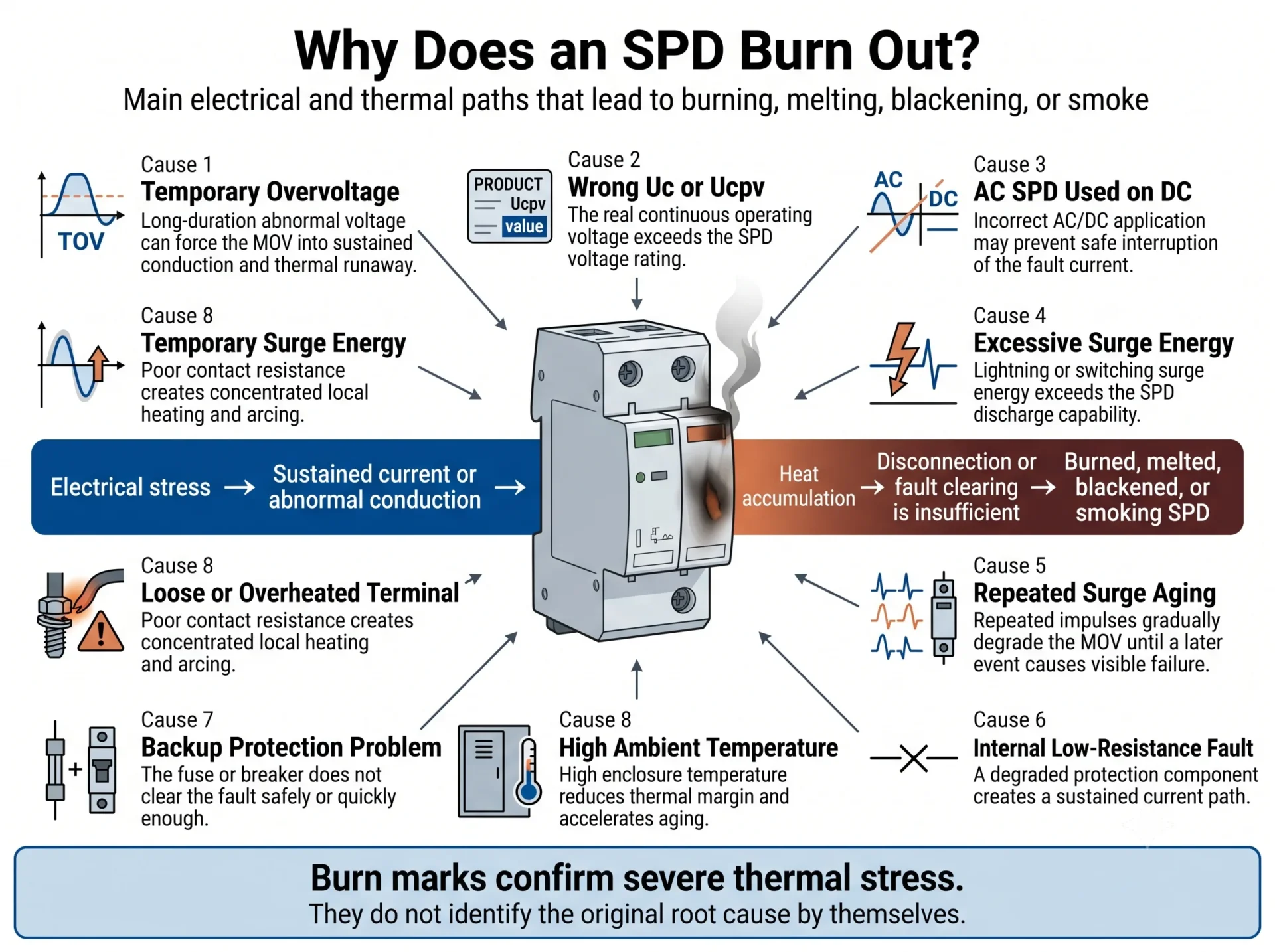
Common triggers include temporary overvoltage, an unsuitable Uc or Ucpv, AC/DC misuse, excessive surge energy, repeated MOV degradation, loose terminals, local arcing and unsuitable backup protection.
The visible burning is often the final stage of a sequence. One event may start the failure, while another condition allows the temperature and damage to continue increasing.
What Should You Do Immediately After Finding a Burned SPD?
A blackened, melted, smoking or cracked SPD must not remain energized. Isolation and inspection should be performed only by qualified personnel following the site’s electrical safety and lockout procedures.
- Make the circuit safe. Isolate the affected circuit before touching the SPD, cartridge, terminals or conductors.
- Do not immediately install another cartridge. A new module can fail again if abnormal voltage, incorrect wiring or fault-current conditions remain.
- Photograph the installation before removal. Capture the front, sides, base, terminals, conductors, upstream device and complete label.
- Preserve the failed device. Do not discard or clean the damaged cartridge and base before the investigation.
- Inspect the complete protection branch. The original cause may be outside the visible SPD enclosure.
A red status indicator is not the same as external burning. A red window often indicates that a protection path has disconnected or reached end of life. Charring, melting or smoke indicates a more severe event requiring root-cause investigation.
The Five Main Mechanisms Behind SPD Burnout
Instead of treating every possible trigger as a separate cause, it is more useful to understand the physical mechanism that produced the heat and damage.
| Burnout mechanism | What usually happens | Typical evidence |
|---|---|---|
| Thermal runaway | The MOV develops increased leakage or sustained conduction, so temperature and current continue rising. | Internal cartridge charring, discoloration, deformation or thermal-disconnector damage. |
| Local connection heating | A loose, contaminated or unsuitable connection creates high resistance and concentrated heat. | Burning centred on one terminal, conductor, ferrule or plug-in contact. |
| Sustained fault current | A degraded protection component or fault path remains connected long enough for power-frequency or DC current to enlarge the damage. | Cartridge and base both melted, heavy contact damage or extensive carbonization. |
| DC arcing | A conductive or arc path in a DC circuit is not interrupted safely and continues heating nearby insulation. | Long carbon tracks, severe pole-to-pole or pole-to-earth damage, especially in PV systems. |
| Excess impulse energy | One severe event or multiple impulses exceed the SPD’s current and energy capability. | Sudden rupture, multi-pole damage or failure after a recorded lightning or switching event. |
Thermal Runaway from TOV, Wrong Uc or Progressive MOV Degradation
A transient surge normally lasts for a very short time. A temporary overvoltage can remain for much longer. If the voltage across an MOV remains above a safe continuous level, the MOV may develop increased leakage, enter sustained conduction or fail into a low-resistance condition.
As temperature rises, the MOV’s electrical behaviour can change further. This may allow still more current to flow, producing thermal runaway.
Common triggers include:
- Neutral loss or high neutral impedance
- Phase-to-neutral voltage displacement
- Incorrect earthing or protection mode
- Uc selected too low for actual AC operating conditions
- Ucpv selected too low for maximum PV string voltage
- Repeated surge exposure and progressive MOV aging
- Generator, transformer, utility or inverter abnormalities
A high Imax value does not automatically solve a sustained overvoltage problem. Imax describes a specified impulse-current capability; it does not replace correct Uc, Ucpv and TOV selection.
Local Connection Heating at the Terminal or Plug-In Contact
A high-resistance connection can generate concentrated heat during normal current flow or surge discharge. The strongest damage may remain near the screw terminal, cable entry or cartridge-to-base contact.
Possible causes include:
- Insufficient or excessive terminal torque
- Incorrect conductor cross-section
- Damaged, loose or incompletely inserted conductor
- Unsuitable ferrule or cable lug
- Stray wire strands or poor crimping
- Dust, moisture, corrosion or conductive contamination
- Loose or overheated plug-in contacts
A burned terminal does not prove that the MOV failed first. The terminal or plug-in contact may have started the thermal event.
Sustained Fault Current After the SPD Becomes Conductive or Short-Circuit
MOV-based SPDs commonly include an internal thermal disconnector. However, the thermal disconnector and upstream overcurrent protection perform different functions.
If a severe internal fault creates a low-resistance path, the remaining damage depends partly on the available fault current and whether the protective arrangement isolates it safely.
Damage may become more severe when:
- Required backup protection is absent
- The upstream protective rating exceeds the manufacturer’s permitted value
- The fuse or breaker has insufficient breaking capacity
- Prospective short-circuit current was not considered
- The SPD and upstream protection were not coordinated
- The internal thermal-disconnection system does not isolate the event as intended
There is no single universal fuse, breaker or special protector suitable for every SPD. The correct protective arrangement depends on the exact SPD, manufacturer instructions, circuit and available fault current.
Sustained DC Arcing or Incorrect AC/DC Application
An AC SPD should not be installed on a PV string, battery system or other DC circuit unless the exact model is explicitly rated for that DC application and circuit configuration.
AC and DC ratings cannot be compared only by looking at a similar voltage number. Internal circuit design, disconnection behaviour, pole arrangement and fault interruption requirements may differ.
DC current does not pass through natural current zero points in the same way as AC current. Once an arc or conductive path develops, interruption can therefore be more difficult.
Never replace a failed PV DC SPD with an AC SPD merely because both labels show 600 V, 1000 V or another apparently similar voltage. Suitability must be confirmed from the exact manufacturer rating and circuit configuration.
Surge Energy Exceeded the SPD’s Intended Capability
An SPD has finite current and energy capability. One severe event, repeated impulses or improper coordination between Type 1 and Type 2 protection can expose the device to more energy than it was designed to handle.
| Parameter | What it describes | Why it matters here |
|---|---|---|
| In | Nominal discharge current under specified test conditions. | Helps describe repeated Type 2 impulse capability. |
| Imax | Maximum Type 2 discharge current under specified conditions. | A larger Imax does not correct TOV, wiring or AC/DC application errors. |
| Iimp | Lightning impulse current capability, normally associated with Type 1 duty. | Important where partial lightning current may enter the installation. |
| Up | Voltage protection level during specified discharge conditions. | Must remain coordinated with the impulse withstand level of protected equipment. |
High ambient temperature can reduce thermal margin and accelerate all five mechanisms, but it is normally an aggravating condition rather than a complete root-cause explanation by itself.
Why Did the SPD Burn but the Circuit Breaker Did Not Trip?
Severe local heat does not always create a current profile that causes the upstream breaker to trip quickly.
The breaker may remain closed because:
- The event was a very short impulse rather than a sustained overcurrent
- A high-resistance fault produced local heat without very high total current
- The current stayed below the breaker’s instantaneous trip threshold
- The fault path did not pass through the expected protective device
- The breaker was not coordinated with the SPD
- The upstream rating exceeded the SPD manufacturer’s permitted backup value
- Internal arcing or disconnection created a complex intermittent current path
An unsuitable protective device may nuisance-trip during normal surge discharge or fail to meet the installation requirements. Check the SPD manufacturer’s coordination instructions, protective-device characteristics and prospective short-circuit current.
Does a Burned SPD Mean the Product Was Poor Quality?
Not necessarily. A product defect is a valid possible cause, but the same external appearance can be produced by abnormal voltage, incorrect application, poor connections, unsuitable protection or excessive energy.
The following findings help determine which investigation direction is stronger.
| Finding | More consistent with system or application issue | More consistent with possible product issue |
|---|---|---|
| Different SPD brands repeatedly fail at the same installation position | Strong indication | Weaker indication |
| The measured operating voltage exceeds Uc or Ucpv | Strong indication | Does not prove a product defect |
| An AC SPD was installed on an unapproved DC circuit | Very strong indication | Weak indication |
| Burning is concentrated at a loose or incorrectly prepared terminal | Strong indication | Weaker unless the terminal design is defective |
| The same batch shows similar internal damage across unrelated correctly designed projects | Weaker indication | Strong indication requiring batch investigation |
| Ratings, wiring, voltage and protection are verified, but identical devices fail repeatedly | Weaker indication | Stronger indication |
| Internal soldering, contact, thermal disconnector or component assembly is abnormal | Weak indication | Strong indication |
| The label, certificate scope or internal construction does not match the claimed rating | Weak indication | Very strong indication |
The matrix helps determine what should be checked next. Final responsibility may require site measurements, batch records, retained samples, internal examination and independent laboratory analysis.
What Should a Credible Supplier Investigation Include?
- Complete model and batch-number verification
- Comparison with production and inspection records
- Review of retained samples from the same batch, where available
- Internal examination of the cartridge, contacts and disconnection mechanism
- Comparison between field voltage conditions and product ratings
- Review of upstream protection and wiring
- Clear conclusion separating confirmed facts from possible causes
What Can the SPD Burn Pattern Tell You?
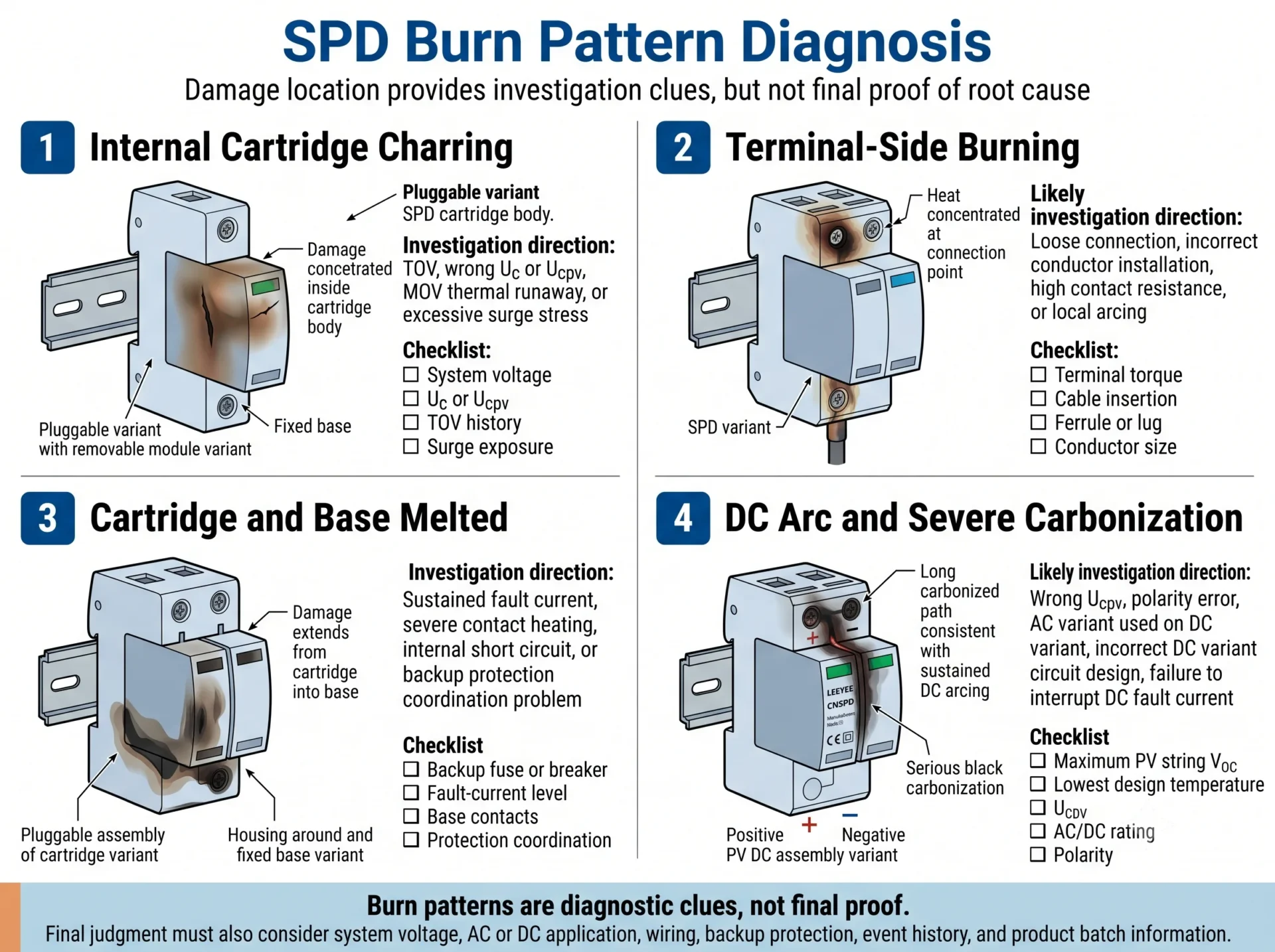
The location and shape of visible damage can help determine what to inspect first. Burn patterns are investigation clues, not final proof.
| Visible pattern | First investigation direction | Evidence to collect |
|---|---|---|
| Charring concentrated inside the cartridge | Check thermal runaway, TOV, Uc or Ucpv, repeated degradation and surge stress. | Complete label, measured voltage, event history and internal inspection. |
| Burning concentrated at a screw terminal | Check insertion, torque, conductor size, ferrule, contamination and local arcing. | Close terminal photos, conductor sample and torque records. |
| Cartridge burned but base appears intact | Investigate module-level failure, but do not assume the base contacts remain safe. | Base model, contact condition, discoloration and electrical inspection. |
| Cartridge and base both melted | Check sustained fault current, contact heating and protection coordination. | Upstream device, short-circuit data and complete branch wiring. |
| Several poles damaged together | Check system overvoltage, common-mode surge, neutral event or high-energy incident. | Voltage records, grounding arrangement and other damaged equipment. |
| One pole repeatedly burns | Check voltage across that path, pole-to-earth conditions and repeated local heating. | Per-pole measurements and wiring diagram. |
| PV DC SPD shows long carbon tracks | Check DC rating, Ucpv, polarity, circuit topology and AC/DC mismatch. | String Voc, lowest design temperature and full model label. |
A severely burned base, terminal block or enclosure should not be reused merely because it still appears mechanically complete.
How Does Burnout Diagnosis Differ Between AC and PV DC SPDs?
AC distribution board
- Nominal and measured L-N and L-L voltage
- Neutral continuity and neutral-loss history
- TN, TT or IT earthing arrangement
- Uc for each protection path
- 3+1 versus 4+0 arrangement
- Upstream protection coordination
- Prospective short-circuit current
PV DC combiner box or inverter input
- Maximum string open-circuit voltage
- Voc correction at minimum temperature
- Number of modules in series
- Ucpv and exact DC rating
- Positive and negative voltage to earth
- Polarity and circuit configuration
- DC fault-current and isolation behaviour
A PV SPD must be selected from the actual array design. The marketed DC class of an inverter does not by itself confirm the maximum voltage that each SPD path will experience.
What Evidence Is Needed to Determine Why an SPD Burned?
One close-up photograph of the darkest area is not enough for a credible diagnosis.
| Information | Why it matters | What to provide |
|---|---|---|
| Complete SPD label | Confirms model, AC/DC rating, Uc or Ucpv, type and current ratings. | Clear front and side photographs. |
| Damage location | Separates cartridge, terminal, base-contact and conductor damage. | Front, rear, side, terminal and base photographs. |
| System voltage | Shows whether the SPD experienced unsuitable continuous voltage. | Nominal voltage and actual measured values. |
| AC or DC application | Confirms whether the product rating matches the circuit. | Single-line diagram and equipment information. |
| Earthing arrangement | Changes voltage exposure and protection mode. | TN-S, TN-C-S, TT or IT description and diagram. |
| Backup protection | Allows fault-current coordination to be reviewed. | Fuse or breaker model, rating and breaking capacity. |
| Conductors and terminals | Helps identify connection heating and arcing. | Cable size, ferrule or lug type, length and torque record. |
| Event history | Helps distinguish lightning, switching, TOV, neutral loss and gradual aging. | Date, weather, alarms, outages and nearby damage. |
| Batch and installation history | Helps identify repeated site conditions or possible batch patterns. | Installation date, quantity affected, batch number and previous cases. |
Need Help Reviewing a Burned SPD?
Send clear photos of the label, damage area, base, terminals and upstream device, together with system voltage, AC or DC application, wiring diagram and protection information.
Step-by-Step SPD Burnout Diagnostic Workflow
- Confirm the circuit is safe. Do not inspect or remove the SPD while energized.
- Record the original installation. Take wide and close photographs before moving conductors.
- Identify the damage centre. Determine whether the event began in the cartridge, base, terminal or conductor.
- Verify the full model. The cartridge and base may have separate model codes.
- Confirm AC or DC suitability. Check the exact rated application.
- Compare Uc or Ucpv with actual voltage. Include abnormal and maximum operating conditions.
- Inspect wiring and earthing. Confirm every protection path is connected correctly.
- Inspect terminals and contacts. Look for torque, ferrule, corrosion, discoloration and carbonization issues.
- Review backup protection. Compare the actual device with the manufacturer’s requirements.
- Check event history. Review lightning, TOV, neutral loss, switching and inverter alarms.
- Compare other failures. Determine whether the pattern is site-specific, model-specific or batch-related.
- Correct the cause before replacement. The new SPD is not the corrective action by itself.
Can You Replace Only the Plug-In SPD Cartridge?
Sometimes—but only after the base, contacts, terminals and complete protection branch have been inspected.
Cartridge-only replacement may be possible when:
- The base has no cracking, melting or carbonization
- Plug-in contacts show no overheating or loss of pressure
- Terminals and conductors remain undamaged
- The root cause has been identified and corrected
- The new cartridge is approved for the exact base
- The manufacturer permits cartridge replacement
Replace the complete SPD when:
- The base is melted, cracked, distorted or carbonized
- Contacts are burned, loose or discoloured
- Terminal insulation has been damaged
- Compatibility cannot be verified
- The original configuration or rating was incorrect
- The cause remains unresolved after severe burning
How to Select the Correct Replacement SPD
| Parameter | What to verify | Common mistake |
|---|---|---|
| AC or DC rating | Confirm the exact circuit and approved application. | Using an AC model on a PV DC circuit. |
| Uc or Ucpv | Calculate from real continuous and maximum operating voltage. | Choosing from nominal system voltage alone. |
| SPD type | Confirm Type 1, Type 2 or Type 1+2 according to installation position. | Using Type 2 where partial lightning current may enter. |
| In, Imax or Iimp | Match current capability to the protection concept. | Assuming the largest Imax fixes every failure. |
| Up | Coordinate with protected equipment impulse withstand. | Increasing Uc without checking protection level. |
| Protection mode | Confirm L-N, L-PE, N-PE or PV pole-to-earth arrangement. | Changing 3+1 and 4+0 without checking earthing. |
| Fault-current conditions | Check prospective short-circuit current and manufacturer instructions. | Ignoring available fault current. |
| Backup protection | Coordinate fuse or breaker type, rating and breaking capacity. | Using one universal protective device for every SPD. |
| Base compatibility | Verify the exact cartridge and base combination. | Assuming similar size means compatibility. |
| Certification | Confirm required IEC, EN, UL or project-document scope. | Checking only the label instead of the certificate scope. |
Treat a burned SPD as a diagnosis event, not only a spare-parts order. The replacement must address both the damaged device and the electrical condition that caused or enlarged the damage.
Frequently Asked Questions About Burned SPDs
Does a burned SPD always mean poor product quality?
No. A product defect is one possible cause, but TOV, wrong Uc or Ucpv, AC/DC misuse, excessive surge energy, loose connections, wiring errors and unsuitable fault-current protection can create similar damage. The conclusion should follow the complete evidence.
Can lightning make an SPD burn or melt?
Yes. A severe or repeated lightning-related event can exceed the SPD’s current and energy capability. The visible burning may then be enlarged by continued power-frequency or DC fault current.
Can an SPD burn without a lightning strike?
Yes. Neutral loss, temporary overvoltage, utility abnormalities, switching events, wrong voltage selection, terminal heating, AC/DC misuse and internal defects can all cause severe damage without lightning.
Why did the SPD burn but the breaker did not trip?
Severe local heat can develop without producing a current that reaches the breaker’s instantaneous trip threshold. A short impulse, high-resistance fault, intermittent arc or unsuitable protective-device coordination may produce different breaker responses.
Can an AC SPD burn when used in a DC solar system?
Yes. An AC SPD may have unsuitable voltage, circuit and disconnection characteristics for DC operation. Use only a model explicitly rated for the exact PV DC voltage and circuit configuration.
Can a loose terminal make an SPD turn black?
Yes. A loose or high-resistance connection can produce concentrated heating and arcing. If the strongest damage is near the terminal, inspect torque, cable preparation, ferrules, conductor size, corrosion and plug-in contacts.
Should I select a higher Uc after an SPD burns?
Not automatically. First confirm the real continuous voltage, earthing arrangement, protection mode and TOV risk. A higher Uc may improve voltage margin but may also affect the voltage protection level.
Will a higher Imax prevent an SPD from burning?
Not in every case. Higher Imax does not correct TOV, wrong Uc, AC/DC misuse, loose terminals, wiring errors or unsuitable backup protection.
Can I replace only the plug-in module?
Only when the base, contacts, terminals and conductors remain undamaged, the failure cause has been corrected and the replacement cartridge is approved for the exact base.
What should I send to the SPD supplier for diagnosis?
Send photographs of the complete label, damage area, base, terminals, wiring and upstream protective device. Also provide system voltage, AC or DC application, earthing arrangement, wiring diagram, conductor size, installation date, batch number and event details.
Technical Review and Reference Basis
This guide is reviewed as a practical B2B diagnostic resource. Final failure attribution may require field measurements, destructive examination or independent laboratory analysis.
Technical references
- IEC 61643-11 — Low-voltage surge protective devices for AC power systems: requirements and test methods.
- IEC 61643-31 — Surge protective devices for photovoltaic installations: requirements and test methods.
- Manufacturer instructions for Uc, Ucpv, TOV behaviour, backup protection and maximum permissible upstream protection.
- Project-specific electrical installation, lightning-protection and fault-current requirements.
Need a Replacement SPD Recommendation?
Send your damaged SPD photos, complete model label, system voltage, wiring diagram and backup protection information. LEEYEE can help you identify the likely investigation direction and confirm suitable AC or PV DC replacement parameters.
Technical note: This page supports initial investigation and replacement selection. It does not replace site electrical testing, manufacturer-specific instructions or a formal laboratory failure report.
