
A UPS is not a substitute for a complete SPD strategy. The correct protection levels depend on the actual single-line diagram, earthing system, lightning exposure, prospective short-circuit current, UPS topology, cable distance, A/B redundancy and equipment withstand requirements.
Table of Contents
Why Data Center Surge Protection Requires Multiple Coordinated Levels
Data centers contain several power conversion, transfer, distribution and communication layers. A transient can enter through an external service, be induced into a long conductor or originate from switching equipment inside the facility.
External surge exposure
Lightning effects and utility switching disturbances can place transient stress on incoming switchgear, ATS equipment, UPS inputs and connected control circuits.
Internal switching events
Generators, ATS operation, chillers, motors, VFDs, contactors and UPS bypass events can create or redistribute transient overvoltages inside the installation.
Parallel copper entry paths
Ethernet, PoE, BMS, DCIM and sensor wiring may carry a surge into equipment even when the AC distribution system already includes SPDs.
A UPS supports power continuity and specified power-quality conditions. An SPD limits short-duration transient overvoltages and diverts surge current. Internal UPS protection varies by model and topology, so the main input, bypass and downstream distribution must still be reviewed.
IEC 61643-11 defines requirements and test methods for SPDs connected to AC low-voltage power systems. IEC 61643-12 addresses selection, operation, location and coordination. A reliable design therefore requires both a suitable SPD and a coordinated installation. [1] [2]
Data Center Surge Protection Architecture
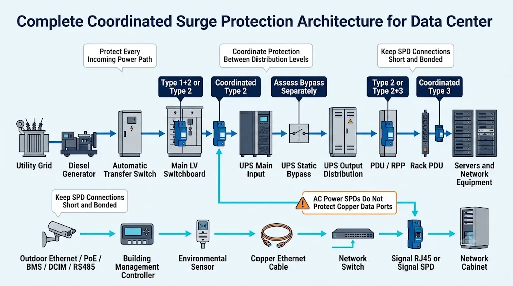
Start with every power and copper communication path. Do not begin by selecting an SPD model and then looking for somewhere to install it.
Control incoming energy
Assess the utility service, generator source, ATS and main low-voltage switchboard for the surge duty that can reach the facility.
Coordinate downstream protection
Review the UPS input, bypass, output distribution, PDU and RPP according to distance, topology and the remaining voltage stress.
Protect copper interfaces
RJ45, PoE, RS485, Modbus and sensor lines require interface-specific protection. An AC power SPD cannot directly protect these ports.
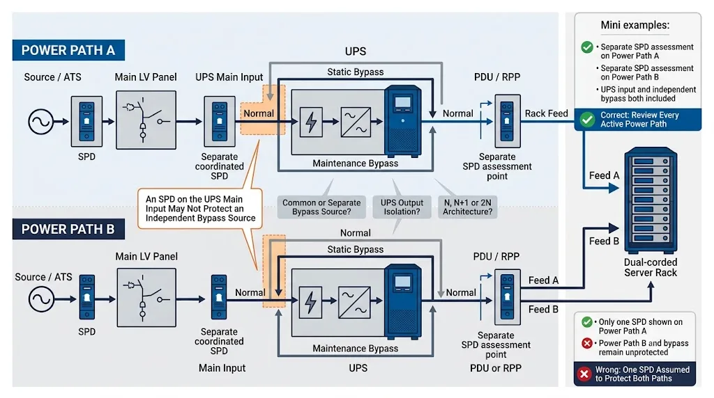
An SPD on Power Path A does not automatically protect Power Path B. Confirm the source, UPS, bypass, downstream distribution and rack feed on each side under normal, fault and maintenance operating conditions.
Where Are SPDs Installed in a Data Center?
The table provides a practical starting point. It does not treat one fixed discharge-current rating as correct for every data center.
| Installation point | Protection objective | Common starting point | Confirm before ordering |
|---|---|---|---|
| Service entrance or main LV switchboard | Limit high-energy surges entering the low-voltage installation. | Type 1+2 where lightning-current duty applies. Type 2 may apply where Type 1 duty is not required. | External LPS, service exposure, risk assessment, earthing system, Uc, Iimp, Up, fault current and backup protection. |
| Generator or ATS sections | Protect source inputs, transfer equipment and sensitive controllers. | Coordinated power SPD according to the source path and protection-zone boundary. Separate signal protection where required. | Utility and generator routing, ATS arrangement, controller voltage, exposed conductors and upstream SPD position. |
| UPS main input | Protect input switchgear, rectifier and other upstream-facing UPS components. | Coordinated Type 2 in many internal locations. Type 1+2 may apply where lightning-current duty remains. | UPS voltage, topology, upstream distance, source exposure, Uc, Up, fault current and UPS manufacturer requirements. |
| Static or maintenance bypass | Prevent an unprotected bypass route from reaching downstream loads. | Assess as a separate path when it is supplied independently or bypasses the protected UPS input point. | Common or separate source, switch arrangement, maintenance state and upstream coordination. |
| UPS output distribution | Limit residual or newly introduced transient stress before downstream panels. | Additional Type 2 protection where topology, distance, exposure or equipment requirements justify another protection level. | Output isolation, neutral arrangement, conductor length, downstream immunity and integrated protection. |
| Floor PDU, row PDU or RPP | Provide local coordination for branch circuits and sensitive IT loads. | Type 2 or coordinated Type 2+3 according to the remaining surge requirement. | Voltage, phase arrangement, distance, Up, branch fault current, enclosure space and remote alarm. |
| Rack PDU or point of use | Reduce residual transient stress close to sensitive equipment. | Type 3 or equipment-level protection as the final part of a coordinated upstream system. | Integrated protection, replaceability, status indication, load rating and upstream coordination. |
| RJ45, PoE, BMS, DCIM and signal lines | Stop surges entering through copper communication and control interfaces. | Interface-specific SPD intended for telecommunications or signalling networks. | Working voltage, pin assignment, data rate, PoE standard, current, insertion loss, shielding and grounding. |
The SPD must match its installation point, voltage, earthing system, expected surge duty, voltage protection level, fault conditions, backup protection, enclosure and maintenance strategy.
Main LV Switchboard, Generator and ATS Protection
Main low-voltage switchboard
The main switchboard is normally the first location evaluated for high-energy surge protection. The words “data center” alone do not determine whether the SPD must be Type 1, Type 2 or combined Type 1+2.
Confirm:
- Whether the building has an external lightning protection system.
- Whether an exposed service can conduct lightning current into the structure.
- The applicable electrical and lightning risk assessment.
- Whether the system is TN-S, TN-C-S, TT or IT.
- Phase-to-neutral and phase-to-phase operating voltage.
- Prospective short-circuit current at the SPD location.
- Required fuse or circuit-breaker coordination.
See the SPD Uc Selection Guide for voltage-selection logic.
Generator and ATS paths
An ATS can connect utility power, generator power and downstream distribution through different conductors and switch positions. Trace each source rather than assuming one SPD covers every operating condition.
- Review the utility-side path.
- Review the generator-side path.
- Review the ATS output and downstream panel.
- Review ATS controller, monitoring and communication circuits.
This does not mean every ATS needs an SPD at every terminal. It means every active power and control path must be included in the engineering assessment.
The correct 3+1, 4+0, 3P+N or other arrangement depends on the earthing system and project design. Review the TN-S SPD Wiring Guide before confirming the pole arrangement.
Data Center SPD Protection for UPS Input, Bypass and Output
“Install one SPD before and one SPD after every UPS” is not a complete design rule. The answer depends on how the UPS is supplied, how its bypass is arranged, whether the output is isolated and how the downstream system is distributed.
UPS main input
The input SPD helps protect the UPS input switchgear, rectifier and related components. It must be coordinated with the main switchboard SPD and selected for the actual UPS input system.
Static bypass
If the bypass has a separate source or avoids the protected main-input point, it requires its own assessment. Otherwise, a transient may reach the load through the bypass route.
Maintenance bypass
Review the electrical condition when the UPS is isolated. Maintenance operation must not unintentionally remove the only effective protection level from the critical path.
What We Check on a Data Center Single-Line Diagram
A single-line diagram provides more useful information than an enquiry that only states “400 V, Type 2, 40 kA.” These are the first conditions that should be checked before recommending a data center SPD.
- Whether the UPS main input and bypass use a common or separate source.
- Whether Power Path A and Power Path B remain independent in every operating mode.
- Distance between the main-switchboard SPD and UPS input.
- Whether the UPS output creates a new neutral or earthing arrangement.
- Whether a PDU contains an isolation transformer or integrated SPD.
- Prospective short-circuit current and upstream protective device at each proposed SPD location.
- How remote alarm contacts will connect to BMS or DCIM.
- Whether a module can be isolated and replaced without disabling both redundant power paths.
- Whether exposed PoE, Ethernet, RS485 or sensor lines bypass the AC protection system.
- Whether the specified Uc, Up, Iimp, In and Imax refer to the correct test class and protection mode.
Mark every proposed SPD location and add the system voltage, earthing arrangement, upstream protective device, fault current, UPS path, downstream distance and connected equipment.
Example: 400/230 V TN-S Data Center with Dual UPS Paths
This example shows the decision process. It is not a universal specification and does not replace the project designer’s final calculation.
Example project conditions
Medium-sized data center with redundant UPS paths, floor PDUs, BMS communication and outdoor security equipment.
Assess Type 1 duty at the main switchboard
Because the building has an external lightning protection system, the incoming arrangement must be assessed for lightning-current duty. A combined Type 1+2 solution may be appropriate, but the required Iimp, topology and backup protection still depend on the risk assessment and current-sharing conditions.
Coordinate UPS A and UPS B independently
Each UPS path has its own input and downstream distribution. The SPD positions and upstream protective devices should therefore be documented separately for Path A and Path B.
Review both independent bypass feeds
The bypass conductors do not automatically pass through the same protected point as the UPS main inputs. Each bypass source must be traced to determine whether additional coordinated protection is required.
Reassess protection at the 60 m PDU location
The long downstream route can create additional exposure and separation from the upstream SPD. The PDU should be assessed for a local coordinated Type 2 stage, with Up selected for the downstream equipment.
Protect RS485 and PoE as separate interfaces
The AC SPD cannot protect BMS or camera data ports. RS485 protection must match the signal voltage and topology. PoE protection must match the data rate, pair use, PoE power class and grounding arrangement.
Confirm the final product parameters
The project engineer and supplier must still confirm Uc, Up, Iimp, In, Imax, protection modes, short-circuit conditions, backup protection, remote alarm and replacement-module requirements for each location.
PDU, RPP and Rack-Level Surge Protection
Data centers may use floor PDUs, busway tap-off units, row-level PDUs, remote power panels, rack PDUs or a combination of these. The phrase “PDU with surge protection” does not prove that the installed protection is coordinated with the rest of the facility.
Floor PDU or RPP
- Confirm voltage and earthing system.
- Check distance from the upstream SPD.
- Determine the remaining protection requirement.
- Confirm branch fault current and backup protection.
- Use suitable remote contacts for BMS or DCIM monitoring.
- Provide safe access for inspection and replacement.
Rack PDU
- Determine whether an SPD is actually integrated.
- Check whether the protection module is replaceable.
- Confirm voltage, phase, load current and connection system.
- Do not replace upstream protection with a rack-level device.
- Check local and remote failure indication.
- Plan maintenance without disabling both rack feeds.
Point-of-use protection is intended to manage lower residual energy after upstream SPDs have already limited the main surge threat.
RJ45, PoE, BMS and Signal Surge Protection for Network Cabinets
An SPD in the low-voltage panel cannot directly protect a transient entering through an RJ45, PoE or control terminal. Every exposed copper interface must be assessed separately.
Ethernet
Match the SPD to transmission speed, cable category, shielding, pin assignment and grounding.
Power over Ethernet
Confirm the PoE standard, pair use, maximum power, data rate and grounding arrangement.
BMS and DCIM
Review RS485, Modbus, dry contacts, 24 V controls and analog signal circuits separately.
Outdoor systems
Assess rooftop devices, security cameras, access control, weather equipment and inter-building copper links.
IEC 61643-21:2025 applies to SPDs connected to telecommunications and signalling networks and includes networks that provide power over the same conductors, such as PoE. IEC 61643-22 covers their selection, location and coordination. [4] [5]
| Interface | Do not select from this alone | Confirm these parameters | Related technical guide |
|---|---|---|---|
| RJ45 Ethernet | “RJ45 connector” | 100 Mbps, Gigabit or higher speed, cable category, shielding, pin use and grounding. | RJ45 SPD Selection |
| PoE | “Supports PoE” | IEEE PoE standard, power class, pairs, voltage, current, data rate and shield. | PoE Surge Protection |
| RS485 / Modbus RTU | “Two-wire signal” | Working voltage, reference conductor, topology, baud rate and grounding. | RS485 SPD Guide / Modbus Protection |
| 24 V control | “24 V signal” | AC or DC, DI, DO, AI or AO, loop current, conductor count and reference. | 24 V Signal SPD |
| 4–20 mA | “Analog signal” | Two-wire or four-wire loop, voltage budget, resistance and grounding. | 4–20 mA SPD Guide |
Powered media converters, metallic cable elements, equipment power supplies, cabinets and parallel copper control wiring may still require bonding or surge protection.
Include Cooling, Fire, Security and Monitoring Systems
A data hall can remain electrically energized and still lose availability if cooling, fire protection, environmental monitoring or access-control systems fail.
CRAC, CRAH and chillers
Review main power, VFD inputs, control supplies, outdoor sensors and communication interfaces as separate circuits.
Fire and security systems
Assess CCTV, access control and alarm interfaces without interfering with the applicable system approval or certification.
BMS and environmental sensors
Confirm signal type, working voltage, current, bandwidth, shielding and grounding before selecting the signal SPD.
Earthing, Bonding and Cable Length Determine Real Protection
A correctly rated SPD can still provide poor protection when its connecting conductors are long, looped or poorly bonded.
Keep SPD connections short
The equipment experiences the SPD voltage protection level plus additional voltage generated across the connecting conductors while surge current flows.
Place the SPD close to the conductors and PE or earth connection it protects. Avoid unnecessary loops and remote mounting.
See the SPD 0.5 m Connection-Length Guide .
Use coordinated equipotential bonding
Switchboards, UPS systems, PDUs, cabinets, cable shields and communication SPDs should reference the project’s bonding system.
An isolated earth electrode for one device can create a dangerous potential difference instead of improving protection.
See the SPD Grounding and Bonding Guide .
IEC 62305-4:2024 covers the design, installation, inspection, maintenance and testing of surge protection measures for electrical and electronic systems inside structures. [3]
SPD Design Must Support the Data Center Redundancy Strategy
Uptime Institute describes Tier III infrastructure as concurrently maintainable and Tier IV infrastructure as fault tolerant. These are performance objectives, not a list of mandatory SPD part numbers. [7]
The practical SPD question is not “Which model is Tier IV certified?” It is whether the protection arrangement can be monitored, isolated and maintained without defeating the required availability of the power path.
Independent A/B review
Document the SPD position, upstream protective device and replacement method for each power path.
Remote status monitoring
Suitable dry contacts can report an end-of-life condition to BMS or DCIM without waiting for a manual inspection.
Replaceable protection modules
Pluggable modules can simplify maintenance when the project also defines safe isolation, compatible cartridges and spare stock.
It does not prove that the remaining protection level is adequate, that replacement can be completed live or that the opposite power path is unaffected.
How Often Should Data Center SPDs Be Checked?
There is no single inspection interval suitable for every facility. The schedule should reflect manufacturer instructions, local requirements, lightning exposure, monitoring capability, maintenance policy and the consequence of losing protection.
- Continuously monitor remote status contacts where available.
- Include SPD condition in normal switchboard and PDU inspections.
- Inspect after a known lightning or major electrical event.
- Check the visual status indicator on every module.
- Verify the backup fuse or breaker condition.
- Inspect terminals for looseness, heating or contamination.
- Confirm that PE and bonding conductors remain secure.
- Record the installation point, module code and replacement date.
- Keep compatible spare modules for critical locations.
- Investigate repeated failures instead of only changing cartridges.
Check incorrect Uc selection, temporary overvoltage, neutral faults, wrong topology, poor backup coordination, excessive thermal stress or an unsuitable installation position.
IEC vs UL Data Center SPD Specifications
Do not copy an IEC specification directly into a North American project, or copy UL terminology into an IEC-based switchboard order. Confirm the applicable market and equipment approval route.
| Project type | Primary product basis | Common specification language | Important procurement check |
|---|---|---|---|
| IEC-based project | IEC 61643-11 together with IEC 61643-01, with application principles from IEC 61643-12. | Type 1, Type 2, Type 3, Uc, Up, Iimp, In and Imax. | Confirm the exact product standard, test class, protection mode, earthing system and backup protection. |
| North American project | UL 1449 and the applicable electrical code and equipment requirements. | SPD Type, MCOV, VPR, nominal discharge current and SCCR. | Verify the exact UL certification category and whether the device is suitable for the proposed installation. |
| OEM panel or PDU integration | Product approval plus the requirements applying to the complete switchboard, panel or PDU. | Factory-installed device, component conditions, enclosure, disconnect and wiring requirements. | Do not assume an SPD certificate automatically approves the complete assembled equipment. |
They belong to different standards and classification systems. Always specify the required standard, test parameters and market approval instead of using the word “Type” by itself.
Information to Send the Data Center SPD Manufacturer
A supplier cannot make a reliable recommendation from “400 V, 40 kA” alone. Include the following project information with the RFQ.
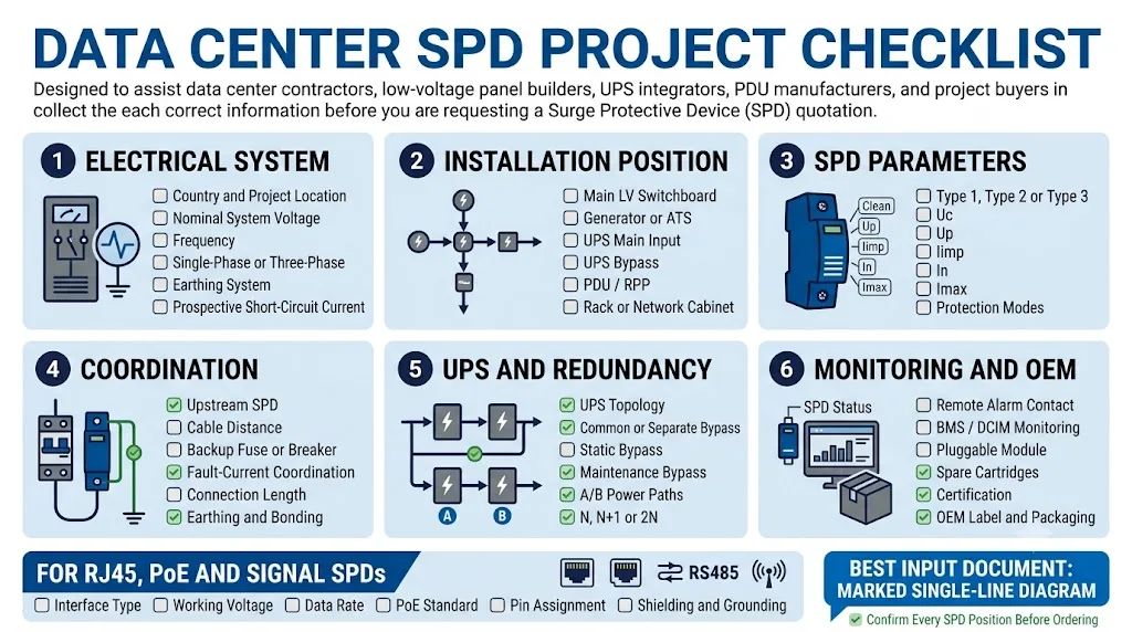
1. Electrical system
- Country and project location
- Nominal system voltage
- Frequency
- Single-phase or three-phase
- TN-S, TN-C-S, TT or IT system
- Phase and neutral arrangement
- Prospective short-circuit current
2. Installation position
- Service entrance or main LV board
- Generator or ATS section
- UPS main input
- Static or maintenance bypass
- UPS output panel
- PDU, RPP or rack PDU
- Network or control cabinet
3. SPD parameters
- Applicable standard
- Required SPD Type or test class
- Uc or MCOV
- Up or VPR
- Iimp, In and Imax where applicable
- Required protection modes
- Backup protective device
4. UPS and redundancy
- Single, parallel or modular UPS
- Common or separate bypass source
- Isolation-transformer arrangement
- N, N+1, 2N or other architecture
- A/B power-path diagram
- Concurrent-maintenance requirement
- Acceptable isolation procedure
5. Monitoring and mechanics
- Visual status indication
- NO/NC or changeover remote contact
- BMS or DCIM monitoring requirement
- Pluggable or fixed construction
- DIN-rail or panel mounting
- Available enclosure space
- Required spare-module quantity
6. Network and signal
- RJ45, PoE, RS485 or other interface
- Working voltage and current
- Data rate and transmission category
- PoE standard and power class
- Number and use of conductors
- Shielding and grounding method
- Connector and mounting style
What Weak Data Center SPD Specifications Get Wrong
Weak specification
- “Provide a 100 kA SPD for the data center.”
- “The UPS already protects everything.”
- “Install one SPD at the main panel.”
- “Use the same design for Power Path A and B without checking them.”
- “Any RJ45 SPD supports every Ethernet and PoE system.”
- “Remote alarm means the module can be replaced live.”
Project-ready specification
- Marks every installation point on the single-line diagram.
- States system voltage and earthing arrangement.
- Specifies the applicable standard and SPD classification.
- Includes fault current and backup-device coordination.
- Separates AC power, network and signal protection.
- Defines monitoring, isolation and replacement requirements.
Evidence to Check Before Approving a Data Center SPD
Do not approve a product only from a catalogue current rating. Confirm the exact model, its documentation and its replacement strategy.
Certificates and scope
Check that the certificate or report covers the exact ordered model, voltage, topology and protection class—not only another product from the same family.
View LEEYEE certificatesTechnical documentation
Review the datasheet, wiring diagram, dimensions, backup protection, remote-contact rating and replacement cartridge code.
View technical downloadsExact product traceability
Confirm stable part numbers, production labels, inspection records and long-term availability of compatible replacement modules.
View SPD product range- Applicable IEC, EN, UL or local product compliance.
- Test documentation for the exact ordered model.
- Correct Uc and topology for the earthing system.
- Clear Up, Iimp, In and Imax definitions.
- Short-circuit and backup-protection information.
- Remote-contact rating and wiring diagram.
- Compatible replacement modules with stable codes.
- Routine production inspection and traceability.
- OEM label, packaging and technical-file control.
- Long-term spare-module availability.
Send Us Your Data Center Single-Line Diagram
LEEYEE can review the proposed SPD positions for the main LV switchboard, UPS input, bypass path, PDU, RPP and network cabinets. We can also confirm OEM labels, remote contacts, replacement modules and project documentation.
Data Center Surge Protection Questions
Does a data center need SPDs if it already has a double-conversion UPS?
The UPS does not automatically remove the need for external surge protection. The input components still face upstream transient stress, and the bypass and downstream paths may require separate protection.
Should SPDs be installed on both the UPS input and output?
The input requires assessment because it protects upstream-facing UPS components. Output protection is conditional. Consider output isolation, cable distance, downstream distribution, switching sources and existing PDU protection.
Does an independent UPS bypass require a separate SPD?
It may. A separate assessment is particularly important when the bypass has a different source or does not pass through the same protected upstream point as the UPS main input.
What SPD Type is used at the main data center switchboard?
Type 1 or combined Type 1+2 is used where lightning-current duty applies. Type 2 may be appropriate where that duty is not required. Confirm the lightning protection design, service exposure and risk assessment.
Does every data center PDU need its own SPD?
Not automatically. Review the upstream SPD, conductor distance, distribution layout, switching exposure, equipment withstand level and any protection already integrated into the PDU.
Can one SPD protect both A and B power feeds?
Only when both feeds genuinely share the same protected point and the arrangement remains valid under every normal, bypass and maintenance condition. Most redundant paths should be documented separately.
Do fiber-optic lines need an RJ45 surge protector?
A fully dielectric fiber path does not conduct surge current like copper Ethernet. Powered media converters, metallic cable elements, power supplies and parallel copper control wiring still require review.
How often should data center SPD modules be replaced?
There is no universal calendar replacement period. Monitor the SPD condition, follow manufacturer instructions, inspect after major electrical events and replace failed modules with the exact compatible cartridge.
What information should be included in a data center SPD RFQ?
Include the single-line diagram, installation point, voltage, frequency, earthing system, fault current, applicable standard, SPD Type, Uc or MCOV, Up or VPR, discharge ratings, backup protection, UPS topology, remote contact and enclosure space.
Sources and Standards
- IEC 61643-11:2025, Low-voltage surge protective devices – Surge protective devices connected to AC low-voltage power systems – Requirements and test methods. IEC Webstore
- IEC 61643-12:2020, Low-voltage surge protective devices – Selection and application principles for SPDs connected to low-voltage power systems. IEC Webstore
- IEC 62305-4:2024, Protection against lightning – Electrical and electronic systems within structures. IEC Webstore
- IEC 61643-21:2025, SPDs connected to telecommunications and signalling networks – Requirements and test methods. IEC Webstore
- IEC 61643-22:2015, Telecommunications and signalling network SPDs – Selection and application principles. IEC Webstore
- IEC 61643-01:2024, Low-voltage surge protective devices – General requirements and test methods. IEC Webstore
- Uptime Institute, Tier Classification and Tier Certification principles for concurrently maintainable and fault-tolerant data center infrastructure. Uptime Institute
- UL Solutions, Surge Protective Device Testing and Certification Services, including evaluation to UL 1449. UL Solutions
