
IEC 60364 Clause 534 explains how surge protective devices should be selected and installed in a low-voltage electrical installation. For a panel builder, compliance is not confirmed by writing “Type 2, 40 kA” in the bill of materials. The SPD location, conductor route, backup protection, RCD position and earthing arrangement all affect the final result.
This guide converts the standard into a practical review process for main distribution boards, sub-distribution boards, control panels and OEM projects. It explains what must be checked before the SPD model and panel layout are approved.
Table of Contents
Quick Answer
An IEC 60364-5-53 Clause 534 review should treat the SPD, its connecting conductors and its protective devices as one installation system.
- Position the main SPD at the correct distribution level and close to the incoming conductors and main earthing connection.
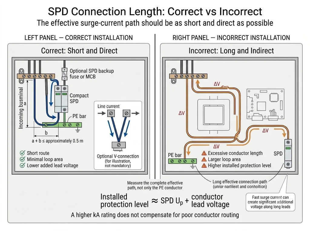
- Keep the effective surge-current path short, direct and free from unnecessary loops.
- For a conventional parallel branch connection, design around a combined effective connection path of approximately 0.5 m where practicable.[6][7]
- Check the SPD against the upstream fuse or circuit breaker and the prospective short-circuit current.
- Confirm whether the SPD is upstream or downstream of the RCD.
- Select the protection modes according to the actual TT, TN-S or TN-C-S arrangement.
- Approve Uc, Up, Iimp or In, short-circuit capability and backup-protection conditions—not only the maximum kA value.
What Does IEC 60364 Clause 534 Control?
IEC 60364-4-44 addresses protection against voltage disturbances and includes the requirements for transient-overvoltage protection. Clause 534 of IEC 60364-5-53 addresses how the SPD is selected, connected and coordinated within the installation.[1][3]
IEC 61643-11 and IEC 61643-01 are product standards. They address SPD safety, ratings and test methods. Clause 534 is an installation requirement. A tested SPD can still provide inadequate protection if it is installed with the wrong circuit or excessively long conductors.[4]
Is the SPD installed at the correct origin, distribution board or equipment level?
Do the SPD modes match the supply conductors and earthing system?
Can the SPD operate safely with the upstream OCPD and RCD?
Will conductor length increase the voltage reaching the protected equipment?
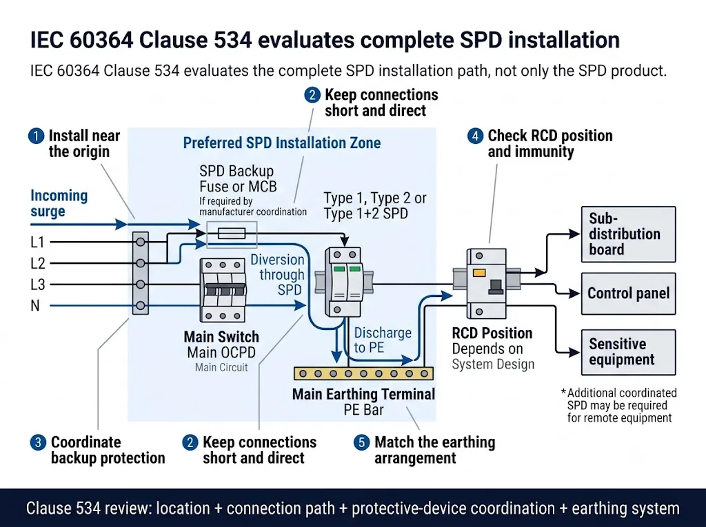
Buyer meaning: a product certificate and datasheet are necessary, but they do not prove that the completed panel has been installed correctly.
Clause 534 Practical Map for Panel Approval
This table is a practical navigation aid. It does not reproduce the full standard text.
| Clause area | What it addresses | Panel-builder check |
|---|---|---|
| 534.4.3 | SPD connection types | Confirm CT1, CT2 or the project-specified protection arrangement. |
| 534.4.4 | SPD selection | Check Uc, Up, discharge-current ratings, protection modes and temporary-overvoltage conditions. |
| 534.4.5 | Protection against overcurrent | Coordinate the SPD with its internal, dedicated or upstream protective device. |
| 534.4.6 | Fault protection | Ensure that the SPD arrangement does not compromise automatic disconnection or protective-conductor integrity. |
| 534.4.7 | SPDs and RCDs | Confirm SPD position, RCD impulse immunity and the applicable TT or TN design. |
| 534.4.8 | SPD connections | Review conductor route, connection arrangement and separation from protected wiring. |
| 534.4.9 | Effective protective distance | Assess remote equipment and whether another coordinated SPD is required. |
| 534.4.10 | Connecting conductors | Check conductor length, cross-section, terminal capacity and routing. |
Engineering conclusion: Clause 534 is not one wiring rule. It is a coordinated review of the SPD, its conductors and the surrounding protective system.
A Practical Clause 534 Review Workflow
-
Identify the installation point.
Confirm whether the SPD is at the origin, in a sub-distribution board or close to sensitive equipment. -
Confirm the earthing system.
Identify TT, TN-S, TN-C, TN-C-S or IT before selecting the protection modes. -
Determine the required SPD duty.
Confirm whether the project requires Type 1, Type 2, Type 1+2 or coordinated downstream protection. -
Approve the electrical ratings.
Check Uc, Up, Iimp, In, Imax, short-circuit capability and follow-current behaviour where applicable. -
Review the physical conductor path.
Measure the actual route from the live connection through the SPD to PE, PEN or the main earthing terminal. -
Coordinate the protective devices.
Check the upstream fuse or breaker, any dedicated SPD protection and the RCD position. -
Verify the finished panel.
Inspect terminal torque, conductor routing, indication, remote signalling and project documentation.
Where Should the SPD Be Installed?
Where surge protection is required at the origin, the main SPD should be placed close to the incoming supply conductors and the main earthing or equipotential bonding connection. The aim is to create a short path for surge current before it travels through the internal distribution system.[5][7]
The correct position is therefore not simply the nearest unused DIN-rail space. The SPD position should be planned together with the incoming terminals, main switch, protective device and PE or PEN bar.
At the main distribution board
Where the lightning protection design requires the panel to handle partial lightning current, a Type 1 or suitable combined Type 1+2 SPD is normally considered at the origin. This is common where an external lightning protection system is present, but the final requirement depends on the IEC 62305 design, separation conditions, national rules and project risk assessment.[7]
Where the design addresses induced lightning and switching transients without direct lightning-current duty, a Type 2 SPD is commonly considered. The project specification must confirm the required test class and discharge rating.
At a downstream board or remote load
An upstream SPD does not automatically provide the same protection at every remote panel or item of equipment. Cable length, induced voltage, reflected waves and locally generated switching disturbances can increase the voltage seen downstream.
A cable distance of approximately 10 m is commonly used as a trigger for reviewing whether an additional energy-coordinated SPD is needed closer to the equipment.[7][9] It is not a universal automatic pass-or-fail limit. Equipment impulse withstand, cable routing, shielding and the upstream SPD performance must also be checked.
Plan the SPD before the panel is full
Adding an SPD after the busbars, earth bars and outgoing devices have already been fixed often creates long conductors and poor separation between protected and unprotected wiring.
How Should the 0.5 m Connection Principle Be Applied?
The voltage protection level Up printed on the SPD is measured under defined test conditions. It is not automatically the voltage that the equipment sees after the SPD has been installed.
A fast surge current creates an additional voltage across the inductance of the connecting conductors. As the conductor route becomes longer, the installed protection level can become significantly higher.[6][7]
Conductor length, loop geometry and the rate of change of surge current all matter. A larger cable cross-section does not remove the inductive effect of an unnecessarily long route.
For a conventional parallel branch connection, the effective path from the live connection to the SPD and from the SPD to the PE or PEN connection should be kept as short and straight as possible. Manufacturer guidance based on IEC 60364-5-53 commonly uses a combined target of approximately 0.5 m.[6][7][10]
What should be included in the measurement?
The measured path depends on the circuit arrangement. It can include the conductor from the busbar or upstream protective device to the SPD, the conductor through the SPD branch and the conductor from the SPD to the PE or PEN connection.
Measuring only the visible green-and-yellow conductor can therefore give a misleading result.
How can the connection path be improved?
- Mount the SPD close to the incoming conductors and PE or PEN bar.
- Use short, straight conductors without decorative bends or service loops.
- Place any required backup fuse or breaker close to the SPD.
- Separate protected outgoing conductors from incoming surge-current conductors.
- Use an approved feed-through or V-connection where the SPD terminal arrangement and load current permit it.
- Consider an SPD assembly with integrated backup protection where this is supported by the project design.
- Rearrange the enclosure rather than accepting an unnecessarily long surge-current route.
Panel-builder meaning: the enclosure layout is part of SPD performance. A higher Imax value cannot compensate for poor conductor routing. See the dedicated SPD 0.5 m connection-length guide for a deeper layout review.
Do Not Confuse the 0.5 m and 10 m Distances
These values address two different installation questions.
| Distance | What it describes | Panel-builder response |
|---|---|---|
| Approximately 0.5 m | The effective surge-current connection path around the SPD inside or near the distribution board. | Improve the internal layout, routing or approved connection method. |
| Approximately 10 m | The cable distance from an upstream SPD to remote equipment or a downstream distribution board. | Review whether another coordinated SPD is required closer to the load. |
Procurement conclusion: one distance concerns the quality of the SPD connection. The other concerns the effective protection of remote equipment.
Does Every SPD Need a Separate Backup Fuse or MCB?
No. A separate backup fuse or circuit breaker is not automatically required for every SPD.
Short-circuit protection may be internal to the SPD, provided by a dedicated external device or achieved through coordination with the existing upstream overcurrent protective device. The permitted arrangement must be taken from the exact SPD manufacturer’s installation instructions and certificate conditions.[5][7]
Review these items together
-
Prospective short-circuit current.
Determine the available fault current at the actual SPD connection point. -
SPD short-circuit capability.
Check Isccr, SCCR or the equivalent declared rating and every condition attached to it. -
Maximum permitted upstream protection.
Identify the maximum fuse or circuit-breaker rating stated for that exact SPD model. -
Existing upstream OCPD.
Confirm whether its type, rating and breaking capacity satisfy the SPD manufacturer’s coordination conditions. -
Dedicated SPD protection where required.
If the existing upstream device is unsuitable, select a coordinated external fuse or breaker with adequate breaking capacity.
“Maximum backup fuse” is not a complete approval
The review must also confirm the protective-device type, operating characteristic, breaking capacity, available fault current, conductor size and installation arrangement.
A dedicated SPD branch device may allow the main load to remain energised after an SPD fault. The disadvantage is that the installation can remain powered without active surge protection. Remote indication, maintenance records or an inspection procedure should address this risk.
For a deeper short-circuit review, see the SPD SCCR and backup-protection guide.
How Should the SPD Be Coordinated with an RCD?
The correct relationship between an SPD and a residual current device depends on the earthing arrangement, fault-protection method, SPD circuit and required continuity of supply.
SPD upstream of the RCD
An upstream position can keep surge current away from the RCD and reduce unwanted tripping. However, the SPD connection must still preserve the installation’s fault-protection requirements.
This point is especially important in a TT system, where the RCD is commonly an essential part of automatic disconnection of supply. The final arrangement must follow the national implementation of IEC 60364, the RCD characteristics and the SPD manufacturer’s permitted wiring diagram.
SPD downstream of the RCD
Where an SPD is downstream of an RCD, the RCD must have suitable impulse-current immunity. Clause 534-based manufacturer guidance commonly specifies a selective, delayed or surge-resistant RCD with impulse-current immunity of at least 3 kA using an 8/20 µs waveform.[8][10]
This value should not be copied into a project without checking the adopted national standard and the exact RCD datasheet. A surge-resistant RCD may still operate during a sufficiently high event.
Do not create an unintended N–PE connection downstream of an RCD
Neutral and PE must remain separated after the designated bonding or PEN-separation point. An incorrect downstream connection can cause RCD operation and compromise the fault-protection design.
What Changes Between TT, TN-S and TN-C-S?
The earthing system changes the available conductors, the required protection modes and the relationship between the SPD, RCD, neutral and protective conductor. Pole count alone does not identify the correct internal SPD circuit.[9]
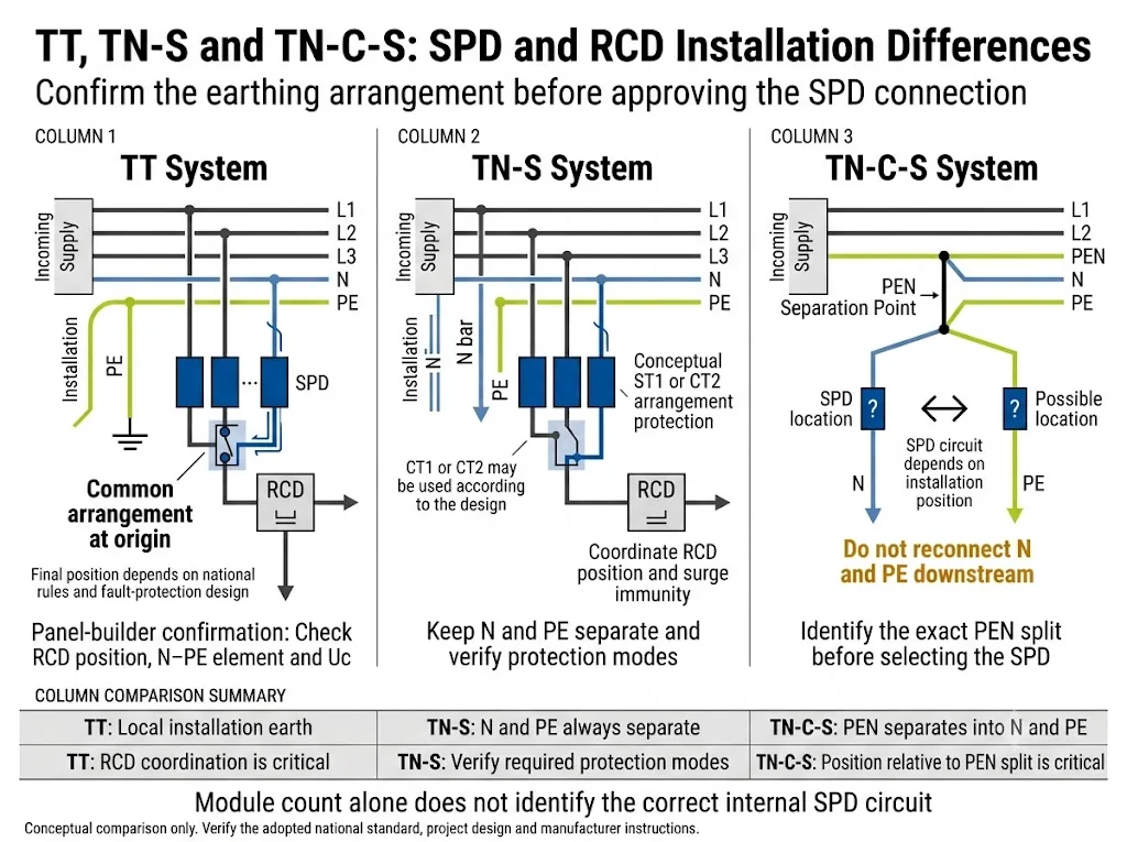
The most important column is “What the panel builder must confirm.”
| System | Main characteristic | Common SPD consideration | What the panel builder must confirm |
|---|---|---|---|
| TT | The installation has a local earth arrangement separate from the supply neutral earth path. | A CT2 arrangement, often described as 1+1 or 3+1, is commonly considered for systems with neutral. | RCD position, N–PE protection element, Uc, fault protection and permitted connection diagram. |
| TN-S | Neutral and PE are separate throughout the installation. | CT1 or CT2 may be possible depending on the required common-mode and differential-mode protection. | Separate N and PE bars, protection modes, RCD position and manufacturer diagram. |
| TN-C-S | A PEN conductor is separated into neutral and PE at a defined point. | The SPD circuit depends on whether the device is installed before or after the PEN separation point. | Exact PEN split position and no downstream reconnection of neutral and PE. |
Engineering conclusion: a product described only as “4P SPD” may use a different internal protection arrangement from a 3+1 or CT2 assembly.
TT system
In TT designs, RCD coordination is critical. A CT2 arrangement uses line-to-neutral protection paths together with a dedicated neutral-to-PE protection element. Manufacturer documentation commonly describes this as a 1+1 or 3+1 circuit.[10]
Do not copy a TN-S diagram into a TT panel without confirming the fault-protection design. See the dedicated TT system SPD guide for deeper selection and wiring considerations.
TN-S system
Neutral and PE are already separate. The design must still confirm which line-to-neutral, line-to-PE and neutral-to-PE protection modes are required.
CT1 and CT2 arrangements should not be treated as interchangeable without checking Uc, Up, temporary-overvoltage behaviour and RCD coordination. See the TN-S system SPD wiring guide.
TN-C-S system
The first design question is not “3+1 or 4P?” It is: where is the PEN conductor separated into PE and N?
Before the separation point, the relevant section behaves as TN-C. After separation, neutral and PE must remain separate. The proposed SPD circuit must match its actual position relative to that point. See the TN-C-S system SPD wiring guide.
Which SPD Parameters Must Be Approved?
Do not approve the model from Imax alone. Each parameter changes a different part of the installation decision.
| Parameter | What it controls | Project approval question |
|---|---|---|
| Uc | Maximum continuous voltage that can be applied to the SPD under normal operation. | Does it match the system voltage, protection mode and earthing arrangement? |
| Up | Declared voltage protection level under the specified test condition. | After conductor voltage is considered, is the installed level suitable for the equipment impulse withstand? |
| Iimp | Type 1 lightning-current duty using the 10/350 µs waveform. | Does it match the lightning protection and current-distribution assessment? |
| In | Nominal discharge-current performance using the 8/20 µs waveform. | Is it suitable for the installation position and expected surge exposure? |
| Isccr or SCCR | Declared short-circuit capability under specified protective-device conditions. | Is it suitable for the prospective short-circuit current at the connection point? |
| Protection modes | The conductor combinations protected by the internal SPD circuit. | Does the circuit match TT, TN-S or the position of the TN-C-S PEN split? |
| Backup protection | Coordination between the SPD and an internal, dedicated or upstream OCPD. | Are device type, rating, breaking capacity and fault-current conditions documented? |
IEC 61643-11:2025 is the current product standard for SPDs connected to AC low-voltage power systems. It is used with the common SPD requirements in IEC 61643-01:2024.[4] IEC 61643-12:2020 provides application principles for SPD selection, location and coordination.[5]
Buyers should verify which standard edition appears on the certificate and which exact models are covered. One certificate should not be assumed to cover every Uc value, pole configuration, protection circuit, remote-contact option or OEM model.
For detailed voltage selection, see the SPD Uc selection guide.
What Should Panel Builders Confirm Before Ordering?
Panel and OEM confirmation checklist
- Nominal system voltage and frequency
- Maximum expected operating voltage
- TT, TN-S, TN-C, TN-C-S or IT arrangement
- Exact PEN separation point where applicable
- Main board, sub-board or equipment-level position
- External lightning protection system information
- Required SPD Type or test class
- Required Iimp, In and Imax values
- Required voltage protection level Up
- Equipment impulse withstand requirement Uw
- CT1, CT2 or other protection arrangement
- Prospective short-circuit current
- Existing upstream fuse or circuit breaker
- SPD maximum permitted backup protection
- RCD position, type and impulse immunity
- Conductor route and terminal capacity
- Available DIN-rail and enclosure space
- Remote signalling requirement
- Required IEC, EN or national certificate
- Exact models covered by the certificate
- Quantity and delivery schedule
- OEM label, packaging and document requirements
The supplier should receive the single-line diagram or a clear conductor description before recommending the protection arrangement. “Three phase, 400 V” alone does not identify the earthing system, RCD position or internal SPD circuit.
What Evidence Should Be Checked Before Model Approval?
Model-specific document verification
The final approval should be based on documents for the exact proposed SPD model, not on a general product-family claim.
- Product datasheet showing Uc, Up, Iimp or In and the internal protection arrangement
- Installation instructions showing permitted conductor sizes and terminal torque
- Maximum backup fuse or circuit-breaker conditions
- Declared short-circuit capability and its protective-device conditions
- Certificate or test-report schedule showing the exact model scope
- Connection diagram for the intended TT, TN-S or TN-C-S position
- Remote-contact data where panel monitoring is required
- Replacement-module reference where a pluggable SPD is specified
LEEYEE should confirm these items against the selected model and the project documents before an OEM label or panel BOM is finalised. CNSPD is LEEYEE’s surge protection-focused platform for global technical buyers.
Pre-Energisation SPD Installation Check
-
Confirm the applicable standard edition.
Record the IEC, EN or national wiring rule used for the project. -
Confirm the actual earthing arrangement.
Compare the incoming conductors with the approved single-line diagram. -
Check the SPD model and circuit.
Verify Uc, Up, discharge ratings, protection modes and certificate scope. -
Measure the effective connection route.
Do not approve conductor length only by visual impression. -
Inspect protected and unprotected conductor routing.
Avoid unnecessary loops and close parallel routing that can recouple surge energy. -
Verify backup protection.
Match the installed fuse or breaker with the manufacturer’s documented conditions. -
Verify RCD coordination.
Check position, impulse immunity and the absence of an unintended downstream N–PE connection. -
Check terminal torque and conductor capacity.
Follow the SPD and panel manufacturer’s instructions. -
Check indication and remote signalling.
Confirm normal status and test the monitoring circuit where provided. -
Complete the panel file.
Record the installed model, wiring diagram, datasheet, certificate and replacement-module reference.
Common Installation Mistakes
| Mistake | Why it matters | Better approach |
|---|---|---|
| Installing the SPD in the nearest spare DIN space | Long conductors increase the installed protection level. | Plan the SPD beside the incoming conductors and PE or PEN bar. |
| Choosing only by 20 kA or 40 kA | Uc, Up, Iimp, circuit and short-circuit conditions may be unsuitable. | Approve the complete electrical specification. |
| Using the same diagram for TT and TN-S | RCD and N–PE behaviour may be incorrect. | Confirm the earthing arrangement before selecting the circuit. |
| Adding an arbitrary SPD MCB | The rating, breaking capacity or operating characteristic may not coordinate. | Follow the exact SPD manufacturer’s backup-protection conditions. |
| Assuming one main SPD protects every remote load | Cable distance and local interference can reduce effective protection. | Review remote boards and sensitive loads separately. |
| Assuming one certificate covers every variant | Different Uc values and internal circuits may be outside the tested scope. | Verify the exact model in the certificate schedule. |
Need to Confirm an SPD Configuration for a Panel?
Send the single-line diagram, system voltage, earthing arrangement, SPD position, prospective short-circuit current, upstream protective device and required SPD ratings.
LEEYEE can review the information for model selection, connection arrangement, backup-protection compatibility and OEM documentation. Final installation approval remains with the responsible electrical designer and the applicable local authority.
Send Your Panel RequirementBuilt to Protect. Trusted to Last.
Frequently Asked Questions
Is IEC 60364-5-534 still the current standard number?
Not as a current standalone IEC publication. IEC 60364-5-534:1997 was replaced. The relevant current reference is IEC 60364-5-53, Clause 534. The old number remains common in searches and older project documents.
Does every SPD connection have to be less than 0.5 m?
The conductors must be kept as short and straight as possible. For a conventional parallel branch arrangement, approximately 0.5 m is a common target for the combined effective route. The measured path and any permitted alternative connection must be verified for the specific panel and manufacturer instructions.
Can thicker cable compensate for long SPD leads?
Not fully. A larger cross-section can improve current-carrying and mechanical performance, but it does not remove the inductive voltage created by an unnecessarily long surge-current path.
Does every SPD need a separate backup fuse or MCB?
No. Backup protection may be internal, dedicated or provided through coordination with an existing upstream device. The decision depends on the exact SPD rating, manufacturer instructions and prospective short-circuit current.
Can an SPD be installed downstream of an RCD?
Yes, but the RCD must have suitable impulse-current immunity and the arrangement must preserve fault protection. The applicable national standard and the RCD datasheet must be checked.
Should every TT panel use a 3+1 SPD?
A CT2 or 3+1 arrangement is commonly considered in TT systems with neutral, especially where RCD coordination is important. It is not a universal automatic choice. The project earthing design and manufacturer’s tested circuit must be confirmed.
Is a four-module SPD suitable for both TN-S and TN-C-S?
Not automatically. Module count does not identify the internal protection modes. In TN-C-S, the SPD position relative to the PEN separation point must also be known.
Is another SPD always required when equipment is more than 10 m away?
No. A distance of approximately 10 m normally triggers an engineering review. Equipment impulse withstand, cable route, local surge sources and coordination with the upstream SPD determine whether another SPD is required.
Can a panel builder approve an SPD only from its Imax rating?
No. Uc, Up, Iimp or In, protection modes, short-circuit capability, backup protection, conductor routing, RCD position and certificate scope must also be checked.
References
- International Electrotechnical Commission. IEC 60364-5-53:2019+AMD1:2020+AMD2:2024 CSV — Low-voltage electrical installations, Part 5-53: Selection and erection of electrical equipment. Official IEC publication page.
- International Electrotechnical Commission. IEC 60364-5-534:1997 — Electrical installations of buildings, Section 534: Devices for protection against overvoltages. IEC lists this publication as replaced by IEC 60364-5-53. Official IEC lifecycle page.
- International Electrotechnical Commission. IEC 60364-4-44:2024 — Low-voltage electrical installations, Part 4-44: Protection against voltage disturbances and electromagnetic disturbances. Official IEC publication page.
- International Electrotechnical Commission. IEC 61643-11:2025 — Surge protective devices connected to AC low-voltage power systems: Requirements and test methods, used with IEC 61643-01:2024 — General requirements and test methods. IEC 61643-11 publication page; IEC 61643-01 publication page.
- International Electrotechnical Commission. IEC 61643-12:2020 — Surge protective devices connected to low-voltage power systems: Selection and application principles. Official IEC publication page.
- Schneider Electric Electrical Installation Guide. Connection of Surge Protection Device and Cabling Rules of Surge Protection Device. Technical guidance covering installed Up, conductor inductance, the 50 cm connection principle and panel conductor routing. Connection guidance; Cabling guidance.
- DEHN. Surge Protection in Low-Voltage Switchgear Assemblies. White paper covering SPD location, connection-wire voltage drop, approximately 0.5 m conductor paths, remote equipment beyond approximately 10 m, backup protection and short-circuit capability. Technical white paper.
- Schneider Electric Electrical Installation Guide. SPD and Protection Device Coordination Table. Guidance covering external short-circuit protective-device coordination and impulse-resistant RCDs downstream of earth-leakage protection. Technical guidance page.
- Schneider Electric Electrical Installation Guide. Common Characteristics of SPDs According to the Installation Characteristics and Propagation of a Lightning Wave. Guidance covering Uc, protection modes, earthing arrangements and downstream SPD review beyond approximately 10 m. Earthing-system guidance; Protection-distance guidance.
- BTicino / Legrand. Modular Surge Protective Devices — Product and Installation Information, IDP000018EN_05. Manufacturer guidance illustrating CT2 arrangements for TT and TN-S systems, RCD coordination and short SPD connections. Manufacturer technical document.
This article summarises engineering and procurement considerations in original wording. It does not reproduce the IEC standard and does not replace the purchased standard, national wiring rules, utility requirements, manufacturer instructions, project calculations or approval by the responsible electrical designer.
