
Crane control panels combine power distribution, variable frequency drives (VFDs), PLC control, sensors, limit switches and communication interfaces. Because cranes often operate with long cables, moving equipment and outdoor exposure, surge protection should be evaluated as a complete control-system architecture rather than as one SPD at the incoming power point.
This guide focuses specifically on surge protection for crane control panels, overhead cranes, gantry cranes and related lifting equipment. It is written for crane OEMs, control-panel builders, industrial system integrators and maintenance teams that need to decide which circuits require protection and what information must be confirmed before selecting an SPD.
A crane control panel normally requires separate surge-protection evaluation for the incoming AC supply, VFD supply, low-voltage control circuits and external signal or communication lines. The final SPD configuration depends on system voltage, earthing arrangement, cable routing, installation environment and project-specific electrical design.
| Crane Section | Protection Consideration | Buyer Information Required |
|---|---|---|
| Main AC supply | AC SPD at the control-panel supply side | Voltage, phase, earthing arrangement |
| VFD input side | AC surge protection coordinated with the drive system | VFD model, supply voltage, installation position |
| PLC and 24 V DC control | DC control-circuit protection evaluation | Control voltage, wiring route and interface |
| Limit switches, sensors and communications | Signal or interface SPD where required | Signal type, cable length and external exposure |
The key point is simple: one AC SPD cannot automatically protect every circuit inside and outside a crane control cabinet.
For OEM crane control panels, the supplier needs the actual electrical architecture. System voltage, earthing, VFD arrangement, control voltage, signal interfaces and installation location affect the final SPD configuration.
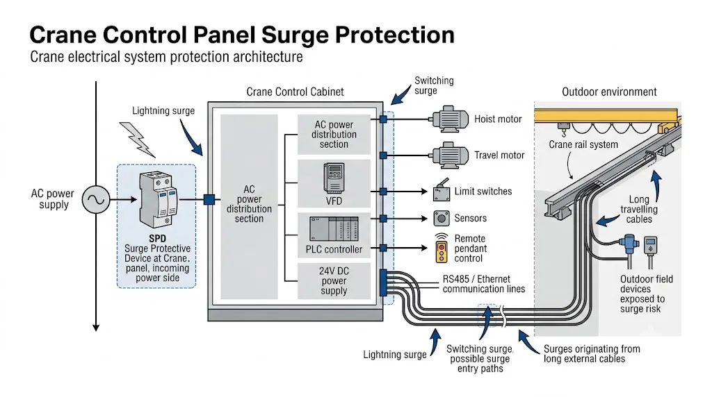
The architecture above shows why crane surge protection is normally a multi-point engineering decision. Power lines and field-control lines can enter the same cabinet through different electrical paths, so each interface should be evaluated according to its own voltage level and function.
Table of Contents
Why Crane Control Panels Need Surge Protection Evaluation
A crane control panel is more than a motor-control enclosure. Modern crane systems may contain VFDs, PLC modules, contactors, control relays, 24 V DC power supplies, communication equipment and safety-related field devices. These circuits do not all have the same surge withstand characteristics.
Potential surge or transient paths can include:
- Incoming power cables: external overvoltage disturbances can enter through the crane electrical supply.
- Long travelling cables: moving or rail-mounted crane systems often use extended cable routes between the main supply, trolley and field equipment.
- Switching operations: motors, contactors and power-electronic equipment can create switching transients within the electrical system.
- External control wiring: limit switches, sensors, remote controls and communication lines may provide separate paths into the cabinet.
The protection design should follow the actual electrical paths entering and leaving the crane control cabinet. A device installed on one circuit cannot be assumed to protect another circuit with a different voltage level or interface.
Crane Types Where SPD Selection Is Commonly Considered
| Crane Application | Typical Electrical Concern | Protection Focus |
|---|---|---|
| Overhead travelling crane | Travelling cables, motor switching and distributed controls | Incoming power plus field-control interfaces |
| Gantry crane | Outdoor exposure and long rail-side wiring | Power, control and communication entry points |
| Port crane | Humidity, salt atmosphere and extended field cabling | Electrical protection plus environmental suitability |
| Automated crane system | PLC, sensors, encoders and communication networks | Power and signal-interface coordination |
These are engineering examples, not universal installation rules. The final requirement depends on the crane design, project risk assessment and applicable electrical standards.
Where Should SPD Be Installed in a Crane Control Panel?
SPD installation should follow the actual crane electrical architecture. The most important question is not simply “Where can an SPD fit?” but “Through which conductors can a damaging transient reach the equipment?”
1. Incoming AC Power Side
The incoming AC supply is normally the first protection point to evaluate. The SPD must be suitable for the actual system voltage, phase arrangement and earthing system. Selection must also consider the installation position and coordination with upstream or downstream protective devices.
When requesting an AC SPD for a crane control cabinet, provide the nominal system voltage, phase configuration, earthing arrangement and the location where the SPD will be installed.
2. VFD Supply Side
Crane hoist and travel drives often use variable frequency drives. Surge protection for a VFD system should be evaluated on the supply side and coordinated with the drive manufacturer's installation requirements.
The switching waveform on a VFD motor output is not the same engineering phenomenon as an external surge. Therefore, an SPD should not be added to the VFD output simply because the drive produces fast voltage transitions. Any device installed around the drive output must be specifically approved for that application by the equipment manufacturer and project designer.
3. PLC and 24 V DC Control Circuits
PLCs and low-voltage control circuits may be supplied through a 24 V DC power supply or another control voltage. These circuits should be evaluated separately from the main AC supply because the operating voltage and acceptable protection level are different.
A DC SPD must match the actual control voltage and circuit characteristics. The correct model should be confirmed from the control schematic rather than inferred from the crane's main supply voltage.
4. Limit Switches, Sensors and Field Devices
Limit switches, proximity sensors, encoders and other field devices may be located far from the control cabinet. Long external cable routes can create a separate surge path into PLC or I/O terminals.
Signal protection should be selected according to the signal voltage, interface type, current, bandwidth or data characteristics where relevant. A mains AC SPD is not a substitute for a signal-line SPD.
5. Pendant and Remote-Control Circuits
Wired pendant controls and remote-control receivers should be reviewed according to their actual connection method. If a control line leaves the protected cabinet and travels through an exposed or long route, that interface may require separate protection evaluation.
Power circuits, DC control circuits and communication interfaces operate at different voltage levels and may use different protection principles. Each cable entering or leaving the crane control system should be reviewed according to its function.
SPD Selection for Crane Power, VFD and Control Circuits
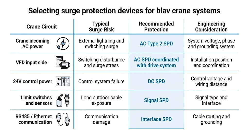
The comparison above separates the major crane circuits because each one requires different selection information. This is especially important for OEM control-panel projects, where the SPD must be confirmed before the panel layout and wiring are finalized.
AC Power SPD Selection
For the crane incoming supply, confirm:
- nominal system voltage;
- maximum expected operating voltage where relevant;
- single-phase or three-phase arrangement;
- earthing system;
- required SPD type and installation location;
- coordination with backup protection and other SPDs in the installation.
A higher SPD voltage rating does not automatically mean better protection. The SPD must remain suitable for the actual operating voltage while providing an appropriate protection level for the downstream equipment.
VFD Protection Considerations
For a crane with VFD-controlled hoist or travel motors, confirm the drive input voltage, upstream distribution arrangement and whether another SPD is already installed in the supplying panel.
The final arrangement should follow the VFD manufacturer's documentation and the project electrical design. Do not assume that a generic SPD location is suitable for every drive system.
Control and Communication Protection
Control and communication circuits require interface-specific selection. Examples can include PLC I/O, RS485, Ethernet and low-voltage sensor circuits.
The SPD must be compatible with the normal signal voltage and interface characteristics. For communication circuits, additional parameters such as transmission characteristics and connection method may also need confirmation.
Outdoor Rails, Long Cables and Field Equipment
Outdoor and travelling crane systems often have a greater amount of field wiring than a fixed indoor control panel. Long cable runs may connect the main cabinet to trolley equipment, remote I/O, sensors, limit switches or operator controls.
This makes cable routing an important part of the surge-protection review. A practical engineering assessment should identify:
- which cables leave the main control cabinet;
- how far they travel;
- whether they run outdoors or alongside large power conductors;
- where field devices are grounded or bonded;
- whether the cable enters another local enclosure before reaching the device.
Where a field line creates a separate exposure path, protection may be required at one or both ends depending on the circuit, system design and applicable project requirements. This must be confirmed case by case.
Port, High-Humidity and Corrosive Environments
Port cranes and other outdoor lifting equipment may operate in humid, saline or corrosive environments. These conditions do not change the basic electrical purpose of an SPD, but they can affect enclosure selection, terminals, mounting conditions and long-term maintenance requirements.
The SPD itself and the surrounding installation should be suitable for the environmental conditions specified by the project. Do not assume that an indoor DIN-rail installation condition is automatically suitable for an exposed outdoor location.
For port or outdoor crane projects, provide the installation environment together with the electrical parameters. Environmental conditions can affect the enclosure and installation method even when the electrical SPD rating is otherwise suitable.
Grounding and Equipotential Bonding Matter
SPD performance depends on the complete installation, not only the device specification. Connection conductors, grounding and equipotential bonding can influence the residual voltage that reaches protected equipment.
SPD connection conductors should be kept as short and direct as practical according to the applicable installation rules and project design. Long or unnecessarily looped conductors can increase inductive voltage during a surge.
The exact grounding and bonding arrangement must follow the crane electrical design and applicable standards. It should not be improvised solely from a general article.
Common Crane SPD Selection Mistakes
| Mistake | Why It Is a Problem | Better Engineering Approach |
|---|---|---|
| Protecting only incoming AC power | External signal and communication paths may remain exposed | Review every cable entering or leaving the control system |
| Selecting SPD from motor kW only | Motor power does not define SPD voltage or interface type | Use system voltage, earthing and circuit function |
| Using a power SPD on a signal circuit | Electrical characteristics may be incompatible | Select an SPD designed for the specific signal interface |
| Ignoring cable routing | Long field cables may create an additional surge path | Review field-device distance and cable exposure |
| Choosing a higher voltage rating “for safety” | Higher continuous voltage capability does not automatically provide a lower protection level | Match the SPD to the actual system operating conditions |
SPD Status Checks and Maintenance Planning
Crane maintenance teams should include SPD condition checks in the electrical maintenance plan. Inspection frequency should follow the equipment maintenance programme, manufacturer instructions and site conditions.
- Check the visual status indicator where the SPD provides one.
- Inspect the module and terminals for visible overheating or damage.
- Confirm that conductors and terminal connections remain secure according to the maintenance procedure.
- Record replacement dates and module references.
- Where remote status contacts are used, confirm that the monitoring circuit is functioning.
A failed or end-of-life indication should be handled according to the SPD manufacturer's instructions and the project's electrical safety procedure.
Before Ordering: Crane Control Panel SPD Checklist
- crane type: overhead, gantry, port, hoist or other lifting equipment;
- nominal AC system voltage and phase arrangement;
- earthing system;
- VFD input voltage and model where applicable;
- PLC and control-circuit voltage;
- limit-switch, sensor and encoder signal types;
- RS485, Ethernet or other communication interfaces;
- approximate external cable length and cable routing;
- indoor, outdoor, humid, port or corrosive environment;
- available DIN-rail or cabinet installation space;
- required standards, certificates or technical documents;
- OEM label, packaging or documentation requirements.
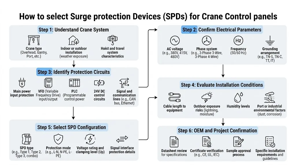
The workflow above turns the crane SPD selection process into a practical sequence: first understand the crane electrical system, then identify the exposed circuits, confirm installation conditions and only then finalize the SPD configuration.
Send your crane control-panel voltage, earthing arrangement, VFD information and protected interfaces. LEEYEE can review the available information and help identify a suitable SPD configuration for OEM crane panels and industrial lifting applications. Final selection should still be confirmed against the project drawings and equipment requirements.
Frequently Asked Questions
Does every crane control panel need an SPD?
Not every crane can be given the same answer without reviewing the installation. The need and SPD configuration depend on the electrical system, exposure conditions, equipment sensitivity, applicable standards and project risk assessment.
Where should an SPD be installed in an overhead crane control cabinet?
The incoming AC supply is normally one of the first points to evaluate. VFD supply circuits, low-voltage controls and external field interfaces may require additional protection depending on the crane architecture and cable exposure.
Can one Type 2 AC SPD protect the whole crane?
Not necessarily. A Type 2 AC SPD protects the circuit to which it is correctly connected. It does not automatically provide suitable protection for 24 V DC controls, RS485, Ethernet, sensors or other signal interfaces.
Should an SPD be installed on the VFD output to the crane motor?
Do not assume so. A VFD output contains fast switching waveforms, and equipment connected there must be specifically suitable for that environment. Follow the VFD manufacturer's documentation and the project design before installing any surge-protection device on the drive output.
Do limit switches and crane sensors need separate surge protection?
They may, especially where long or externally routed cables connect field devices to sensitive control electronics. Selection depends on the signal type, voltage, wiring arrangement and exposure conditions.
What information should a crane OEM provide to an SPD supplier?
At minimum, provide the power-system voltage, phase arrangement, earthing system, VFD details, control voltage, external signal interfaces, cable conditions and installation environment. These details allow the supplier to evaluate the actual circuits rather than guessing from crane size or motor power.
