
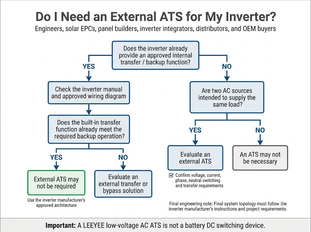
Do you need an automatic transfer switch for an inverter? Not always. Many inverter-chargers and hybrid inverters already include an internal transfer function, a dedicated backup or EPS output, or a manufacturer-specific backup interface. An external ATS becomes useful when the approved system design needs a separate device to transfer a load between two AC sources or provide an additional automatic bypass path.
Check the inverter manual before selecting an external ATS. If the inverter already provides the required automatic transfer function, another ATS may be unnecessary. If grid AC and inverter AC output must independently supply the same transferred load, or the load needs an automatic alternative path when inverter output is unavailable, an external ATS may be appropriate. The final arrangement must follow the inverter manufacturer's approved wiring diagram and the project's electrical requirements. [2][3]
| Inverter system | External ATS? | Main confirmation |
|---|---|---|
| Inverter with an internal AC transfer function | Often not required | Confirm that the built-in function meets the required backup operation. |
| Hybrid inverter with dedicated EPS / backup output | Depends | Follow the manufacturer's approved backup topology. |
| Grid AC and inverter AC can feed the same load | May be required | Check voltage, current, phase, neutral treatment and transfer logic. |
| Backup load needs grid supply if inverter output fails | May be useful | Confirm that an external bypass arrangement is permitted. |
| Battery DC circuit requires switching | Not this AC ATS | Use a device specifically rated for the DC circuit. |
Buyer priority: identify the inverter's existing transfer architecture before choosing ATS current or pole count.
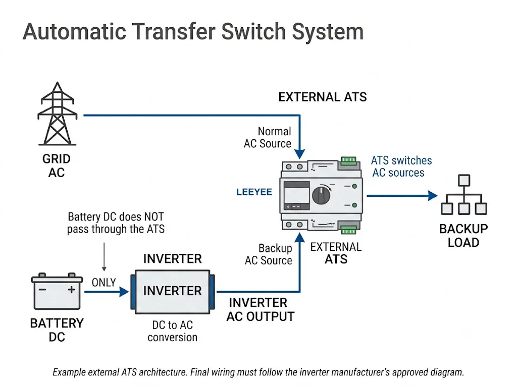
Table of Contents
Does your inverter already have a transfer function?
This question should come before amperage, pole count or ATS model selection. Some inverter-chargers already pass acceptable AC input through to their AC output and switch to inverter operation when the incoming AC source is no longer acceptable. Victron documents this operating principle for its MultiPlus inverter-charger family. [2]
Other hybrid systems use a dedicated external backup device designed by the inverter manufacturer. SMA, for example, documents Backup Select as an automatic transfer switching device intended for specific compatible inverter models rather than as a universal accessory for every inverter. [5]
Engineering meaning: “Hybrid inverter” does not define one universal wiring architecture. Two inverters with similar power ratings can require different transfer, neutral and backup arrangements.
Before ordering an ATS, check the inverter manual for terms such as AC input, AC output, EPS output, backup output, transfer relay, bypass, backup interface and grid connection.
Inverter ATS wiring diagram: what each connection means
For a typical external ATS application, the key relationship is simple: the ATS transfers the load between AC sources. It does not normally sit between the battery and inverter in the DC circuit.
| Connection | Typical role | What must be verified |
|---|---|---|
| Grid AC → ATS | One transferable AC source | Voltage, frequency, phase and protective device. |
| Inverter AC output → ATS | Alternate AC source | Approved output, current capability and inverter operating mode. |
| ATS output → load | Transferred load circuit | Maximum load current and required continuity. |
| Battery DC → inverter | DC energy source | Battery-system DC protection and isolation requirements. |
This is an architecture explanation, not a universal terminal wiring instruction. Terminal numbering, neutral connections, protective devices and control wiring must follow the exact ATS documentation, inverter manual and approved project diagram.
When does an external ATS make sense?
Two independent AC sources must feed one transferred load
This is the clearest ATS application. If grid AC and inverter AC output are both intended to supply the same load at different times, the system needs a controlled transfer arrangement rather than an unintended connection between the sources.
The inverter does not provide the required automatic changeover
An external ATS may provide the source-selection function when the inverter itself does not. This still requires confirmation that the inverter manufacturer permits the proposed topology.
The load needs a fallback path when inverter output fails
An external ATS can also serve a different purpose: protecting the load against loss of the inverter's backup output. Solis documents a model-specific application where an external ATS transfers backup loads to the grid if an inverter fault or alarm causes the backup output to shut down. [3]
That Solis arrangement is useful as an engineering example, but it must not be copied blindly to other inverter brands or models.
The panel builder needs an independent transfer function
For solar EPCs, system integrators and control-panel manufacturers, a separate ATS may be appropriate when the project's one-line design intentionally separates the source-transfer function from the inverter. The electrical design should be confirmed before the panel BOM is frozen.
When may an external ATS be unnecessary?
An additional ATS may add no useful function when the inverter already provides the approved source-transfer behaviour required by the project.
- The inverter already has a suitable internal AC transfer relay.
- A dedicated EPS or backup output already supplies the required backup loads.
- The manufacturer specifies its own backup interface or transfer device.
- The proposed external ATS would duplicate an existing transfer path without solving another system requirement.
Buyer meaning: do not treat an ATS as a mandatory inverter accessory. First identify what transfer function already exists and what additional problem the external ATS is expected to solve.
ATS vs inverter bypass vs UPS
| Function | Main job | Buyer question |
|---|---|---|
| ATS | Transfers a load between two eligible power sources. | Which AC sources, current, voltage and poles? |
| Inverter bypass | Routes power around part or all of the inverter conversion path, depending on equipment design. | Is the bypass internal, manual, automatic or external? |
| UPS function | Maintains specified load supply through a defined energy-storage and power-conversion architecture. | What interruption can the load tolerate? |
| Battery disconnect | Switches or isolates a DC battery circuit. | What DC voltage, current and breaking duty apply? |
Solis specifically distinguishes its integrated manual bypass from an optional external automatic transfer arrangement in its documented application. This is a good example of why “bypass” and “ATS” should not automatically be treated as the same function. [3]
What does open transition mean for inverter backup?
The standard compact LEEYEE ATS discussed on this page is an open-transition device. Open transition means break before make: the connected source is disconnected before the alternate source is connected.
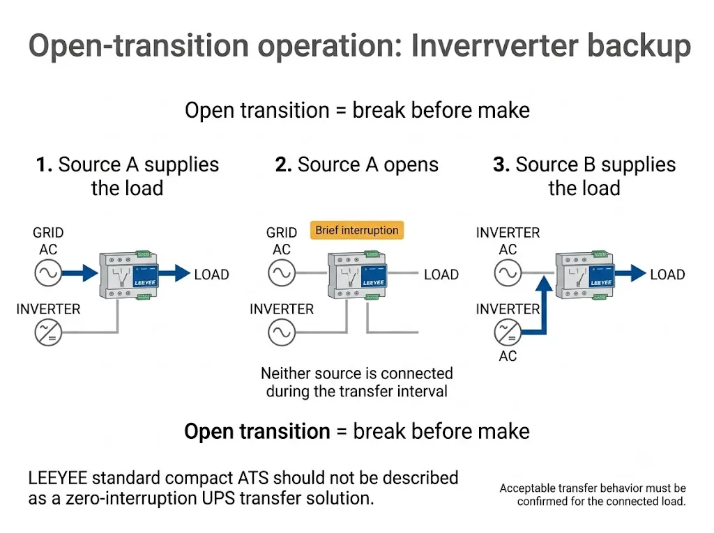
This means a standard open-transition ATS should not be presented as a zero-interruption UPS solution. The load's ability to tolerate the transfer interval must be checked against the actual ATS performance, inverter behaviour and load requirement.
For sensitive loads: if the project specifies seamless transfer, a defined maximum interruption time or closed-transition operation, confirm that requirement before selecting the ATS. Do not infer those capabilities from the words “automatic transfer switch.”
2P or 4P: which LEEYEE ATS fits the inverter system?
The LEEYEE compact ATS models shown for this application include 2P and 4P configurations. Pole selection is not simply a matter of reading the number of phases. The main engineering question is whether the neutral conductor must be switched together with the live conductors.
A single-phase project may use a 2P arrangement where line and neutral are switched. A three-phase project may use a 4P arrangement where L1, L2, L3 and neutral are switched. The final decision must still follow the inverter topology, earthing arrangement, neutral treatment, applicable project rules and the inverter manufacturer's approved connection method.
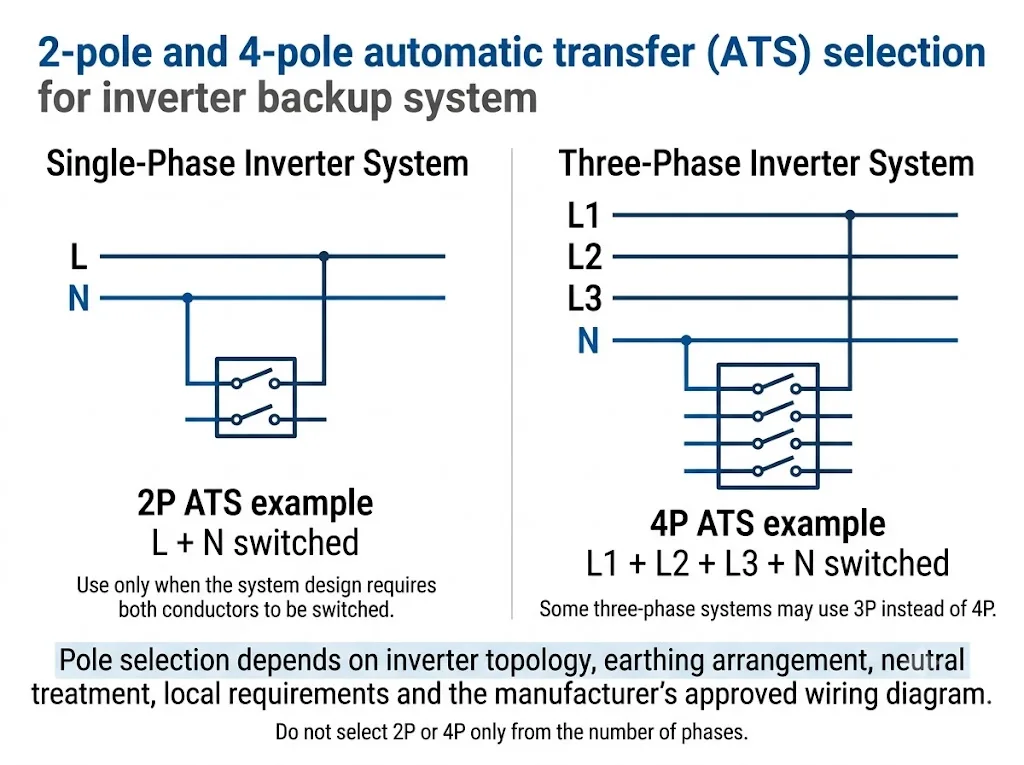
Neutral switching cannot be decided from phase count alone. Manufacturer-specific backup systems demonstrate this clearly. SMA documents one Backup Select design in which the neutral conductor is not switched, showing why neutral treatment must follow the approved system architecture rather than a universal inverter rule. [5]
How should you size an ATS for an inverter?
Do not select the ATS from PV-array wattage alone. The ATS carries the current flowing through the transfer point. The relevant values are the AC source capability, transferred-load current and the project's protective-device and short-circuit design.
- Confirm the inverter architecture. Identify AC input, AC output, EPS or backup output, internal transfer function and any manufacturer-specific interface.
- Confirm both proposed AC sources. Check voltage, frequency, phase configuration and whether the sources are permitted in the intended transfer topology.
- Determine maximum transferred current. Review inverter AC output or pass-through limits together with the actual load design current.
- Select the required 2P or 4P arrangement. Determine whether neutral switching is required and confirm that the chosen LEEYEE model matches the approved conductor arrangement.
- Confirm transfer behaviour. Make sure open transition is acceptable for the connected load.
- Verify protection and fault conditions. Coordinate the ATS with upstream and downstream protection and the prospective short-circuit conditions.
- Approve the one-line diagram before ordering. For inverter projects, “current + poles” is not enough information for reliable ATS selection.
What can go wrong if the ATS is selected incorrectly?
- Wrong system topology: the ATS arrangement can conflict with the inverter's approved transfer or backup logic.
- Incorrect neutral treatment: unnecessary or missing neutral switching can affect the intended earthing arrangement.
- Unexpected interruption: an open-transition ATS may not suit sensitive loads that require another continuity level.
- Wrong current basis: PV or inverter kW alone does not define the actual current through the transfer point.
- Incorrect bypass assumption: a general ATS should not automatically replace a manufacturer-specific backup interface.
- DC misuse: an AC ATS should not be inserted into a battery DC circuit without a specific approved DC rating.
Where the LEEYEE compact ATS fits
The LEEYEE product shown below is a compact dual-source low-voltage AC automatic transfer switch. The pictured units are marked ATS-2P63 and ATS-4P63 and include A/B source connections, load output, Auto/Manual operation and front status indication.
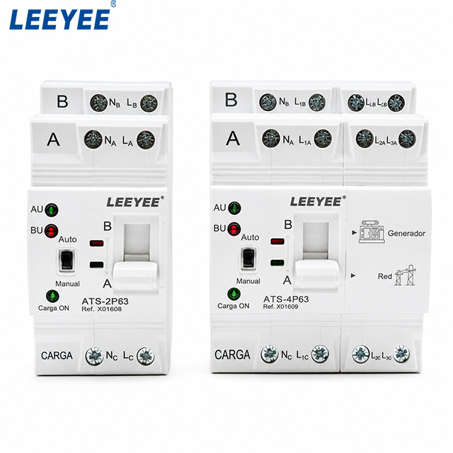
In an inverter backup application, one eligible AC source may be the grid and the other may be the inverter AC output, provided that the inverter manufacturer permits that topology and the electrical ratings are suitable. The product should therefore be evaluated as a dual-source AC transfer device rather than described as a dedicated “solar inverter ATS.”
Important: the front markings and A/B source labels shown on the product image should not be used to assume a universal source priority or terminal assignment for every inverter project. Confirm source priority, control logic and terminal functions from the exact LEEYEE model documentation before wiring.
The standard LEEYEE ATS discussed here should not be described as a battery DC switch, UPS, zero-interruption static transfer switch, closed-transition ATS or large bypass-isolation cabinet.
Project confirmation: compatibility with a particular inverter brand or model is not assumed. The inverter manual, approved wiring diagram, source voltage, load current, phase configuration and neutral requirement should be reviewed before final ATS selection.
What should you send before requesting an ATS recommendation?
- Inverter manufacturer and exact model
- Inverter manual or wiring diagram
- Grid AC voltage and frequency
- Inverter AC / EPS output voltage
- Single-phase or three-phase system
- Maximum inverter output or pass-through current
- Maximum transferred load current
- Required 2P or 4P configuration
- Earthing and neutral-switching requirement
- Required transfer behaviour
- Applicable project standard or approval requirement
- Quantity and OEM / private-label requirement
Need to confirm whether a LEEYEE compact ATS fits your inverter system?
Send the inverter model, wiring diagram, AC voltage, phase configuration and expected transferred current. LEEYEE can review the AC transfer requirement before model selection.
Frequently asked questions
Do I need an ATS if my inverter already has a transfer switch?
Not necessarily. If the inverter's built-in transfer function already performs the required source changeover and supports the intended load arrangement, another ATS may be unnecessary. Check the inverter manual before adding an external transfer device. [2]
Can a LEEYEE ATS switch between grid power and inverter output?
It may be used for that AC source-transfer function when the inverter manufacturer permits the architecture and the selected ATS model matches the required voltage, current, pole configuration and transfer behaviour. Do not assume compatibility from source type alone.
Does every hybrid inverter need an external ATS?
No. Some systems have internal source transfer, while others use a dedicated manufacturer-specific backup device or may require an external transfer arrangement. The approved inverter documentation should determine the starting point. [2][5]
Can an ATS automatically bypass a failed inverter?
It can in a system specifically designed for that function. Solis documents one inverter-specific configuration where an external ATS transfers backup loads to grid power if inverter backup output is lost. That example should not be treated as a universal wiring method for all inverters. [3]
Can I connect the battery directly to this ATS?
Not for the AC application discussed on this page. The battery circuit is DC and requires switching and protection equipment specifically rated for its DC voltage, current and breaking duty.
Is inverter bypass the same as an ATS?
No. An ATS selects between eligible power sources. An inverter bypass routes power around part or all of the inverter path according to the equipment design. A particular backup system may use both functions, but they are not automatically interchangeable.
Does an open-transition ATS provide zero-interruption transfer?
No such assumption should be made. Open transition is break-before-make and includes a transfer interval. If the connected load requires a defined maximum interruption time or seamless continuity, that requirement must be verified separately.
Should I choose the 2P or 4P LEEYEE ATS?
The choice depends on the phase arrangement and whether the neutral must be switched. A 2P unit may suit a single-phase arrangement where line and neutral are transferred, while a 4P unit may suit a three-phase arrangement requiring L1, L2, L3 and neutral transfer. Confirm the inverter topology and neutral requirement before ordering.
Should ATS size be selected from inverter kW?
Not from kW alone. Determine the maximum AC current that can actually flow through the transfer point and confirm it against the ATS rating, load design and protection requirements.
References
- International Electrotechnical Commission (IEC). IEC 60947-6-1:2026 — Low-voltage switchgear and controlgear — Part 6-1: Multiple function equipment — Transfer switching equipment . Use the applicable edition and model-specific manufacturer documentation for project approval.
- Victron Energy. MultiPlus 2kVA 230V — Operation . Official documentation describing AC input passthrough and inverter operation when incoming AC is not within specification.
- Solis North America. External Automatic Transfer Switch (ATS) for Backup Load Protection . Model-specific guidance showing an external ATS used to transfer backup loads to grid if inverter backup output is unavailable.
- SolarEdge. Official Backup Interface documentation and installation instructions for compatible SolarEdge backup systems. Verify the current manual and compatible inverter/battery combination for the specific project.
- SMA Solar Technology AG. SMA Backup Select — Intended Use . Official documentation describing a manufacturer-specific automatic transfer switching device and its approved conductor arrangement.
- LEEYEE. What Is an Automatic Transfer Switch? How ATS Works & How to Choose . Supporting overview of ATS operating principles and general source-transfer selection.
