
Automatic transfer switch (ATS) time delay settings affect when a utility problem becomes a real transfer event, when a generator-start sequence begins, when the load can move to the alternate source, when utility power is trusted again, and when the generator can stop.
For compact utility-generator ATS applications, however, not every timing function is necessarily adjusted directly on the transfer switch itself. Some functions may be fixed in the ATS logic, handled by the generator controller, or managed by an external control system.
This guide therefore explains system-level ATS timing and commissioning logic. It does not assume that every compact ATS provides the same programmable timers as a large programmable transfer-switch controller.
IEC 60947-6-1:2026 is the current IEC product standard covering transfer switching equipment, including automatic transfer switching equipment and stand-alone ATS controllers.[1] Actual delay functions and ranges vary between controller families, so final settings must be confirmed against the installed ATS, generator, load and project sequence.[2][4]
Table of Contents
Product Scope for This Guide
LEEYEE's standard ATS offering for this application is a compact integrated transfer switch used between normal and alternate power sources. The product family includes compact 2P and 4P configurations for different system requirements.
- This article applies to utility-generator transfer system planning and commissioning.
- It does not imply that every delay described below is independently adjustable on the compact ATS itself.
- Where a project requires programmable start, transfer, retransfer or cooldown logic, confirm whether that function is provided by the selected ATS, the generator controller or an external controller.
- LEEYEE's standard compact ATS application is based on open-transition source transfer; advanced closed-transition or bypass functions require separate engineering confirmation.
Quick Answer: How Should ATS Time Delays Be Set?
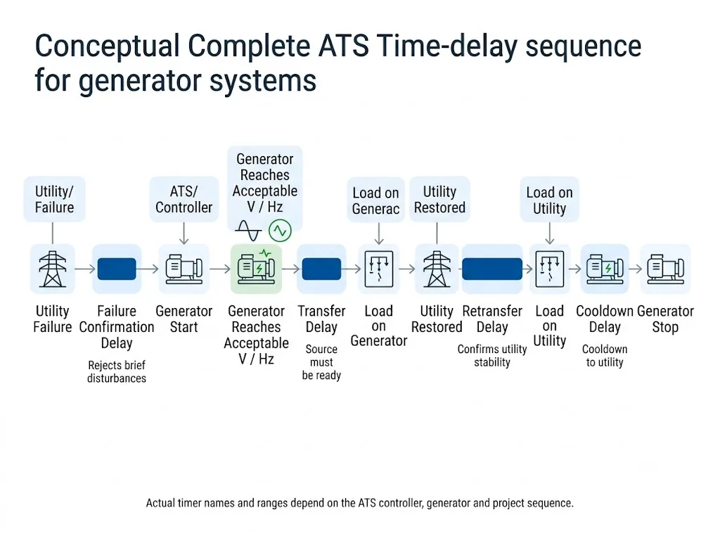
First identify where each timing function is implemented. Then use each delay to prove one condition before the system moves to the next step. The utility-failure delay should avoid reacting unnecessarily to short disturbances. The generator-transfer sequence should wait until the alternate source is acceptable. The retransfer delay should confirm that normal power has recovered reliably. The cooldown period should follow the intended generator shutdown sequence.[2][3]
Do not copy one group of “standard ATS delay settings” from another project. Current manufacturer documentation shows different timer ranges, defaults and control logic between ATS families.[2][4]
Where Does the Time Delay Actually Come From?
In a generator backup system, timing can be distributed across several devices. This is especially important when a compact ATS is integrated with a separate generator controller.
| Timing Function | May Be Handled By | What the Buyer Should Confirm |
|---|---|---|
| Utility failure confirmation | ATS sensing/control logic or external controller | Whether the delay is fixed, adjustable or managed outside the ATS |
| Generator start delay | ATS controller, generator controller or external control logic | Which device actually initiates the generator-start sequence |
| Generator source qualification | ATS sensing logic and/or generator control system | How acceptable voltage and frequency are determined for the project |
| Retransfer delay | ATS controller or external automation logic | Whether auto-return is required and how normal-source stability is confirmed |
| Generator cooldown | Generator controller, ATS controller or external control logic | Which device owns the stop command and cooldown sequence |
The ATS may be the device that transfers the load, while the generator controller handles part of the engine start and shutdown sequence. Always confirm the complete control architecture instead of assuming every timer belongs to the ATS.
The Five Timing Stages to Coordinate in a Generator ATS System
These are the main system timing stages that usually need to be understood during generator ATS commissioning. They are system functions, not a promise that all five appear as adjustable menus on every compact ATS.
The most useful question is “What condition must be confirmed before the system moves to the next stage?”
| Timing Stage | What It Confirms | Main Risk If Incorrect |
|---|---|---|
| Utility failure confirmation | The normal-source problem persists long enough to begin the backup sequence | Unnecessary generator starts or unnecessarily slow response |
| Generator start and source qualification | The generator is started and the alternate electrical source becomes acceptable | Attempting transfer before the alternate source is ready |
| Transfer to generator | The transfer sequence can proceed to the alternate source | Premature transfer or an unnecessarily long outage |
| Utility return / retransfer | Normal power has recovered and remains acceptable | Premature return to an unstable source or unnecessary generator runtime |
| Generator cooldown / stop | The load has returned to normal power before the generator stop sequence completes | Unsuitable shutdown coordination or excessive unloaded running |
ATS Time Delay vs Transfer Switching Time: They Are Not the Same
ATS time delay is an intentional control waiting period before a particular system action. Examples include waiting before generator start, before retransfer to utility, or before generator shutdown.
Transfer switching time is the switching interval associated with changing the connected source after the transfer logic permits the operation.
ATS / System Time Delay
An intentional control period used to confirm source conditions or coordinate the generator sequence. Depending on the design, it may exist in the ATS, generator controller or external automation.
Transfer Switching Time
The switching interval after the control system permits a source change. It does not automatically include generator crank time, source qualification or other intentional delays.
A compact ATS can have a fast switching mechanism while the complete utility-to-generator restoration process still takes longer because the generator must start and become electrically acceptable first.
1. Utility Failure Confirmation
A generator backup system should distinguish between a genuine source failure and a short disturbance that does not justify a full transfer sequence.
In highly programmable ATS platforms, this may appear as an adjustable generator-start or source-failure timer. In a compact ATS system, the same function may be fixed in the ATS logic or handled elsewhere in the control architecture.
Schneider TransferPacT Active Automatic provides one example of a programmable architecture: its T7 Genset Start Delay is adjustable from 0 to 120 seconds with a 3-second default.[2] This is a reference example only and does not imply that a LEEYEE compact ATS uses the same timer or adjustment range.
2. Generator Running Does Not Automatically Mean Generator Ready
A running engine and an acceptable alternate electrical source are not the same condition. The generator still needs to establish voltage and frequency suitable for the intended system before the load is transferred.
Some programmable ATS controllers monitor target-source voltage and frequency during their transfer logic. Schneider documents this type of source measurement within its T2 transfer sequence.[2]
Record when the generator starts running and when the alternate source becomes electrically acceptable. Do not assume those events occur at the same moment.
If the generator is already running but the load has not transferred, check source qualification, the selected ATS logic, generator controls and any external permissive conditions before assuming that the switching mechanism is faulty.
3. Transfer-to-Generator Timing
Once the alternate source is acceptable, the transfer system determines when the load can move from the normal source to the generator source.
On a programmable controller, this may include an adjustable confirmation or transfer delay. Schneider TransferPacT Active Automatic, for example, lists T2 Transfer Delay from 0 to 1800 seconds with a 3-second default.[2]
Schneider, Cummins and other controller examples in this article are included to explain industry timing logic. They do not mean that the LEEYEE compact ATS provides the same menus, timer ranges or programmable functions. Confirm the selected LEEYEE model and project control requirements before ordering.
If the system transfers too early
Confirm whether the generator source has actually satisfied the required electrical acceptance conditions. Do not compensate for unstable generator output only by changing ATS timing.
If the system transfers too late
Measure where the elapsed time is being consumed. The delay may come from generator starting, source qualification, ATS logic or an external controller.
4. Utility Recovery and Retransfer Timing
Utility voltage appearing again does not always mean the load should immediately return to normal power. A system may intentionally confirm that utility power remains acceptable before retransfer.
In Schneider TransferPacT Active Automatic, T6 is used as a retransfer delay and can be cancelled if the normal source becomes abnormal again during the confirmation period.[2][3]
This type of programmable logic is useful as an engineering reference. For a compact ATS project, confirm whether retransfer timing is fixed, adjustable or managed by another controller.
5. Generator Cooldown and Stop Timing
After the load returns to normal power, many generator systems continue to run the generator unloaded before the stop command is completed.
The cooldown function may belong to the generator controller, ATS controller or another part of the system logic. Therefore, a buyer should not assume that generator cooldown is necessarily programmed inside the compact transfer switch.
As a programmable-controller example, TransferPacT Active Automatic lists T9 Genset Cool Delay from 0 to 3600 seconds with a 60-second default.[2]
ASCO Series 165 provides another product-specific example: its published generator test sequence includes one minute of unloaded generator operation after retransfer.[5]
The final generator stop and cooldown sequence must follow the installed generator requirements, actual controller architecture and approved project sequence.
Why “Standard ATS Delay Settings” Are Usually the Wrong Starting Point
Real ATS controller families use different timer structures and ranges. That is why a value found in another manufacturer's manual should not automatically become the setting for a different system.[2][4]
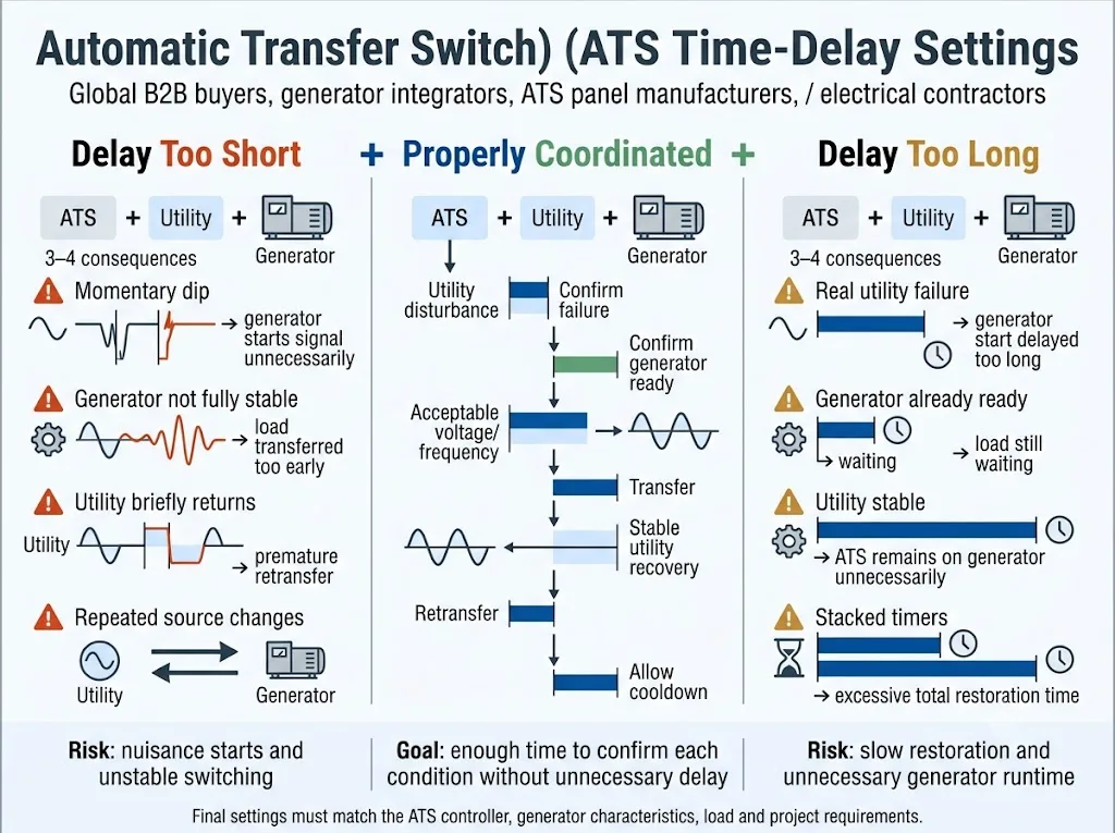
The examples below show why programmable-controller values cannot be treated as a universal ATS setting table.
| Function | Schneider TransferPacT Active Automatic | What This Means for a Compact ATS Buyer |
|---|---|---|
| Generator start | T7: 0–120 s; default 3 s | Confirm whether the selected system provides adjustable start timing or uses another controller |
| Transfer | T2: 0–1800 s; default 3 s | Do not assume the compact ATS offers the same programmable transfer range |
| Retransfer | T6: 0–3600 s; default 60 s | Specify adjustable return timing if the project requires it |
| Generator cooldown | T9: 0–3600 s; default 60 s | Confirm whether cooldown belongs to the generator controller or transfer-control system |
Source: Schneider Electric TransferPacT documentation [2]. These values describe a programmable controller platform and are included for comparison only.
Calculate the Complete Restoration Time, Not Just One ATS Number
A generator-backed system can take longer to restore power than the mechanical switching time of the ATS. The load experiences the complete source-failure and generator-start sequence.
Not every system implements these stages as separate timers. Some functions can overlap, be fixed, reset or be controlled by different devices. Confirm the installed architecture before calculating the final timing budget.
Check for Delay Stacking Between the ATS and Generator Controller
A compact ATS installation can still contain several controllers. The transfer switch may handle source transfer while the generator controller handles engine-start or shutdown logic.
If both systems intentionally delay the same event, the total response can become longer than expected. This is why commissioning should record real timestamps rather than only reading one timer value from one device.
If a start command is issued promptly but the engine begins later, investigate the generator-control sequence. If the start command itself is late, investigate the source-failure and ATS control logic.
ATS Delay Troubleshooting: Match the Symptom to the System Stage
| Observed Symptom | Check First |
|---|---|
| Generator starts during very short utility disturbances | Source sensing, failure-confirmation logic and which controller initiates the start sequence |
| Generator starts much later than expected | ATS logic, generator-controller timing and any external PLC or control delay |
| Generator is running but the load does not transfer | Alternate-source qualification, ATS transfer logic, permissive conditions and alarms |
| ATS returns to utility and then transfers away again | Utility stability, source sensing and the system's retransfer-confirmation logic |
| Utility is stable but the system remains on generator too long | Return mode, retransfer timing and which controller owns the return sequence |
| Generator stops immediately after retransfer | Generator-controller cooldown logic and any stop-delay function in the control system |
| Total restoration time is longer than expected | Timestamp the entire system sequence instead of inspecting only the ATS switching time |
How to Commission Timing in a Compact Generator ATS System
Do not begin by changing every available timer. First establish which device controls each event, then measure the actual sequence experienced by the load.
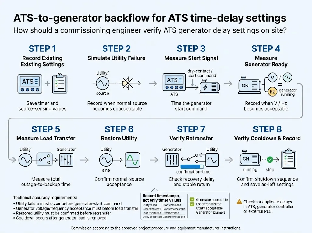
Loss-of-source and transfer testing must follow the site's approved electrical safety and commissioning procedure. The installed ATS instructions, generator instructions and project design govern the actual test method.
What Buyers Should Confirm for a LEEYEE Compact Generator ATS Project
For a compact ATS, do not copy a specification checklist intended for a large programmable transfer-switch controller. Start with the actual transfer requirement, then identify which timing functions the project needs.
Before Ordering or Model Confirmation
If the project requires independently adjustable start, transfer, retransfer or cooldown timers, send those requirements with the enquiry. Do not assume that every compact ATS includes the same programmable functions as the high-end controller examples used in this article.
Need to Confirm a Compact ATS for a Generator System?
Send your system voltage, rated current, 2P/4P requirement, generator information, load type and required operating sequence. LEEYEE can confirm the suitable compact ATS configuration and identify any timing or control requirements that need separate project verification.
FAQ: ATS Time Delay Settings for Compact Generator Systems
Does every compact ATS have adjustable generator start, transfer, retransfer and cooldown timers?
No. Timer availability depends on the ATS and system architecture. Some timing may be fixed in the ATS, some may be adjustable, and some may be handled by the generator controller or an external control system. Confirm the selected model before ordering.
What are typical ATS time delay settings for a generator?
There is no universal group of settings that should be copied into every project. Manufacturer documentation shows different timer structures, ranges and defaults between programmable ATS families.[2][4] The final sequence must match the installed equipment and project requirement.
Is ATS time delay the same as ATS transfer switching time?
No. Time delay is an intentional control waiting period. Transfer switching time is associated with the source-change operation after the control system permits transfer. Generator starting and source qualification can add significant time before switching occurs.
Should the ATS transfer as soon as the generator engine starts?
Not simply because the engine is running. The alternate electrical source must become acceptable for the intended system before the load is transferred.
Why is the generator running but the ATS has not transferred?
Check generator voltage/frequency condition, source qualification, ATS operating logic, external permissives and any active timing function. The delay may not be caused by the switching mechanism itself.
Who controls generator cooldown in a compact ATS system?
It depends on the system design. The generator controller often participates in the engine stop sequence, while some programmable ATS systems also provide cooldown timing. Confirm which device owns the stop logic for the project.
Why is the actual outage longer than the ATS switching time?
Because switching time is only one part of a generator backup sequence. Source-failure detection, intentional delays, generator crank time and source qualification can occur before the ATS changes source.
What information should I send LEEYEE before ordering a generator ATS?
Send the system voltage and frequency, rated current, required 2P/4P configuration, generator information, load type, required operating sequence and any specific timing or control requirements.
References
The programmable-controller values below are included as traceable industry examples. They must not be interpreted as specifications for the LEEYEE compact ATS unless confirmed for the selected model.
- IEC. IEC 60947-6-1:2026 — Low-voltage switchgear and controlgear — Part 6-1: Multiple function equipment — Transfer switching equipment. Edition 4.0, 2026. IEC official publication page .
- Schneider Electric. TransferPacT Active Automatic and Automatic User Guide — Time Delay. Document DOCA0214EN. Includes T2 Transfer Delay, T6 Re-Transfer Delay, T7 Genset Start Delay and T9 Genset Cool Delay. Schneider Electric official product documentation .
- Schneider Electric. TransferPacT Active Automatic and Automatic User Guide — Auto Mode. Utility-generator transfer and retransfer operating logic. Schneider Electric official auto-mode documentation .
- Cummins Inc. North America Product Line — Transfer Switches. 2025 product comparison. Includes controller-family information for transfer, retransfer, engine-start delay and engine-stop delay. Cummins official PDF .
- Schneider Electric / ASCO Power Technologies. How to conduct generator test with load transfer for a 165 Series ATS? FAQ000233188. Schneider Electric official FAQ .
