
Inhaltsübersicht
So wählen Sie einen 24-V-Signal-Überspannungsschutz
Eine 24V-Kennzeichnung allein reicht nicht aus, um einen Überspannungsschutz für einen Sensor- oder SPS-I/O-Stromkreis auszuwählen. Das richtige SPD muss außerdem zum Signaltyp, zur Schaltungstopologie, zur Leiteranzahl, zum Schleifenstrom, zum zulässigen Serienwiderstand, zum Schutzniveau und zur Einbauposition passen.
Verwenden Sie einen SPD für Signalleitungen – keinen allgemeinen 24V-DC-Leistungsschutz-SPD –, wenn ein externer Sensor, Transmitter, Schalter oder Aktor an einen PLC-I/O-Kanal angeschlossen ist. Wählen Sie den SPD entsprechend der DI-, DO-, AI- oder AO-Funktion aus. Bei analogen Schaltungen bestätigen Sie vor der Freigabe des Modells den Serienwiderstand, den Leckstrom, die Kapazität und die Schleifen-Spannungsreserve.
24V-Sensor- und PLC-I/O-Schaltungen, einschließlich digitaler Schaltung, 4–20mA, 0–10V, Leiteranordnung, Feldinstallation und Schutz am Schaltschrank-Eintritt.
Allgemeine 24V-DC-Leistungssammelschienen, 48V-Telekommunikationsversorgung, Solar-PV-DC-Schaltungen oder RS485-Protokollverdrahtung. Für diese Anwendungen gelten separate Auswahlregeln.
Schnellauswahlleitfaden für 24-V-Signal-SPDs
Beginnen Sie mit dem tatsächlichen Schaltkreis. Wählen Sie nicht allein anhand der Nennspannung aus.
Floating-Loop- oder Referenzanordnung, maximale Schleifenspannung, Schleifenstrom, niedriger Serienwiderstand, geringe Leckage und HART Kompatibilität, falls erforderlich.
Modellbestätigung erforderlich+24V, 0V, Schaltausgang, Sourcing- oder Sinking-Logik, Eingangs schwellwert, Leckstrom und Klemmenanordnung.
Verdrahtungsprüfung erforderlichAusgangstyp, Laststrom, Polarität, gemeinsamer Leiter und maximaler Dauerbetriebsstrom.
Überprüfung der Last erforderlichMaximale Signalspannung, Referenztopologie, Leckstrom, Serienwiderstand, Kapazität und zulässiger Signalfehler.
Modellbestätigung erforderlichSchnittstelle, Betriebsspannung, Aderzahl, Baudrate, Kapazität, Erdung und Schirmungskonzept.
Produktrichtung LY10DC-Versorgungsspannung, maximaler Laststrom, Polarität, Fehlerzustände und Anforderungen an den Überspannungsschutz (SPD) für den Leistungskreis.
Separate Auswahl des Überspannungsschutzes (SPD) für die StromversorgungGeben Sie den Schaltkreis als „Zweileiter 4–20mA AI“, „Dreileiter PNP DI“, „24V Transistor DO“ oder „0–10V AO“ an. Eine Anfrage, die lediglich „24V SPD“ enthält, bietet keine ausreichende Grundlage für eine zuverlässige Modellauswahl.
Wann benötigt eine 24-V-Sensor- oder PLC-I/O-Leitung ein SPD?
Nicht jede interne Steuerleitung erfordert einen individuellen Schutz. Die Entscheidung hängt von der Exposition der Kabel, den Installationsgrenzen, der Empfindlichkeit der Geräte und den betrieblichen Ausfallkosten ab.
Feldgerät für den Außenbereich
Sensoren und Messumformer, die im Außenbereich installiert sind, können auch ohne direkten Blitzeinschlag induzierte transiente Spannungen über ihre Feldverkabelung empfangen.
Lange Leitungswege
Lange Kabel bieten einen größeren Kopplungspfad für Blitzeinwirkungen, Schalthandlungen und Spannungsunterschiede zwischen verschiedenen Standorten.
Gebäudeübergreifende Verbindung
Die Verkabelung zwischen Gebäuden, in externen Anschlusskästen oder zwischen verschiedenen Potenzialausgleichszonen kann beide Enden des Stromkreises gefährden.
Hohe Ausfallkosten
Verfahrenstechnische Anlagen, Wassersysteme, Pumpstationen und automatisierte Fertigungslinien können einen lokalen Schutz rechtfertigen, da eine einzelne defekte E/A-Karte ein größeres System zum Stillstand bringen kann.
Der Schaltkreis arbeitet zwar möglicherweise nur mit 24 V, doch eine in das Kabel eingekoppelte Transiente kann die Belastbarkeit des SPS-Eingangs, des Messumformers oder der Sensorschnittstelle übersteigen. Die Prüfung der Stoßspannungsfestigkeit und die Leistung von Signal-SPDs werden daher unabhängig von der normalen Betriebsspannung bewertet. [1][3]
24-V-DC-Leistungs-SPD vs. 24-V-Signal-SPD
Beide Produkte enthalten möglicherweise „24V“ in ihrer Beschreibung, sie schützen jedoch unterschiedliche Stromkreise und können nicht anhand derselben Parameter ausgewählt werden.
| Auswahlpunkt | 24V DC-Überspannungsschutz | 24V Signal-Überspannungsschutz |
|---|---|---|
| Hauptzweck | Schutz einer Gleichstromversorgung, eines Hilfsstromkreises oder eines Geräteeingangs. | Schutz von SPS-E/A, Sensoren, Messumformern oder Niederspannungs-Steuerleitungen. |
| Nennstrom | Muss möglicherweise den Dauerstrom einer vollständigen Last tragen. | Führt üblicherweise einen geringeren Signal- oder Schleifenstrom und muss das Signalverhalten beibehalten. |
| Wichtige Parameter | Uc, Laststrom, Polarität, Schutzpegel, Fehlerbedingungen und Netztopologie. | Uc, Begrenzungsspannung, Leckstrom, Serienwiderstand, Kapazität, Bandbreite und Schaltungstopologie. |
| Typische Schaltung | SPS-Stromeingang, 24V-Hilfsbus oder Stromversorgung für Industriesteuerungen. | DI, DO, 4–20mA, 0–10V sowie Sensor- oder Transmitterverdrahtung. |
| Hauptrisiko bei der Auswahl | Ein SPD für die Stromversorgung bietet möglicherweise nicht die erforderlichen Signaleigenschaften für einen analogen oder digitalen E/A-Schaltkreis. | Ein Signal-SPD ist unter Umständen nicht für die Stromaufnahme einer 24-V-DC-Last ausgelegt. |
| Relevante Anwendungsnorm | Überprüfen Sie die für den spezifischen DC-Stromkreis geltenden Normen und Prüfdokumentationen. | IEC 61643-21 gilt für Überspannungsschutzgeräte (SPDs), die an Telekommunikations- und Signalnetzwerke angeschlossen sind.[1] |
PV-DC-SPDs, DC-Stromversorgungs-SPDs für die Telekommunikation, Hilfsstromversorgungs-SPDs und Signalleitungs-SPDs können alle in Gleichstromkreisen betrieben werden, jedoch unterscheiden sich ihre Spannungen, Strompfade, Prüfanforderungen und Anwendungsbereiche.
Wie DI, DO, AI und AO die Auswahl des Signal-SPD beeinflussen
Die E/A-Funktion gibt dem Lieferanten an, was der Stromkreis überträgt und was während des Normalbetriebs erhalten bleiben muss.
| SPS-Funktion | Typischer Schaltkreis | Parameter zur Bestätigung | Auswahlwarnung |
|---|---|---|---|
| DI Digitaleingang | PNP- oder NPN-Näherungsschalter, Endschalter, Druckschalter oder potenzialfreier Fernkontakt. | Maximale Nennspannung, gemeinsames Bezugspotenzial, PNP/NPN-Logik, geschützte Leiter, Leckstrom und Eingangsschwellenwert. | Übermäßiger Leckstrom kann den Zustand eines empfindlichen Eingangs beeinträchtigen. Weisen Sie keine Klemmen zu, bevor Sie die Sourcing- oder Sinking-Logik bestätigt haben. |
| DO Digitaler Ausgang | Transistor- oder Relaisausgang zur Steuerung eines Ventils, Relais, einer Lampe oder eines Aktuators. | Ausgangstyp, maximaler Laststrom, Polarität, gemeinsamer Leiter und Lasteigenschaften. | Ein Signal-Überspannungsschutzgerät ersetzt keine Freilaufdiode oder andere lokale Unterdrückungsmaßnahmen, die für wiederkehrende induktive Schaltvorgänge erforderlich sind. |
| AI Analogeingang | 4–20 mA Druck-, Füllstands- oder Durchflussmessumformer; 0–10 V Sensorausgang. | Schleifenspannung, Strom, Serienwiderstand, Leckstrom, Begrenzungsspannung, Kapazität und bei Bedarf HART-Kompatibilität. | Zusätzlicher Widerstand oder Leckstrom kann die Schleifenspannungsreserve verringern oder Messfehler verursachen. |
| AO Analogausgang | SPS-Ausgang an einen Ventilstellungsregler, Antriebsreferenzwert, Aktor oder Fernsteuergerät. | Ausgangsbereich, maximale Bürde, Ausgangsstrom, zusätzliche Impedanz und zulässiger Signalfehler. | Stellen Sie sicher, dass der Ausgang den vollständigen Stromkreis auch nach Einbeziehung des Überspannungsschutzes (SPD) und des Leitungswiderstands noch ansteuern kann. |
Zwei-, Drei- und Vierleitersensoren benötigen unterschiedliche Schutzpfade
Die Leiteranordnung bestimmt, ob sich Stromversorgung und Signal dasselbe Adernpaar teilen und wie viele externe Leiter geschützt werden müssen.
Zweileiter-Messumformer
Ein 4–20-mA-Zweileiter-Messumformer nutzt üblicherweise dasselbe Adernpaar sowohl für die Betriebsspannung als auch für den Messstrom.
- Bestätigen Sie die maximale Schleifenspannung, nicht nur die Nennspannung von 24 V.
- Bestätigen Sie den zusätzlichen Serienwiderstand und die Schleifenstromkapazität.
- Bestätigen Sie die HART-Kompatibilität, sofern Kommunikation verwendet wird.
Drei-Leiter-Sensor
Ein herkömmlicher Drei-Leiter-Sensor verfügt über +24V, 0V und einen separaten digitalen oder analogen Ausgang, der sich die Versorgungsreferenz teilt.
- Bestätigen Sie den PNP-, NPN-, Sourcing- oder Sinking-Betrieb.
- Identifizieren Sie jeden Leiter, der die Schutzzone verlässt.
- Gehen Sie nicht davon aus, dass ein Zweidraht-Schleifen-ÜSS ausreichend ist.
Vierdraht-Instrument
Stromversorgung und Signal können über separate Adernpaare geführt werden, was getrennte Schutzfunktionen oder eine koordinierte Mehrleiterlösung erfordert.
- Getrennte Anforderungen für Strom- und Signalpaare.
- Bestätigen Sie, ob das Signalpaar potenzialfrei oder bezogen ist.
- Überprüfen Sie vor der Bestellung die Anzahl der Anschlüsse und die Schutzmodi.
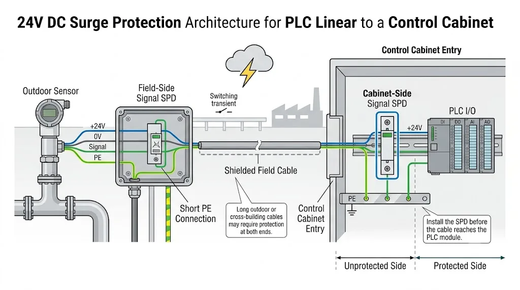
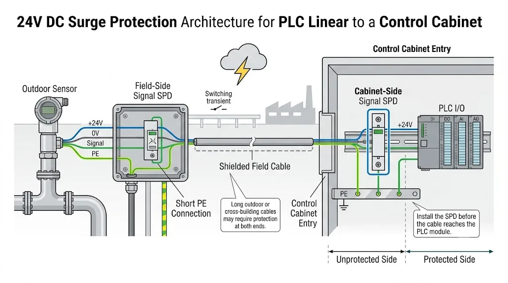
SPD am Feldende, Schaltschrankende oder an beiden Enden installieren?
Die Einbauposition richtet sich nach der Leitungsführung, der Schutzzonengrenze, dem Wert der Ausrüstung sowie den örtlichen Erdungsbedingungen.
| Installationsszenario | Typische Entscheidung zum Schutz | Technischer Grund |
|---|---|---|
| Kurze Verdrahtung innerhalb eines Schaltschranks | Ein dedizierter Signal-Überspannungsschutz ist häufig nicht erforderlich, sofern kein spezifisches internes Transientenrisiko identifiziert wurde. | Die Leiter überschreiten keine externe Schutzzone oder eine separate Erdungszone. |
| Innenraumgerät in derselben Potenzialausgleichszone | Ziehen Sie einen Schutz am Schaltschrankeingang in Betracht, wenn das Kabel lang, exponiert oder betriebskritisch ist. | Das SPS-Modul ist häufig der empfindlichere und kostspieligere Endpunkt. |
| Außensensor oder Messumformer | Ziehen Sie koordinierte Überspannungsschutzgeräte (SPDs) in der Nähe des Feldgeräts und am Schaltschrankeingang in Betracht. | Beide Endpunkte können entlang des Feldkabels transienten Spannungen ausgesetzt sein. |
| Kabel zwischen getrennten Gebäuden | Schützen Sie beide lokalen Endpunkte und überprüfen Sie die Erdung sowie die Schirmbehandlung. | Zwischen den beiden Erdungssystemen des Gebäudes können Potenzialunterschiede auftreten. |
| Messkreis für explosionsgefährdete Bereiche | Verwenden Sie einen entsprechend zugelassenen Überspannungsschutz (SPD), der auf das Design der Eigensicherheit abgestimmt ist. | Ein allgemeiner Signal-Überspannungsschutz darf nicht als für einen Ex-i-Stromkreis geeignet angesehen werden. |
Platzieren Sie den Überspannungsschutz (SPD) dort, wo das externe Feldkabel in den Schaltschrank eintritt, bevor das ungeschützte Kabel durch den SPS-Bereich geführt wird. Halten Sie die ankommenden Feldleiter von der geschützten Verkabelung getrennt, die vom SPD abgeht. Die IEC 61643-22 behandelt die Auswahl-, Platzierungs- und Koordinationsprinzipien für SPDs in Signalnetzwerken.[2]
Erdung und Schirmbehandlung für ein 24-V-Signal-SPD
Ein geeignetes Produkt kann trotz korrekter Wahl einen mangelhaften Schutz bieten, wenn der Ableitpfad zu lang ist oder wenn geschützte und ungeschützte Leitungen gemeinsam verlegt werden.
Schließen Sie den SPD auf dem kürzesten praktischen Weg an den PE des Schaltschranks oder an die Potenzialausgleichsstruktur an.
Wenn der SPD die Tragschiene als Teil seiner PE-Verbindung nutzt, muss die Schiene zuverlässig mit der PE-Struktur des Schaltschranks verbunden sein.
Führen Sie die eingehende Feldverdrahtung nach dem SPD nicht neben den geschützten Leitern entlang.
Die Kabelabschirmung dient der EMV und sollte nicht als Ersatz für den Erdungsanschluss des SPD verwendet werden.
Potentialfreie analoge Paare und digital geschaltete Stromkreise mit gemeinsamer Referenz können unterschiedliche Schutzmaßnahmen erfordern.
Die einseitige oder mehrpunktige Schirmerdung hängt vom EMV-Design und den Potenzialausgleichsbedingungen ab und folgt keiner universellen Regel.
Vor der Auswahl des SPD zu bestätigende Parameter
Diese Parameter bestimmen, ob der Schutzschalter den Normalbetrieb übersteht und den Anschluss schützt, ohne das Signal zu verzerren.
Geben Sie die Nennspannung und den höchsten zu erwartenden Wert an, einschließlich der Toleranz der Stromversorgung.
Identifizieren Sie DI, DO, AI, AO, 4–20 mA, 0–10 V, PNP, NPN oder eine andere definierte Schnittstelle.
Bestätigen Sie das erdfreie Paar, die gemeinsame Referenz sowie die erforderlichen Schutzmodi zwischen den Leitungen und gegen Erde.
Der Überspannungsschutz muss den Schleifen- oder Laststrom ohne übermäßige Erwärmung oder Spannungsabfall führen können.
Beziehen Sie den SPD-Widerstand in die Berechnung der gesamten Analogschleifenlast und der Spannungsreserve ein.
Ein übermäßiger Leckstrom kann den Eingangsschwellenwert einer SPS beeinflussen oder Fehler in empfindlichen analogen Schaltkreisen verursachen.
Vergleichen Sie die Begrenzungsspannung des SPD mit der Spannungsfestigkeit der SPS oder des Feldgeräts.
Stellen Sie sicher, dass der SPD das erforderliche Signal oder die überlagerte Kommunikation nicht abschwächt oder verzerrt.
Bestätigen Sie die Zwei-, Drei- oder Vierleiter-Konstruktion sowie die gemeinsamen Anschlüsse und Kanäle pro Modul.
Überprüfen Sie Betriebstemperatur, Montage, Gehäuse, Ex-Schutz-Status sowie die erforderliche Dokumentation der Normen.
Ein höherer Ableitstromwert macht ein Produkt nicht automatisch besser für einen SPS- oder Sensoranschluss. Auch die Testwellenform, der Schutzmodus, die Begrenzungsspannung und die Signaleigenschaften müssen berücksichtigt werden.
Praktische Auswahlbeispiele für 24-V-Sensor- und PLC-I/O-Anwendungen
Diese Beispiele verdeutlichen, warum Stromkreise mit einer Nennspannung von 24 V unterschiedliche Überspannungsschutzgeräte (SPDs) erfordern können.
Zweidraht-Messumformer für den Außenbereich, 4–20 mA
- Schützen Sie das vollständige Stromschleifenpaar.
- Überprüfen Sie die höchste Schleifenspannung und den maximalen Schleifenstrom.
- Addieren Sie den SPD-Widerstand zu den Berechnungen der Kabel- und SPS-Eingangslast.
- Stellen Sie bei Bedarf die HART-Kompatibilität sicher.
- Berücksichtigen Sie einen koordinierten Schutz an beiden Enden eines freiliegenden Kabels.
Drahtgebundener PNP-Sensor an SPS-Digitaleingang angeschlossen
- Identifizieren Sie +24V, 0V und den Schaltausgangsleiter.
- Bestätigen Sie die Schutzanordnung mit gemeinsamem Bezugspotenzial.
- Überprüfen Sie den Leckstrom anhand des PLC-Eingangsschwellenwerts.
- Sichern Sie die erforderlichen externen Leiter ab.
- Installieren Sie den SPD am Kabeleingang des Schaltschranks.
SPS-Digitalausgang zur Steuerung eines externen Magnetventils
- Ausgangstyp, Polarität und Laststrom bestätigen.
- Das lange externe Kabel am Schaltschrankübergang schützen.
- Geeignete lokale Entstörung für die Induktionsspule vorsehen.
- Erwarten Sie nicht, dass der Überspannungsschutz (SPD) die Unterdrückung bei wiederholten Schaltvorgängen ersetzt.
0–10V-Sensor an SPS-Analogeingang angeschlossen
- Maximale Signalspannung und Referenztopologie bestätigen.
- Priorisieren Sie geringe Leckströme und minimale zusätzliche Signalfehler.
- Überprüfen Sie den Serienwiderstand und die Kapazität.
- Geschützte und ungeschützte Leitungen getrennt verlegen.
- Verwenden Sie keinen allgemeinen 24V-Überspannungsschutz (SPD) als Ersatz.
Wo LY10 passt – und wo eine separate Bestätigung erforderlich ist
Der LEEYEE LY10 wird offiziell als Überspannungsschutz für Datensignale auf DIN-Schienen für RS485-, Telemetrie-, Fernwirk-, SPS-, Sensor- und industrielle Kommunikationsleitungen angeboten. Das verfügbare Sortiment umfasst Versionen für 12V-, 24V- und 48V-Signalsysteme.
Dies belegt nicht automatisch, dass eine bestimmte LY10-Version für jeden 4–20mA-, 0–10V-, AI-, AO- oder Drei-Draht-Sensorkreis geeignet ist. Die Kompatibilität muss anhand der vollständigen elektrischen Parameter des jeweiligen Stromkreises überprüft werden.
Offiziell bestätigte Produktausrichtung
- RS485- und industrielle Kommunikationsleitungen
- Telemetrie- und Fernwirksignale
- Signal-Systemvarianten für 12V, 24V und 48V
- Reiheneinbau auf DIN-Hutschiene
- Nennlaststrom mit 500mA angegeben
- Übertragungsrate bis zu 10 Mbit/s angegeben
- Einfügedämpfung mit maximal 0,2 dB angegeben
Anwendungen, die eine zusätzliche Bestätigung erfordern
- Zweidraht-4–20-mA-Messumformerschleifen
- 0–10V Analogeingänge und -ausgänge
- HART-fähige Analogschleifen
- Drei-Draht-PNP- oder NPN-Sensoren
- SPS-Ausgänge mit externer Laststromführung
- Stromkreise mit strengen Widerstands- oder Leckstromgrenzwerten
- Explosionsgefährdete oder eigensichere Schleifen
Häufige Fehler bei Auswahl und Installation
Ein 24V-Überspannungsschutz ist nicht automatisch für analoge oder digitale SPS-Signalstromkreise geeignet.
DI, DO, AI und AO können unterschiedliche Anforderungen an Strom, Referenz und Signalintegrität haben.
Falsche Annahmen bezüglich Sourcing, Sinking und dem gemeinsamen Leiter können zu einer fehlerhaften Anschlussbelegung führen.
Ein zusätzlicher Widerstand kann die verfügbare Schleifenspannung verringern oder die Messgenauigkeit beeinträchtigen.
Ungeschützte Feldverdrahtung sollte nicht durch den empfindlichen SPS-Bereich geführt werden, bevor sie den SPD erreicht.
Die Wellenform, der Schutzmodus, die Begrenzungsspannung sowie die Signalparameter sind für einen aussagekräftigen Vergleich ebenfalls erforderlich.
Was ein OEM-Einkäufer oder Schaltschrankbauer bestätigen sollte
Stellen Sie ausreichende Schaltkreisinformationen bereit, um Fehler bei Modell, Anschluss, Beschriftung und Abtastung zu vermeiden.
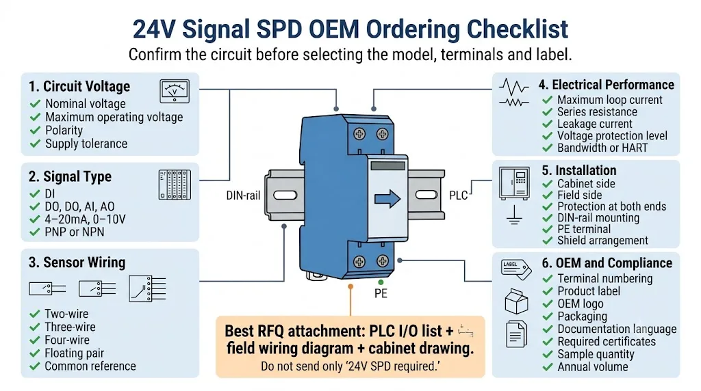
Liste zur technischen und kommerziellen Bestätigung
- Nenn- und maximale Schaltkreisspannung
- DI-, DO-, AI- oder AO-Funktion
- 4–20 mA, 0–10 V, PNP, NPN oder Datensignal
- Zwei-, Drei- oder Vierleiter-Schaltung
- Potentialfreie oder massebezogene Topologie
- Maximaler Schleifen- oder Laststrom
- Zulässiger Widerstand, Leckstrom und Signalfehler
- Leiter, Kanäle und Klemmennummerierung
- Hutschienen-, Schaltschrank- oder Feldmontage
- Temperatur-, Ex-Bereichs- und Zulassungsanforderungen
- Anforderungen an OEM-Logo, Etikettierung und Verpackung
- Musterstückzahl und geschätztes Jahresvolumen
FAQ zum 24V Signal Surge Protector
Braucht jeder 24V-Sensor einen Überspannungsschutz?
Nein. Bei kurzer Verkabelung, die sich vollständig innerhalb eines Schaltschranks befindet, ist unter Umständen kein separater Signal-ÜSS erforderlich. Der Schutz gewinnt bei Außengeräten, langen Kabelwegen, gebäudeübergreifender Verkabelung, getrennten Erdungszonen sowie Systemen mit hohen Ausfallkosten an Bedeutung.
Kann ein 24V SPD DI, DO, AI und AO schützen?
Nicht automatisch. Digitale und analoge Schaltkreise können unterschiedliche Anforderungen an Topologie, Stromstärke, Leckstrom, Widerstand, Kapazität und Signalintegrität aufweisen. Überprüfen Sie die genaue E/A-Funktion, bevor Sie das Modell auswählen.
Kann ein 24V-DC-Überspannungsschutzgerät eine 4–20mA-Schleife schützen?
Dies sollte nicht vorausgesetzt werden. Ein 4–20mA-Stromkreis erfordert einen Signalschutz, der auf die Schleifenspannung, den Strom, den Widerstand, den Leckstrom, die Begrenzungsspannung und die Kommunikationsanforderungen abgestimmt ist.
Beeinflusst ein Überspannungsschutzgerät (SPD) eine 4–20-mA-Messung?
Dies kann der Fall sein, wenn dessen Serienwiderstand oder Leckstrom ungeeignet ist. Berücksichtigen Sie den SPD-Widerstand bei der Berechnung der Bürde für Transmitter, Kabel und SPS-Eingang und stellen Sie sicher, dass ein ausreichender Schleifenspannungsspielraum verbleibt.
Wo sollte das SPD in einem PLC-Gehäuse installiert werden?
Installieren Sie das Gerät an der externen Kabeleinführung, bevor die Feldverkabelung die SPS-E/A-Klemmen erreicht. Halten Sie die PE-Verbindung kurz und trennen Sie die eingehende Feldverkabelung von der geschützten Seite.
Ist der LY10 für jeden 24V PLC I/O-Kreis geeignet?
Es sollte keine universelle Eignung vorausgesetzt werden. Das LY10 ist offiziell für RS485 und kompatible industrielle Kommunikationsleitungen spezifiziert. Für 4–20-mA-, 0–10-V-, AI-, AO-, PNP- oder NPN-Schaltkreise ist eine Überprüfung anhand der tatsächlichen elektrischen Parameter erforderlich.
Jedes Schutzthema getrennt behandeln
Verwenden Sie diese Seite für 24V-Sensor- und SPS-E/A-Signale. Nutzen Sie die entsprechenden Anleitungen für die vollständige Architektur des Schaltschranks sowie die RS485-Kommunikationsverdrahtung.
Technische Referenzen
- IEC 61643-21:2025, Überspannungsschutzgeräte für den Einsatz in Telekommunikations- und signalverarbeitenden Netzwerken – Anforderungen und Prüfverfahren. IEC-Publikationsseite .
- IEC 61643-22:2015, Auswahl, Betrieb, Anordnung und Koordinationsprinzipien für Überspannungsschutzgeräte in Telekommunikations- und signalverarbeitenden Netzwerken. IEC-Publikationsseite .
- IEC 61000-4-5:2014+A1:2017, Elektromagnetische Verträglichkeit (EMV) – Prüfung der Störfestigkeit gegen Stoßspannungen. IEC-Publikationsseite .
- Phoenix Contact, Überspannungsschutz für Mess-, Steuer- und Regelungstechnik, einschließlich analoger und massebezogener Signalstromkreise. Technische Seite von Phoenix Contact .
- Weidmüller, Überspannungsschutz für Mess-, Steuer- und Regelkreise, einschließlich analoger und binärer Signale. Technische Seite von Weidmüller .
- Produktinformationen zum LEEYEE LY10 Hutschienen-Überspannungsschutz für Datensignale. LEEYEE Produktseite .
Benötigen Sie einen 24V Signal SPD für einen echten PLC I/O-Stromkreis?
Bitte senden Sie die SPS-E/A-Liste, die Sensorverdrahtung, die maximale Schaltkreisspannung, den Schleifen- oder Laststrom, die Kabellänge sowie die Erdungskonfiguration. LEEYEE wird zunächst die Anforderungen für Stromversorgung, digitale E/A, Analogschleifen und Kommunikation trennen, bevor ein Modell bestätigt wird.
