
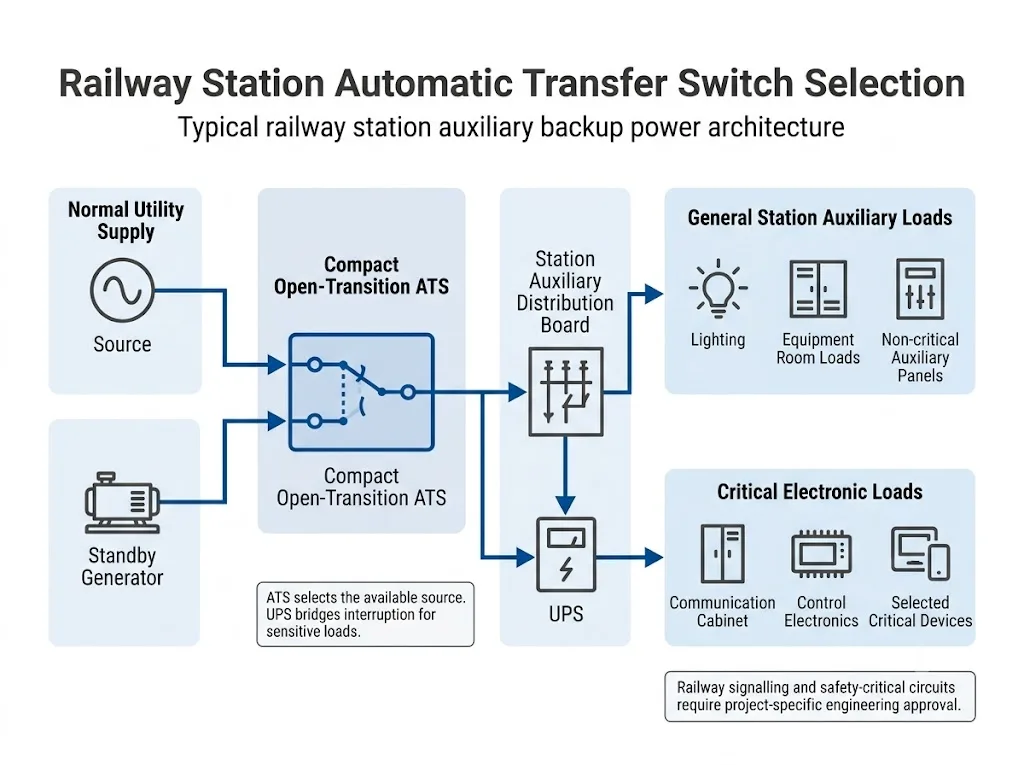
Railway station auxiliary power systems often need an automatic way to move selected low-voltage loads from a normal source to a standby source. A compact automatic transfer switch can perform this source-transfer function for suitable station auxiliary feeders, but ATS selection must start with the load, the permitted interruption and the railway project requirements—not with current rating alone.
Inhaltsübersicht
Quick Answer: When Can a Railway Station Use an Automatic Transfer Switch?
An automatic transfer switch can be used in a railway station auxiliary power system to transfer an identified low-voltage load between two power sources, such as utility power and a standby generator. IEC 60947-6-1:2026 defines transfer switching equipment for transferring loads between power-supply sources and covers automatic transfer switching equipment. [1]
For ordinary station auxiliary loads, a compact open-transition ATS may be considered when its voltage, current, pole arrangement, switching duty, short-circuit coordination and control functions match the feeder.
Railway signalling, interlocking, train-control and other safety-critical systems require separate engineering confirmation. These systems may use redundant supplies, UPS equipment, static transfer equipment or other railway-specific arrangements rather than relying on a conventional ATS alone. [2][3]
Start With Station Auxiliary Power, Not With a “Railway ATS” Label
A railway station contains many different electrical loads. General lighting, equipment-room feeders, communication cabinets, station services and signalling equipment do not necessarily require the same level of continuity.
This is why the most useful selection question is:
What does this feeder supply, and how long can that load tolerate loss of power?
The final column is the key procurement question: it explains what must be confirmed before a compact ATS can be considered suitable.
| Station Load | Power Requirement | Selection Meaning |
|---|---|---|
| General station lighting | Restore power after normal-source failure | A conventional LV ATS may be considered if the permitted interruption and project requirements allow it. |
| Equipment-room auxiliary loads | Continue operation from an alternate source | Confirm current, inrush where relevant, source arrangement and protective coordination. |
| Communication equipment feeder | May require higher continuity | Determine whether ATS transfer interruption is acceptable or whether UPS support is also required. |
| Station monitoring or control equipment | Interruption tolerance depends on connected equipment | Check the equipment specification before defining the backup architecture. |
| Signalling or interlocking circuits | High availability and railway-specific safety requirements | Do not approve a normal compact ATS without the required railway engineering and system approval. |
Bedeutung für Käufer: the same railway station can use different backup-power solutions for different load groups. “Railway application” alone is not a valid ATS specification.
Engineering Boundary: LEEYEE Does Not Present a Standard Compact ATS as a Railway Signalling Safety Device
A standard low-voltage ATS can perform source transfer, but railway signalling and train-control systems may be governed by dedicated safety, availability, redundancy, environmental and equipment-approval requirements.
LEEYEE compact ATS products should therefore be evaluated for a defined low-voltage application. Suitability for signalling, interlocking, train control or another safety-related railway circuit must be confirmed against the actual railway authority and system-integrator requirements.
Real Railway Engineering Uses ATS and UPS for Different Jobs
Real railway power design supports an important distinction: an ATS selects the power source, while a UPS supports loads that require continuity during the interruption between sources.
Railway Station Engineering Example
A 2025 RITES railway station engineering document specifies standby generator supply through an automatic transfer switch to designated low-voltage emergency distribution. The same project documentation separates loads requiring continuous UPS-supported power, including telecommunications and other critical station systems. [2]
This reflects the same design logic a railway ATS buyer should use: ATS-supported emergency distribution and UPS-supported continuous loads are not automatically the same load group.
Transport for NSW railway documentation also provides a documented example in which two incoming supplies feed an automatic transfer switch ahead of an essential-services board and UPS. The document discusses UPS or static switching where critical supply points require seamless changeover. [3]
ATS vs UPS in Railway Station Backup Power
An ATS and a UPS are complementary devices. A transfer switch changes which source feeds the load. A UPS can supply stored-energy ride-through to compatible downstream equipment when the normal source is lost.
In a utility-to-generator system, the total outage experienced by the load may include source-failure detection, generator starting, generator stabilisation, any programmed delay and the transfer operation itself. A mechanical ATS does not provide stored energy during that interval.
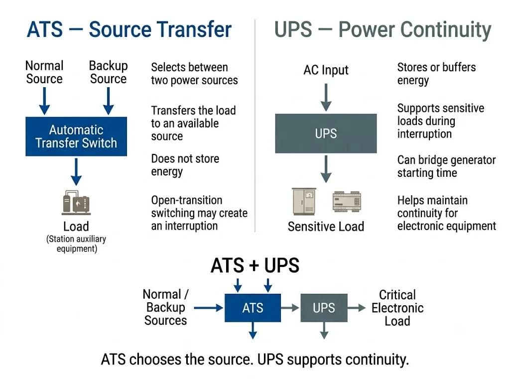
This table compares functions, not model-specific performance. Final design values must come from the selected equipment documentation.
| Funktion | ATS | UPS |
|---|---|---|
| Select between two power sources | Hauptfunktion | Not the normal primary role |
| Provide stored-energy ride-through | Nein | Yes, when correctly selected and sized |
| Bridge generator starting time | No stored-energy supply | Can support the load if sufficient autonomy is designed |
| Open-transition interruption | Normally present for open-transition ATS | Can support compatible loads through the interruption |
| Main project purpose | Source selection | Power continuity for supported loads |
Einkaufsfazit: for sensitive railway electronics, the correct architecture may be ATS plus UPS rather than ATS instead of UPS.
Why Open-Transition ATS Selection Starts With Interruption Tolerance
LEEYEE's standard compact ATS scope discussed on this page is based on ordinary open-transition source transfer. Open transition is a break-before-make sequence: the first source is disconnected before the alternate source is connected.
IEC 60947-6-1:2026 separately addresses automatic transfer switching equipment and includes specific provisions for ATSE with closed-transition capability. This confirms that transition behaviour is an equipment characteristic that must be identified rather than assumed. [1]
A brief interruption may be acceptable for some station auxiliary loads. It may be unacceptable for processor-based control, communication or safety-related equipment.
How Utility-to-Generator ATS Operation Works
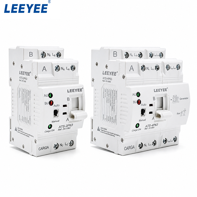
The real LEEYEE product shown above is well aligned with this type of application because it is a compact dual-source ATS format with Auto / Manual control and a generator-related marking visible on the 4-pole unit. However, the exact generator-start logic and terminal functions must still be confirmed from the selected model documentation.
A typical station auxiliary generator-backup sequence can be understood in five stages.
- Normal supply available: the auxiliary load is connected to the preferred source.
- Normal source becomes unacceptable: the controller detects the source condition according to its configured logic.
- Generator starts: the standby generator starts and reaches an acceptable operating condition.
- Load transfers: the ATS connects the selected station auxiliary feeder to the alternate source.
- Normal supply returns: after the preferred source satisfies the configured return conditions, the system can retransfer according to the approved sequence.
The actual voltage thresholds, frequency thresholds, generator-start contacts, time delays and retransfer logic depend on the ATS controller and project design. They must be verified from the model-specific documentation.
How to Select an ATS for Railway Station Auxiliary Power
The most reliable selection method follows the real engineering decision path rather than starting with an ATS model number.
Define the exact station load
Identify whether the feeder supplies lighting, an equipment room, auxiliary machinery, a communication cabinet, general control equipment or a safety-related railway function.
Identify both power sources
Confirm whether the arrangement is utility-to-generator, utility-to-utility or another approved two-source configuration.
Confirm voltage, frequency and phase
Provide the actual operating voltage, frequency and whether the feeder is single-phase or three-phase. Current rating alone is not enough to select a transfer switch.
Confirm the designed current
Evaluate continuous load and any relevant starting or inrush characteristics together with the upstream protective system.
Confirm the required pole configuration
The real LEEYEE compact ATS image on this page shows 2-pole and 4-pole configurations. Pole selection must follow the system phase arrangement, neutral treatment, earthing design, source configuration and project requirements. Do not assume that every three-phase project requires the same neutral-switching arrangement.
Define the maximum permitted interruption
If the connected load cannot tolerate open-transition interruption or generator starting time, an ATS alone may not provide the required continuity.
Check short-circuit coordination
Confirm prospective short-circuit conditions, upstream protection and the documented short-circuit performance of the exact ATS configuration. Rated current alone does not establish suitability at the installation point.
Confirm remote status requirements
Determine which source-availability, switch-position, alarm and operating-mode signals must be provided to the local panel, SCADA, BMS or other supervisory system.
Check the current railway project documents
Confirm the operator's current electrical specification, environmental requirements, EMC requirements, documentation requirements and equipment-approval process before model approval.
Which Remote Status Signals May Matter?
Railway station maintenance and supervisory systems often need operating information from the transfer system. Depending on the selected ATS and project interface, the buyer may need to confirm signals such as:
- Normale Quelle verfügbar
- Emergency or alternate source available
- Load connected to normal source
- Load connected to emergency source
- Auto / Manual operating status
- Fault alarm
The real product image confirms front-panel Auto / Manual operation and visible status indication, but it does not by itself prove that every model provides all of the remote outputs listed above. Exact dry contacts, terminals, communication interfaces and protocol capability must be checked on the selected LEEYEE model.
Where This Compact LEEYEE ATS Is More Appropriate
More Suitable for Evaluation
- Station auxiliary distribution feeders
- Selected emergency lighting circuits
- Equipment-room low-voltage loads
- General station auxiliary panels
- Generator-backed auxiliary feeders
- Communication-support feeders where interruption tolerance is known
- OEM equipment requiring ordinary dual-source LV transfer
Requires Additional Engineering Review
- Railway signalling safety circuits
- Interlocking systems
- Train-control systems
- Loads requiring seamless transfer
- Applications outside documented ATS ratings
- Projects requiring railway-specific product approval
This boundary keeps the page aligned with the real product scope: LEEYEE's compact ATS is discussed here as a low-voltage backup source-transfer device, not as a universal railway signalling power solution.
What IEC 60947-6-1:2026 Tells the Buyer
IEC 60947-6-1:2026 applies to transfer switching equipment used to transfer loads between power-supply sources at rated voltages not exceeding 1,000 V AC or 1,500 V DC. It covers manually operated, remotely operated and automatic transfer switching equipment, including ATSE controllers. [1]
The 2026 edition also contains specific provisions for bypass/isolation transfer switching equipment, ATSE with closed-transition capability and stand-alone ATS controllers. [1]
However, an IEC transfer-switch product standard is not the same thing as railway system approval. A railway or metro project may impose additional requirements for safety, environment, EMC, fire performance, documentation, communication and approved equipment.
Certification and Project Approval Must Be Checked Separately
Reference to IEC 60947-6-1 in this article does not mean that every LEEYEE ATS model is certified to every edition of the standard or automatically approved for a railway project.
Before approval, request the exact model datasheet and applicable certificate or test documentation, then compare their scope with the current railway project specification.
Why Current Railway Project Documents Matter
Railway electrical standards change over time. Older official railway documents can remain useful as engineering examples, but they should not automatically be treated as the current requirement for a new project.
Transport for NSW, for example, maintains a current standards system for railway infrastructure, including low-voltage electrical installation requirements. Project teams should therefore confirm the current applicable document rather than copying the standard reference from an older railway design. [4]
What Can Go Wrong if ATS Selection Is Based Only on Current Rating?
Railway station auxiliary ATS errors often come from missing a system requirement rather than misunderstanding the basic definition of an ATS.
| Selection Error | Possible Consequence |
|---|---|
| Using ATS-only backup for a load that cannot tolerate interruption | Electronic equipment may reset or lose operation while the alternate source becomes available. |
| Choosing only by ampere rating | The switch may not match the voltage, phase, pole configuration, source arrangement or operating duty. |
| Assuming every three-phase feeder uses the same neutral arrangement | The selected switching configuration can conflict with the system earthing or source design. |
| Ignoring short-circuit conditions | The selected ATS and upstream protection may not be correctly coordinated for the installation point. |
| Treating IEC compliance as railway approval | The device may still fail the railway project's technical approval process. |
| Not defining monitoring requirements | Required source, switch-position or alarm signals may be unavailable to the station supervisory system. |
Ingenieurtechnische Schlussfolgerung: define the railway station feeder and acceptance criteria first; select the ATS model second.
Before Ordering a Railway Station Auxiliary ATS
Send the following information so the transfer application can be reviewed against the actual project:
- Project: country, railway or metro operator and current project specification
- Last: exact equipment supplied by the feeder
- Criticality: whether the load is ordinary auxiliary equipment or safety-related
- Normal source: utility or other incoming supply
- Alternate source: generator, second incoming supply or other approved source
- Spannung: actual system operating voltage
- Frequency: operating frequency
- Phase: single-phase or three-phase
- Current: designed feeder current and relevant inrush information
- Pole: required pole configuration; the real LEEYEE product shown here includes 2P and 4P versions
- Continuity: maximum permitted interruption
- Generator interface: required generator-start and status functions
- Schutz: upstream protective device and available short-circuit information
- Überwachung: required dry contacts, alarms or communication interface
- Dokumentation: required standard, certificate, drawing or datasheet
- Einbau: cabinet space, mounting arrangement and environmental conditions
- Commercial: quantity and any OEM or private-label requirement
Need to Review a Railway Station Auxiliary ATS Configuration?
Send LEEYEE the station load, two power sources, system voltage, current, required pole configuration, permitted interruption, upstream protection and railway project specification. We can review whether the compact ATS configuration matches the stated low-voltage application and identify items that still require project-engineer confirmation.
Häufig gestellte Fragen
Can an automatic transfer switch be used in a railway station?
Yes, an ATS can be considered for suitable low-voltage station auxiliary and emergency feeders when its electrical characteristics and transfer behaviour match the application. This does not automatically make it suitable for railway signalling or other safety-critical systems.
Can this compact LEEYEE ATS be used between utility power and a standby generator?
Utility-to-generator backup is consistent with the type of low-voltage transfer application discussed on this page, and the real 4-pole LEEYEE product image includes a generator-related control marking. The exact generator-start interface, ratings and transfer logic must still be confirmed from the selected model documentation.
Does a railway station ATS always need a UPS?
No. UPS support depends on the connected load and its permitted interruption. A UPS is relevant where the load requires ride-through that ordinary ATS source transfer alone cannot provide.
Is generator plus ATS enough for telecommunications or control equipment?
Not automatically. Generator starting and open-transition transfer can create an interruption. If the equipment cannot tolerate that interval, a UPS or another approved continuity solution may also be required.
Should a three-phase railway station ATS switch the neutral?
The answer depends on the earthing system, source arrangement, protection design and project requirements. The real LEEYEE product shown on this page includes a 4-pole configuration for applications where a switched-neutral arrangement is required, but the final pole selection must be confirmed for the project.
Does IEC 60947-6-1 mean an ATS is approved for railway use?
No. IEC 60947-6-1 is a transfer-switching-equipment standard. A railway authority or metro project can impose additional system-level requirements and its own product-approval process. [1]
What should a panel builder send before requesting a railway ATS model?
Send the load description, two source types, voltage, frequency, phase, current, required pole configuration, permitted interruption, protection data, monitoring requirements and the current railway project specification.
Referenzen
- Internationale Elektrotechnische Kommission (IEC). IEC 60947-6-1:2026 – Niederspannungsschalt- und Steuergeräte – Teil 6-1: Mehrfunktionsgeräte – Umschaltgeräte. Edition 4.0, published 2 April 2026. Offizielle Veröffentlichungsseite der IEC.
- RITES Limited. Railway station engineering / electrical project specification document, 2025. The published project document includes standby generator supply through automatic transfer switching to designated LV emergency distribution and separates UPS-supported continuous-power loads. RITES project document.
- Transport for NSW. T HR SC 00006 ST — Rolling Stock Signalling Interface Requirements, Version 2.0. Section A.8 provides a documented railway power example involving duplicated incoming supplies, automatic changeover and UPS / static switching according to continuity requirements. Used here as an engineering example rather than as a universal current railway design rule. Transport for NSW document.
- Transport for NSW Standards. TS 04955.8 — Services, Systems and Equipment, Part 8: Low Voltage Electrical Installations. Current railway project work should be checked against the applicable current Transport for NSW standard and project requirements. Transport for NSW Standards portal.
