
A solar ATS und eine generator ATS are not automatically two different types of transfer switch. In many low-voltage systems, the ATS performs the same basic task: transferring a load between two acceptable AC sources. What changes most is the source architecture, control sequence and interface with the backup source.
A generator normally supplies AC power directly. A solar PV array does not. In a solar backup system, PV energy normally passes through an inverter or energy-storage system before a conventional AC ATS can use that source. [1]
Inhaltsübersicht
Quick answer: solar ATS vs generator ATS
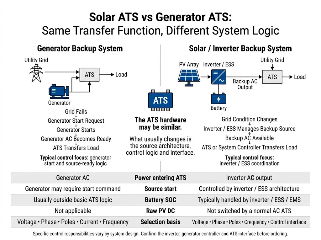
The ATS hardware may be similar, while the surrounding system logic can be very different. A grid-generator system normally has to detect failure of the preferred source, start or enable the generator, verify that generator AC is acceptable, and then transfer the load. In a solar or battery-backup system, an inverter or ESS may already manage source availability and may also participate in the transfer decision. [2] [3]
Buyer meaning: do not select an ATS only by asking for a “solar ATS” or a “generator ATS.” First define the two AC sources, voltage, phase, pole requirement, load current and control sequence.
The most useful comparison is what reaches the ATS, what must happen before transfer, and which device controls the sequence.
| Entscheidungspunkt | Solar / inverter backup | Generator backup |
|---|---|---|
| Source seen by a typical AC ATS | Usable inverter or ESS AC output | Generator AC output |
| Raw PV DC switched by normal AC ATS? | No — not by an AC-only ATS | Not applicable |
| Typical control issue | Inverter / ESS coordination | Generator start and source-ready logic |
| External ATS always required? | No — depends on inverter architecture | Depends on system architecture |
| Main ATS selection basis | Voltage, phase, poles, current and control interface | Voltage, phase, poles, current and control interface |
“Solar” and “generator” describe the application. They do not provide enough information to approve an ATS model.
Generator ATS: the usual grid-to-generator sequence
In a conventional standby arrangement, the utility and generator are the two AC sources feeding the transfer system. The controller monitors source conditions and transfers the load only after the alternate source satisfies the configured acceptance conditions. [2]
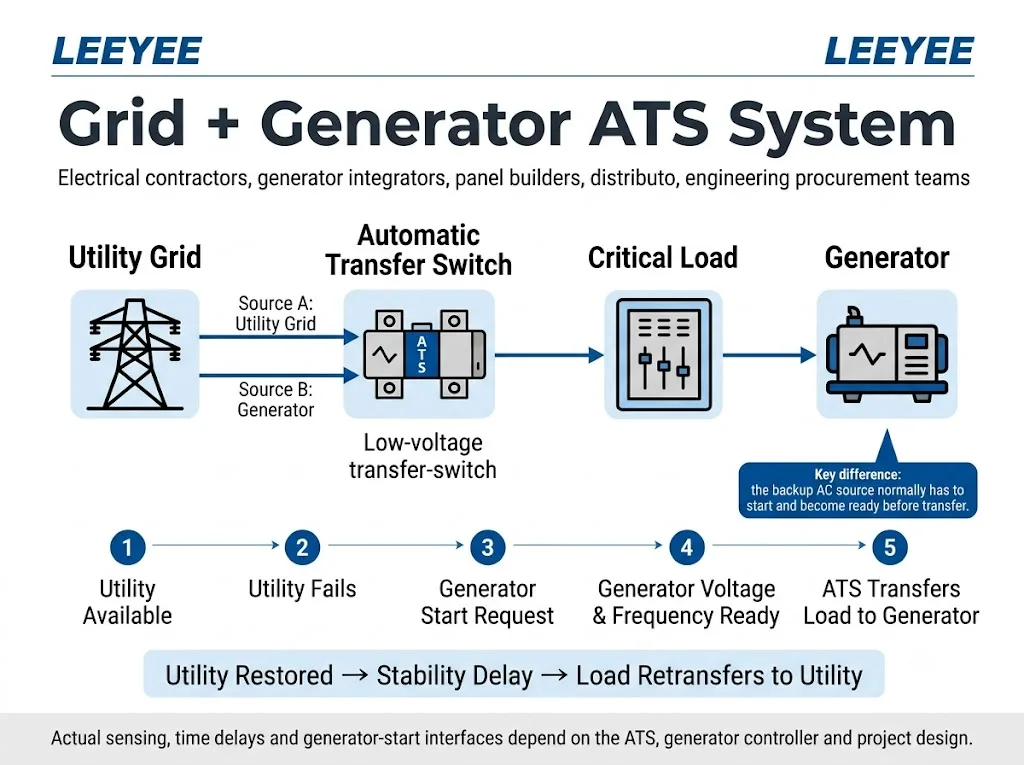
- Normal source is monitored. The ATS or associated controller checks the preferred AC source.
- A source failure is detected. The controller applies its configured detection and delay logic.
- The generator is started where required. The start interface must match the generator controller.
- The alternate source is verified. Engine start does not automatically mean the electrical source is ready.
- The load is transferred. Transfer and retransfer logic remains project-specific.
Solar backup changes the architecture before the ATS
A PV array produces DC power. A conventional AC transfer arrangement should therefore not be visualised as “PV panel → ATS → AC load.” The inverter or ESS converts and manages the energy before a usable AC source reaches an external AC transfer switch.
IEC 60947-6-1 defines transfer switching equipment around the function of transferring loads between power sources; it does not establish a universal “solar ATS” product category with one fixed solar control architecture. [1]
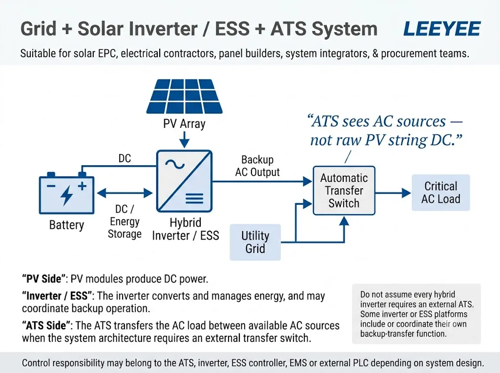
Do not confuse AC transfer with PV DC switching
A normal AC ATS must not be assumed suitable for switching raw PV-string DC. Use switching equipment specifically rated and documented for the actual AC or DC circuit.
Solar ATS vs generator ATS: similar transfer hardware, different system logic
Strompfad
The ATS transfers the load between approved AC sources. Voltage, current, phase, poles and transition method must match the project.
Steuerpfad
The control system decides whether a source is usable, whether another source must start, which source has priority, and when transfer occurs.
Who actually controls the transfer?
Control responsibility depends on the architecture. It should not be assumed from the term “solar ATS” or “generator ATS.”
May monitor source conditions and perform the physical transfer between two AC sources.
Manages generator starting and generator-side operation. Its interface must be coordinated with the transfer system.
May establish backup AC and manage battery or inverter operating logic.
May coordinate multiple sources in more complex hybrid systems.
Important product boundary
A compact LEEYEE ATS should be understood primarily as the dual-source AC transfer device. Generator starting, battery SOC management, inverter energy management, EMS functions and PLC-level hybrid control are separate system functions unless the selected product and project documentation specifically confirm otherwise.
Generator start signal and inverter control are not the same function
A generator may require a start or stop command before it can become an available source. A solar inverter manages a different set of functions and can use manufacturer-specific backup outputs, contacts or communication interfaces.
Therefore, a generator-start dry contact must not automatically be treated as a universal inverter-control interface. Terminal functions and control logic must be checked against the actual ATS, generator and inverter documentation.
Can the same ATS be used for a solar inverter and a generator?
Sometimes — if the electrical and control requirements match.
- Both ATS input sources must be within the documented voltage and frequency range.
- The ATS current rating must suit the intended load.
- Single-phase or three-phase configuration must match the system.
- The required 2P, 3P or 4P arrangement must be confirmed.
- Neutral switching and earthing must be defined for the real system.
- The required transition method must be supported by the ATS.
- Generator-start or remote-control interfaces must be compatible where required.
- The inverter manufacturer must permit the proposed external ATS architecture.
Does every solar inverter need an external ATS?
No. Some inverter and ESS platforms include backup switching functions or use manufacturer-specific transfer devices. Others can work with external switching equipment. Follow the actual inverter system documentation rather than automatically adding an ATS. [3]
Where the LEEYEE compact ATS fits
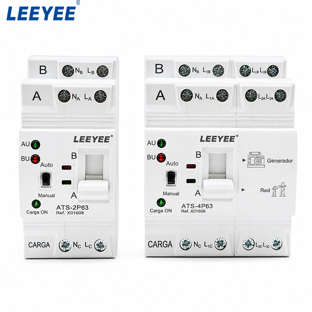
The LEEYEE product shown below is a compact integrated dual-source automatic transfer switch. The actual product image shows compact 2P and 4P configurations, Auto / Manual operating positions, Source A / Source B indications and a load output arrangement.
This product format naturally matches conventional grid + generator dual-source applications. In a suitable solar backup project, the second source may instead be a compatible inverter backup AC output, provided the inverter manufacturer permits an external ATS and all electrical and control requirements match.
What this product should not be presented as
This compact ATS is not a PV-string DC switch, solar EMS, battery SOC controller, generator controller or large multi-source transfer cabinet. More complex closed-transition, bypass-isolation or multi-source architectures require separate engineering evaluation.
Before ordering: send these system details
Need to confirm a LEEYEE ATS for your system?
Send us your two AC sources, voltage, phase, required poles, load current and intended control sequence. For inverter applications, also provide the inverter or ESS model. For generator applications, provide the generator-controller interface where relevant.
FAQ
Is a solar ATS different from a generator ATS?
Not necessarily. The transfer hardware may be similar. The main difference is often the source architecture and control sequence around the ATS.
Can a LEEYEE ATS work with a solar inverter?
It may be possible when the inverter provides a compatible AC backup output, permits an external ATS, and the ATS voltage, current, phase, poles and control logic all match the project. Confirm the actual inverter documentation before selection.
Can this ATS switch raw PV DC?
Do not assume so. The product discussed on this page is positioned as a low-voltage AC dual-source ATS. PV-string DC switching requires equipment specifically rated for the DC circuit.
Does this ATS manage battery SOC?
Battery SOC management should normally be treated as an inverter, ESS or EMS function unless a specific ATS configuration is explicitly documented to provide that function.
Can the ATS start a generator?
Generator-start capability depends on the selected ATS configuration and the generator-controller interface. Do not assume compatibility without checking the wiring and control documentation.
Should I choose 2P or 4P?
That depends on the phase system, neutral arrangement, earthing design and project requirements. The product image shows both 2P and 4P configurations, but final pole selection must follow the actual system design.
Confirm the system before fixing the ATS model
A simple single-line diagram showing Source A, Source B, the ATS and the load is usually more useful than asking only for a “solar ATS” or “generator ATS.”
Referenzen
- IEC — IEC 60947-6-1:2026, Low-voltage switchgear and controlgear – Part 6-1: Multiple function equipment – Transfer switching equipment. Official IEC page.
- Eaton — Automatic Transfer Switches Fundamentals. Technical guidance covering transfer-switch source monitoring, generator applications, transfer sequence and neutral-switching considerations. Eaton technical reference.
- SMA Solar Technology AG — Setting Parameters for Automatic Backup Operation. Documentation describing inverter-based backup operation and automatic transfer switching coordination. SMA documentation.
The diagrams on this page explain common system concepts only. Final ATS selection, wiring, neutral treatment, source coordination and control interfaces must be verified against the actual LEEYEE ATS specification, inverter or generator documentation and project requirements.
