
A generator ATS panel should be designed as a complete backup-power system, not as an ATS placed alone inside a cabinet. The panel builder must coordinate the utility source, generator source, upstream protection, compact ATS, surge protection, generator controller, status signals, cable routing and protected load.
The real engineering question is therefore: how should a compact ATS be integrated into a generator room or backup power cabinet, and what must be confirmed before the ATS model and cabinet drawing are frozen?
Inhaltsübersicht
Schnelle Antwort
In a typical utility-to-generator backup system, the Utility / Normal source and Generator / Emergency source feed the ATS, and the ATS connects the selected source to the protected load. Transfer switching equipment is designed to transfer a load between power-supply sources. [1]
A generator ATS panel design should be developed around two separate paths: the power path from Utility and Generator through protection and the ATS to the load, and the control/status path between the ATS, genset controller, local indication and remote monitoring.
LEEYEE supplies the compact ATS device. The complete cabinet, feeder protection, busbars, cables, SPD arrangement, ventilation, generator controller and final integration are normally designed and verified by the panel builder or system integrator for the specific project.
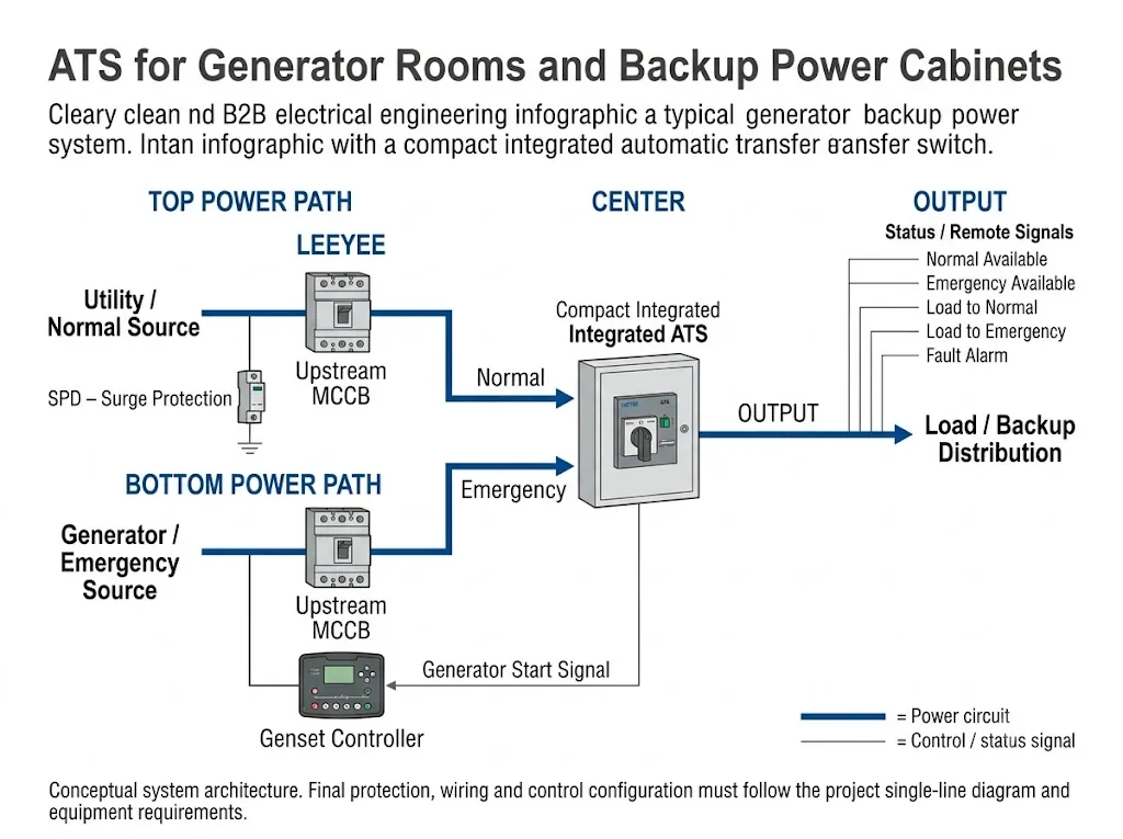
Power Path
Utility → upstream protection → ATS Normal input
Generator → upstream protection → ATS Emergency input
ATS output → protected load
Control & Status Path
ATS / controller ↔ generator start interface
ATS status → local indicators / BMS / PLC where supported
Welche Rolle spielt das ATS in einem Notstromsystem?
IEC 60947-6-1:2026 covers transfer switching equipment used to transfer a load between supply sources. In a generator backup application, the ATS normally sits between the two available sources and the downstream load. [1]
For a conventional utility-generator arrangement, this means one Normal source, usually utility power, one Emergency source, usually the generator, and one load connection on the output side of the ATS. Eaton describes utility-generator as a common two-source transfer-switch arrangement for standby power systems. [5]
What Does Each Device in the Backup Power Cabinet Do?
ATS, MCCB, SPD and generator controller are often shown close together on a cabinet drawing, but they have different functions. Understanding that separation is essential before the panel layout is finalized.
| Gerät | Hauptfunktion | Was bestätigt werden muss |
|---|---|---|
| Kompaktes ATS | Transfers the load between the Normal and Emergency sources. | Rated current, poles, system voltage, transfer logic, dimensions and terminal arrangement. |
| Upstream MCCB / protective device | Provides project-selected feeder protection and isolation. | Fault level, protective-device rating, coordination and conductor protection. |
| SPD | Limits transient overvoltages and diverts surge current. [3] | System voltage, earthing arrangement, SPD type, protection mode, position and coordination. [4] |
| Genset controller | Controls and supervises generator-set operation according to the generator system design. | Start interface, control conditions, alarms, permissives and genset documentation. |
| Status / remote interface | Provides local or remote source and transfer information where supported. | Required contacts, terminal definitions, BMS/PLC interface and model-specific availability. |
Procurement conclusion: the ATS should be selected after the source arrangement, protection concept, physical cabinet space and required control interface are understood. Current rating alone is not enough.
Power Circuit and Control Circuit Should Be Designed Separately
A generator backup cabinet becomes easier to design and troubleshoot when the system is divided into the Stromkreis und die control/status circuit.
Power circuit
The power circuit carries load current. In a typical utility-generator system it includes the Normal source, Emergency source, project-selected upstream protective devices, ATS power poles and outgoing load conductors.
Control and status circuit
The control circuit carries commands and status information rather than load current. Depending on the ATS and generator-control architecture, this may include generator-start commands, source-available signals, transfer-position indication and fault or alarm outputs.

How Does the Generator Start Signal Fit into the System?
In many automatic utility-generator systems, the transfer-switch control monitors the preferred source and initiates generator starting when that source becomes unacceptable. After the generator source reaches acceptable conditions, the load can be transferred to the Emergency source. Cummins documents this general operating sequence for its utility-generator transfer-switch systems. [6]
This does nicht mean that every ATS and genset use one universal start-signal arrangement. The actual interface may depend on ATS controller design, genset controller logic, contact type, control supply and project requirements.
Which ATS Status Signals Should Be Defined?
Generator-room and backup-power panels often require more than a simple Auto/Manual indication. The operator, BMS or PLC may need to know whether each source is available and which source is supplying the load.
Useful project signal points to define include:
- Normal Available — Normal source satisfies the defined availability conditions.
- Emergency Available — Emergency source satisfies the defined availability conditions.
- Load to Normal — the ATS is in the Normal-source position.
- Load to Emergency — the ATS is in the Emergency-source position.
- Fault Alarm — project-defined fault or alarm output where the selected configuration supports it.
These should be treated as functional requirements to confirm. They are not a blanket statement that every compact ATS provides all of these outputs.
If remote supervision is required, define whether the project needs dry contacts, hard-wired digital signals or a communication interface. The selected ATS must then be checked against that requirement before the cabinet schematic is approved.
How Should MCCBs and the ATS Be Coordinated?
The ATS performs source transfer. Feeder protective devices perform protection and isolation functions selected for the electrical design. They are related, but they are not interchangeable.
Prospective fault current, conductor protection, protective-device characteristics and the ATS manufacturer's declared ratings all affect the completed design. IEC 60947-6-1:2026 covers transfer switching equipment, while IEC 61439-1 and IEC 61439-2 provide the construction and verification framework for low-voltage switchgear and controlgear assemblies. [1][2]
Where Does the SPD Fit in the ATS Cabinet?
The SPD performs a completely different function from the ATS. IEC 61643-11:2025 covers surge protective devices intended to limit transient overvoltages and divert surge currents in AC low-voltage power systems. [3]
IEC 60364-5-53 provides requirements for the selection and erection of protective, isolation, switching, control and monitoring devices, including the SPD-related provisions in Clause 534. [4]
The exact SPD position, protection mode, earthing connection, conductor routing and upstream protective arrangement must therefore be based on the real single-line diagram, earthing arrangement and surge-protection design.
How Should a Compact ATS Be Arranged Inside the Cabinet?
A compact integrated ATS can reduce the switching-device footprint inside a backup power cabinet, but the panel still needs enough room for power terminals, cable bending, upstream protective devices, SPD, control wiring, manual operating access and ventilation.

IEC 61439-1 establishes general construction, technical-characteristic and verification requirements for low-voltage switchgear and controlgear assemblies, while IEC 61439-2 applies to power switchgear and controlgear assemblies. The equipment installed inside the cabinet must therefore be considered as part of the complete assembly rather than as isolated products. [2]
1. Confirm cable entry before fixing the ATS position
Check whether the Normal source, Emergency source and load cables enter from the top, bottom or another defined zone. The ATS position and orientation must suit the real terminal arrangement and leave enough space for conductor bending and termination.
2. Keep the operating area accessible
If the selected ATS provides or requires manual operation, the cabinet layout must not block its operating mechanism. Required access for operation, inspection and maintenance should be checked against the actual ATS instructions.
3. Do not copy a universal clearance value
There is no single spacing value that should be copied into every generator ATS panel. Required clearance depends on product dimensions, terminals, conductor size, enclosure arrangement, heat dissipation and the assembly design.
4. Treat temperature rise as an assembly issue
ATS, MCCBs, SPD, terminals and control equipment all contribute to the physical and thermal conditions inside the cabinet. IEC 61439-1 and IEC 61439-2 include temperature-rise verification within the assembly framework. [2]
5. Keep power and control wiring understandable
Large power conductors and small control/status conductors have different routing and termination requirements. The cabinet should allow both wiring systems to remain clear, maintainable and consistent with the approved schematic.
A Practical Generator ATS Panel Design Sequence
For a panel builder or genset integrator, the safest sequence is to define the system first and then select the ATS inside that system.
-
Define the two sources.
Confirm Utility / Normal and Generator / Emergency voltage, frequency, phase arrangement and operating concept. -
Define the protected load.
Confirm rated current, load characteristics and the required continuity strategy. -
Define poles and neutral arrangement.
Confirm whether the project requires 2P, 3P or 4P and how neutral switching relates to the actual system and earthing design. -
Define upstream protection.
Confirm protective devices, available fault current and the required coordination using project calculations and manufacturer data. -
Define the generator-start interface.
Confirm the required ATS-to-genset start command and any feedback, permissive or alarm requirements. -
Define local and remote status.
List the exact source, position and alarm information required by the operator, BMS or PLC. -
Check the physical cabinet.
Compare ATS dimensions and terminal arrangement with cable entry, conductor bending, operation, ventilation and maintenance access. -
Freeze the ATS model only after the drawings agree.
The ATS datasheet, GA drawing, single-line diagram and control schematic should all describe the same final configuration.
What LEEYEE Supplies — and What the Panel Builder Integrates
The system diagrams above explain how an ATS fits into a generator backup system. The product below shows the type of compact integrated ATS device supplied by LEEYEE for installation inside a customer-designed panel.
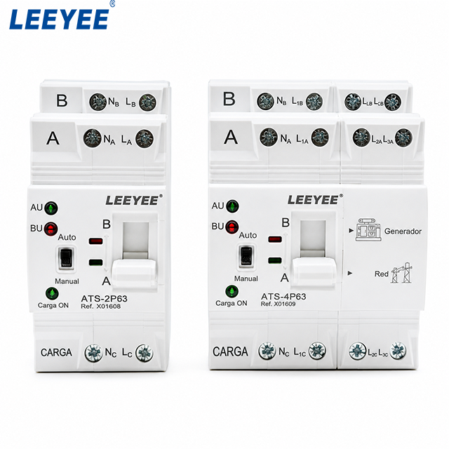
LEEYEE supplies the compact integrated ATS device for customer-designed backup power cabinets, ATS panels and generator-room distribution systems.
The complete generator room, enclosure, busbars, feeder protection, cabling, ventilation, SPD arrangement, generator controller, BMS/PLC system and assembly verification remain project-level integration work unless separately defined in an agreed supply scope.
The product image also illustrates why the distinction matters. The compact ATS itself provides the source-transfer function and a compact operating interface, while the surrounding cabinet still has to provide the upstream protection, conductor routing, terminals, surge protection and any project-specific external control or monitoring equipment.
Visible product features such as two source inputs, load output, Auto/Manual operation and different pole configurations can help the panel builder understand the physical integration concept. However, additional functions such as remote contacts, alarm outputs or BMS communication must still be confirmed against the exact ATS model and its technical documentation.
An ATS datasheet therefore cannot replace a complete cabinet design. The panel builder must combine the actual ATS data with the project single-line diagram, control schematic, generator documentation and applicable assembly requirements.
It also prevents a common procurement misunderstanding: a request for a “generator ATS cabinet” may refer either to a complete panel or only to the switching device. The enquiry should state clearly which scope is required.
What Should You Send Before Ordering the ATS?
A good ATS enquiry should contain enough information for the supplier to confirm both electrical suitability and physical integration.
Generator ATS Panel / Backup Cabinet Checklist
- Einliniendiagramm
- Cabinet GA or available mounting space
- Systemspannung und Frequenz
- Einphasiges oder dreiphasiges System
- Erforderlicher Nennstrom
- Required 2P / 3P / 4P configuration
- Utility / Normal source details
- Generator / Emergency source details
- Erdung und Neutralleiteranordnung
- Informationen zu vorgeschalteten Schutzvorrichtungen
- Cable entry direction
- Required generator-start interface
- Required local status indication
- Required remote status / alarm outputs
- BMS or PLC interface requirement, if any
- Required standard or project specification
- Mengen- und OEM-Anforderungen
Need to Confirm an ATS for Your Generator Backup Cabinet?
Send the cabinet drawing, system voltage, current, pole configuration, generator information, available installation space and required control signals. LEEYEE can use these details to confirm the compact ATS configuration that should be evaluated for your panel.
Common Generator ATS Panel Design Mistakes
Selecting the ATS only by ampere rating
Current rating is important, but a usable selection also depends on system voltage, poles, source arrangement, protection, dimensions, terminal access and control requirements.
Assuming the ATS replaces upstream protection
The ATS is transfer switching equipment. Feeder protection and complete assembly design still require separate engineering confirmation. [1][2]
Adding an SPD without checking the actual installation
SPD selection and erection depend on the electrical system, earthing arrangement and surge-protection concept. The SPD should be selected for the actual project rather than added as a generic accessory beside the ATS. [3][4]
Assuming every ATS has the same generator-start terminals
Generator-start functionality is common in many utility-generator systems, but the actual terminal arrangement, contact ratings and control conditions remain model-specific. [6]
Ignoring cable and manual operating space
A compact ATS saves space only if the installer can still terminate conductors, operate the mechanism as required and access the device for inspection or maintenance.
Using a conceptual image as a construction drawing
The diagrams on this page explain system relationships. They are not dimensional drawings, terminal diagrams, short-circuit studies or approved panel schematics.
FAQ for Generator Rooms and Backup Power Cabinets
What is the basic generator ATS panel design?
A basic generator ATS panel has two source paths—Utility / Normal and Generator / Emergency—feeding the ATS, with the ATS output supplying the protected load. Upstream protection, generator controls, SPD and status functions are designed around that power path according to the project requirements.
Does an ATS need an MCCB in a generator backup cabinet?
The ATS and protective devices perform different functions. Whether an MCCB or another protective arrangement is required at a particular point must be determined from the project protection design, source characteristics, conductor protection and ATS ratings.
Can the ATS directly start the generator?
Many utility-generator transfer systems use the ATS control to initiate generator starting when the Normal source becomes unacceptable. [6] The actual contact type, control voltage, terminal numbers and operating logic must still be confirmed for the selected ATS and genset controller.
Should the SPD be installed before or after the ATS?
There is no universal answer without the project single-line diagram. SPD location and protection mode depend on the installation, earthing arrangement, required surge-protection concept and coordination. [3][4]
Can ATS status be sent to a BMS or PLC?
Yes, where the selected ATS or control configuration provides the required outputs or approved communication interface. Normal Available, Emergency Available, Load to Normal, Load to Emergency and Fault Alarm should be treated as project signal requirements that must be confirmed against the actual ATS model.
How much space should be left around a compact ATS?
Do not use a generic clearance number. Check the actual ATS instructions, conductor size, terminal geometry, cable bending, enclosure arrangement, ventilation, operating access and assembly thermal design. [2]
Does LEEYEE supply the complete generator room or ATS cabinet?
Diese Seite konzentriert sich auf das LEEYEE compact ATS device as a component inside a customer-designed backup power cabinet or generator-room electrical system. Complete cabinet and system integration should be defined separately with the panel builder or system integrator.
Referenzen
- IEC — IEC 60947-6-1:2026, Low-voltage switchgear and controlgear — Part 6-1: Multiple function equipment — Transfer switching equipment. Used for the scope and function of transfer switching equipment.
- IEC — IEC 61439-1:2020 and IEC 61439-2:2020, Low-voltage switchgear and controlgear assemblies — Part 1: General rules und Part 2: Power switchgear and controlgear assemblies. Used for assembly-level construction, technical characteristics, temperature rise and verification context.
- IEC — IEC 61643-11:2025, Low-voltage surge protective devices — Part 11: Surge protective devices connected to AC low-voltage power systems — Requirements and test methods. Used for the function and scope of AC low-voltage SPDs.
- IEC — IEC 60364-5-53:2019 + AMD1:2020 + AMD2:2024, Low-voltage electrical installations — Part 5-53: Selection and erection of electrical equipment — Devices for protection for safety, isolation, switching, control and monitoring. Used for installation-level selection and erection context, including SPD provisions.
- Eaton, Grundlagen automatischer Umschalter (ATS). Used as an established manufacturer technical reference for Normal source, alternate source, load and utility-generator source arrangements.
- Cummins, GTEC Transfer Switch. Used as a manufacturer technical example of source monitoring, generator starting and utility-to-generator load-transfer sequence. Product-specific Cummins functions are not presented as LEEYEE specifications.