
Verwenden Sie Typ 1+2 auf der Eingangsseite
Dies wird üblicherweise für Hauptverteilungen und Gebäude mit äußerem Blitzschutzsystem in Betracht gezogen, wenn ein Gerät sowohl Blitzstrom- als auch Überspannungsschutz leisten muss.
Kombinierter Blitzstrom- und Überspannungsschutz für Hauptverteilungen, Verteiler, Schaltschrankbauer und OEM-Projekte. Senden Uc, Iimp, Pole und Erdungssystem um das korrekte Modell und den Dokumentationsumfang zu bestätigen.
Ein Typ 1+2 SPD sollte nicht allein nach der Polzahl ausgewählt werden. Überprüfen Sie den Installationsort, die Anordnung von Neutralleiter und PE, den erforderlichen Iimp-Pfad, Uc sowie den externen Vorsicherungsschutz.
Dies wird üblicherweise für Hauptverteilungen und Gebäude mit äußerem Blitzschutzsystem in Betracht gezogen, wenn ein Gerät sowohl Blitzstrom- als auch Überspannungsschutz leisten muss.
3P, 4P und 3P+N sind keine austauschbaren Bezeichnungen. Die korrekte Anordnung hängt von den TT-, TN-S- oder TN-C-Leitern ab und davon, ob das Design eine 4+0- oder 3+1-Schutzschaltung verwendet.
Bei MOV+GDT-Anordnungen können die L-N- und N-PE-Werte variieren. Fragen Sie nach, ob Iimp pro Pol, pro Schutzpfad oder als Gesamtwert angegeben ist.
| AC-System | Gängige Ausgangskonfiguration | Schutzkonzept | Wichtige Bestätigung vor der Bestellung |
|---|---|---|---|
| Einphasig TN-S / TT | 1P+N oder verifizierte 2P-Anordnung | L-N plus N-PE oder All-Mode-Anordnung gemäß Auslegung | Uc, N-PE-Pfad, Iimp-Verteilung und Backup-Schutz |
| Dreiphasig TN-C | 3P | Phasen-zu-PEN-Leiter ohne separaten Neutralleiter am Installationspunkt | Tatsächliche PEN-Anordnung, Uc und Kurzschlussbedingungen |
| Dreiphasiges TN-S | 4P oder 3P+N | 4+0 oder 3+1 je nach Projekttopologie | Neutralleiterbehandlung, N-PE-Pfad, Up und Leiterführung |
| Dreiphasiges TT | Verifizierte 3P+N-Anordnung | Üblicherweise L-N-MOV-Pfade plus N-PE-GDT-Pfad | N-PE-Impulsstrom, Folgestrom und Dokumentationsabdeckung |
Die Klassifizierung ändert die Testparameter, die erwartete Installationsphase und die Beschaffungsprüfungen. Die folgende Seite konzentriert sich ausschließlich auf die kombinierte Typ 1+2-Produktreihe.
Ausgelegt auf den 10/350μs-Blitzstromtest und die Iimp-Leistung.
Ein SPD, das sowohl für 10/350μs-Blitzstrom- als auch für 8/20μs-Stoßstromleistung bewertet wurde.
Ausgelegt auf den 8/20μs-Test unter Verwendung von In und Imax als Hauptstromparameter.
Sechs bestehende Konfigurationen decken Einzelpfad-, Mehrpol- und MOV+GDT-Anordnungen ab. Genaue Daten zu Uc, Up, Iimp, In und Vorsicherung werden mit der ausgewählten Version abgeglichen.
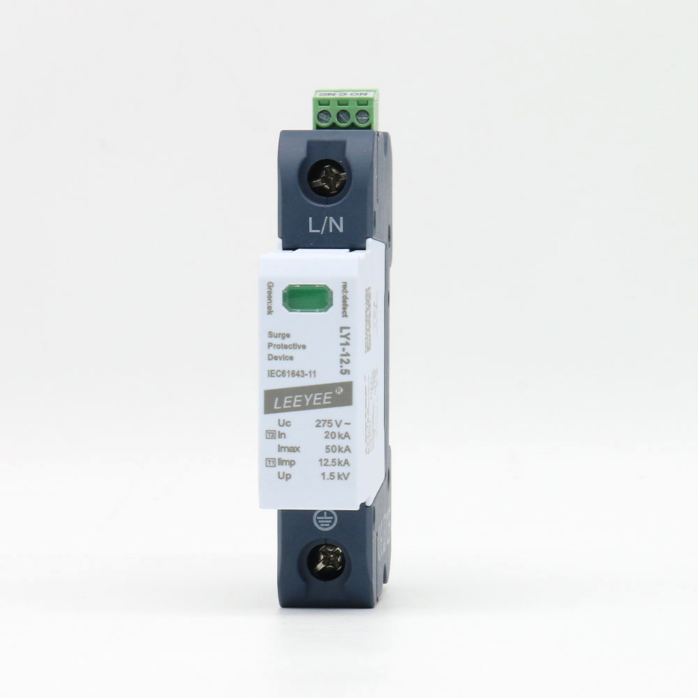
Einpoliges steckbares Typ-1+2-Modul für einen geprüften Schutzpfad.
Versionen mit höherem Uc können abweichende Iimp- und Vorsicherungsgrenzen haben. Bestätigen Sie das exakte Spannungssuffix.
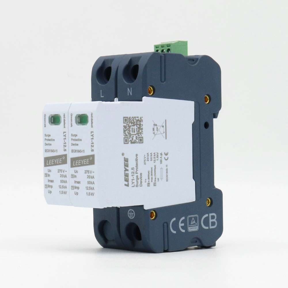
Zweipolige steckbare Baugruppe für Systemdesigns, die zwei geschützte Leiter erfordern.
Ein 2P-Gehäuse allein ist kein Nachweis für die korrekte L-N/N-PE-Topologie. Überprüfen Sie den internen Schutzmodus.
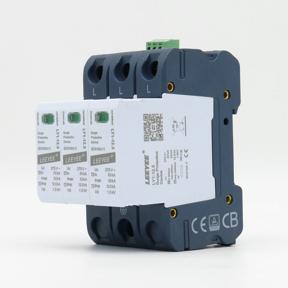
Dreipoliger steckbarer Typ 1+2 Überspannungsschutz für geprüfte Drei-Leiter-Anordnungen.
Häufig dort in Betracht gezogen, wo am Installationspunkt kein separater Neutralleiter geschützt ist. Überprüfen Sie das tatsächliche System.
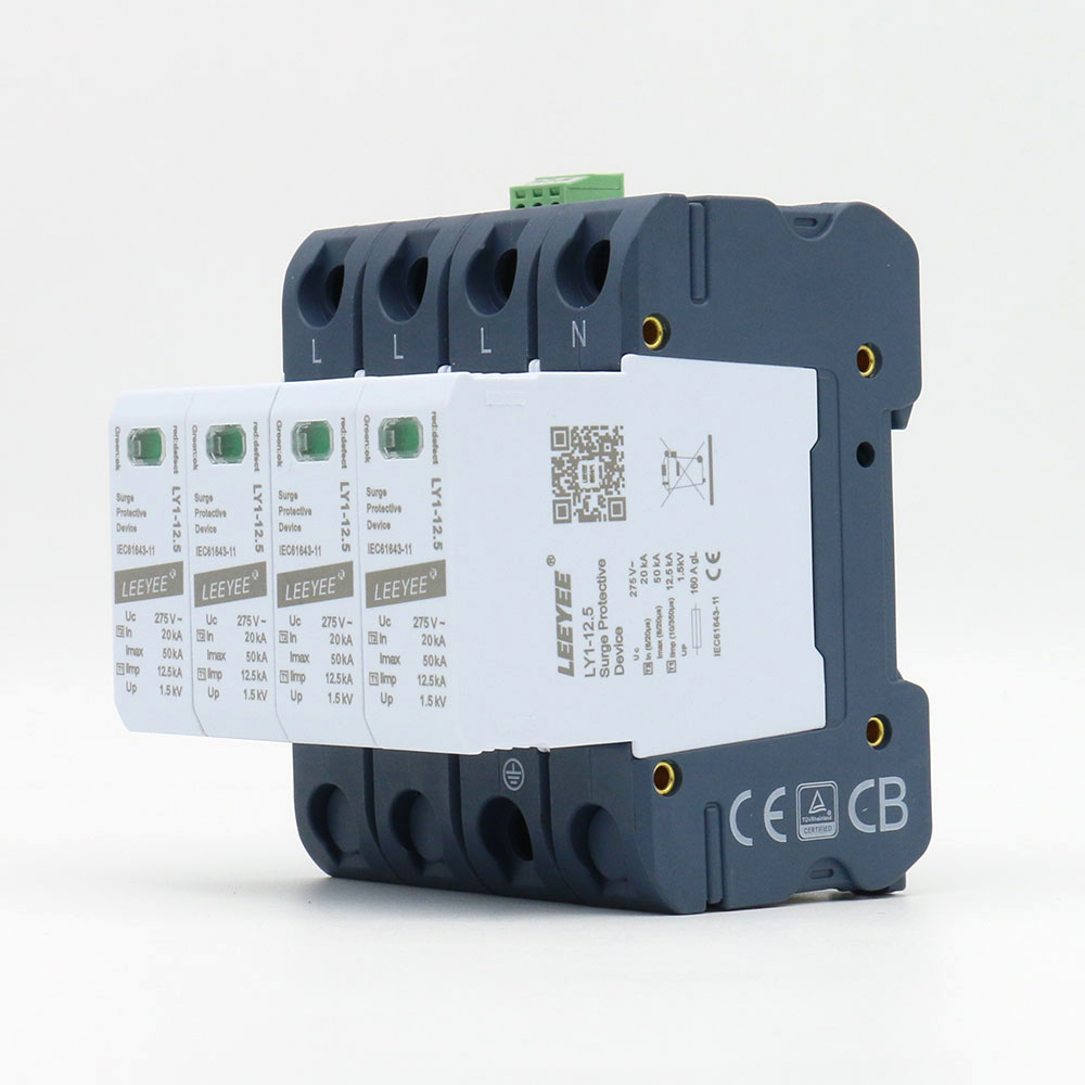
Vierpoliger steckbarer Typ 1+2 Überspannungsschutz für eine geprüfte 4+0-Schutzanordnung.
Betrachten Sie „4P“ nicht automatisch als identisch mit einer 3+1 MOV+GDT-Konfiguration. Überprüfen Sie die Schutzpfade.
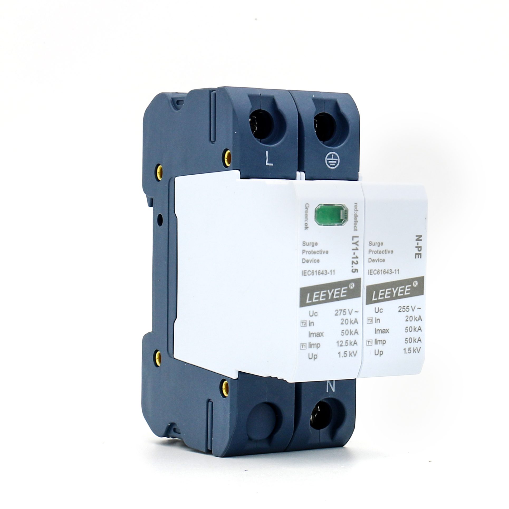
L-N MOV plus N-PE GDT-Anordnung für eine verifizierte einphasige Topologie.
Bestätigen Sie das N-PE-Folgestromverhalten, Up und die erforderliche externe Vorsicherung für die exakte Version.
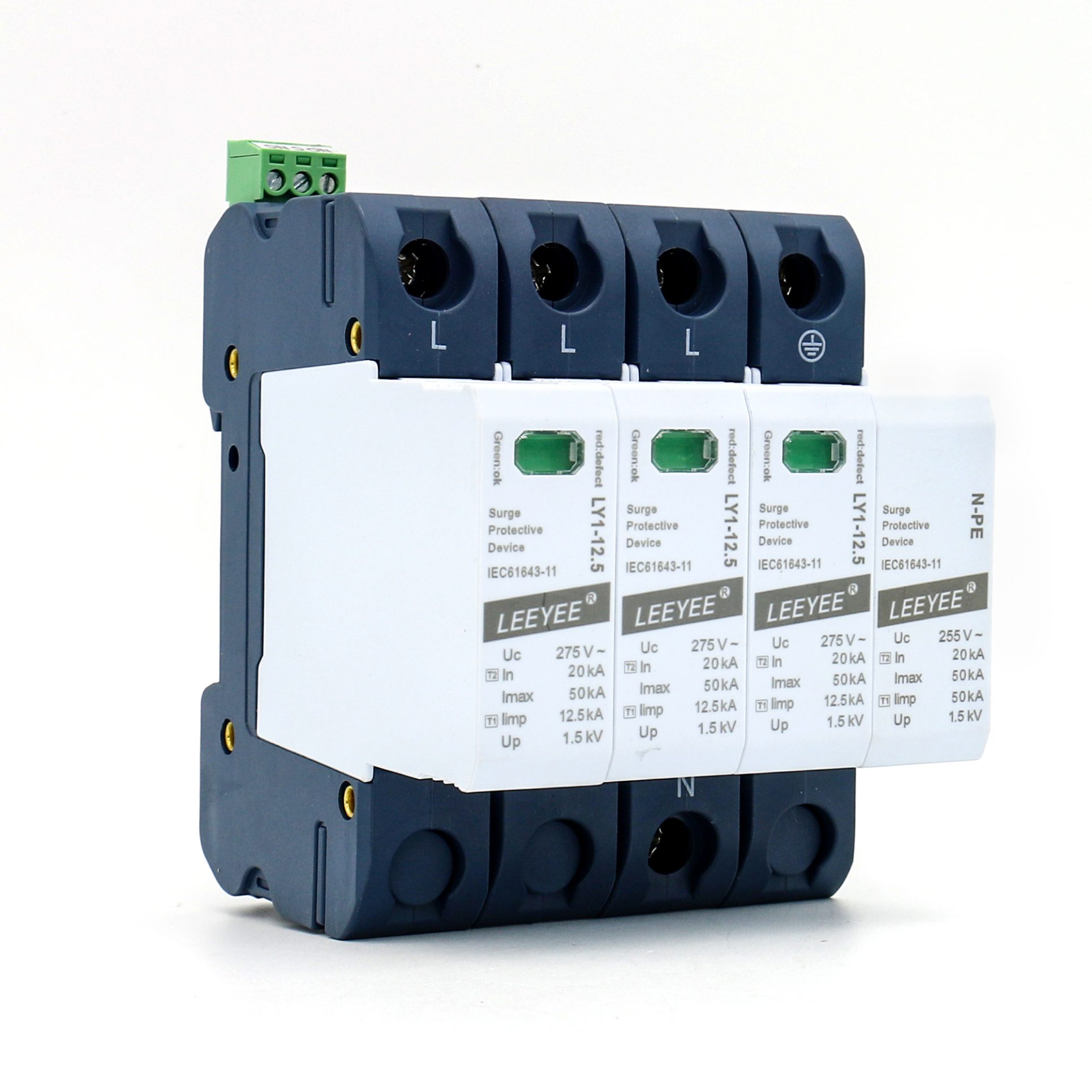
Drei L-N MOV-Pfade plus ein N-PE GDT-Pfad für eine verifizierte 3+1-Topologie.
L-N- und N-PE-Werte unterscheiden sich absichtlich. Überprüfen Sie jeden Pfad, anstatt sich auf einen einzelnen Strom-Headline-Wert zu verlassen.
Ein Modell kann nach Typ und Polzahl korrekt aussehen, ist aber dennoch ungeeignet, wenn der Strompfad, Uc, die Topologie oder der Vorsicherungsschutz nicht verifiziert wurden.
Fragen Sie nach, wie der deklarierte 10/350μs-Strom verteilt ist. Ein Headline-Wert kann sich je nach Modell auf einen Pol, einen Pfad oder einen kompletten N-PE-Pfad beziehen.
Wählen Sie Uc basierend auf der tatsächlichen Spannung zwischen Phase und Neutralleiter oder Phase und Erde, den Toleranzen und der Belastung durch vorübergehende Überspannungen. Ein höherer Uc-Wert ist nicht automatisch besser.
Eine 4P-MOV-Anordnung und eine 3P+N-MOV+GDT-Anordnung erzeugen unterschiedliche Pfade. Bestätigen Sie Neutralleiterführung, das N-PE-Verhalten und das Erdungssystem des Projekts.
Der interne thermische Trennschalter des SPD ersetzt nicht den vollständigen externen Kurzschlussschutz. Überprüfen Sie den maximale Vorsicherung, den prospektiven Fehlerstrom und die Leiterlänge.
Gerätefotos dienen als unterstützender Nachweis, nicht als Ersatz für einen modellspezifischen Prüfbericht. Der exakte Typ, Uc, die Pole und die Markenkonfiguration müssen weiterhin mit dem Dokumentationsumfang übereinstimmen.
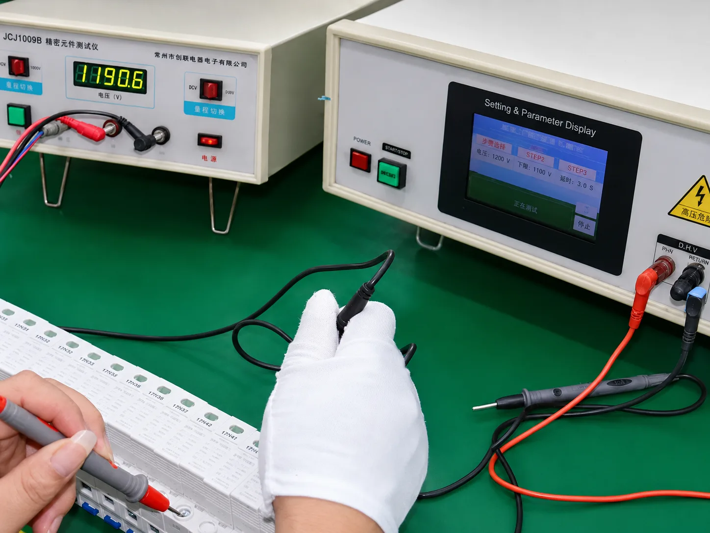
Kernschutzkomponenten werden geprüft, bevor sie Teil einer fertigen SPD-Baugruppe werden.
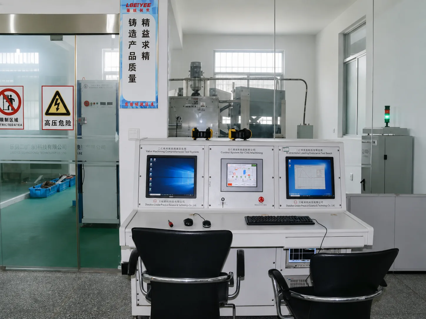
Die Beschaffung von Typ 1+2 erfordert Nachweise sowohl für die Blitzstrom- als auch für die Überspannungsschutzleistung gemäß dem exakten Modell.
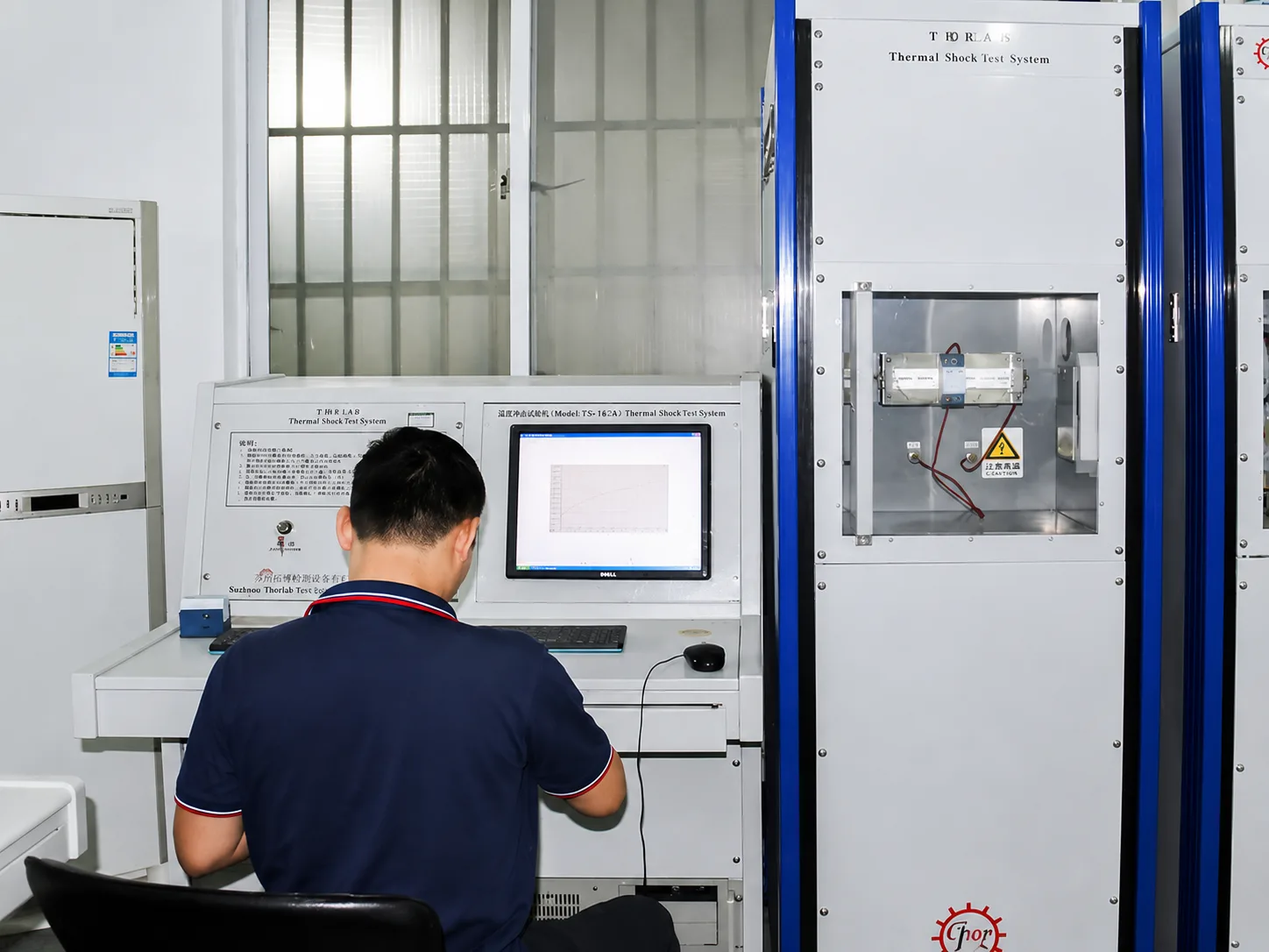
Das thermische Verhalten ist wichtig, da die Alterung von MOV und die Belastung durch anormale Spannungen ein Sicherheitsrisiko darstellen können, wenn die Trennung unzuverlässig ist.
Dokumentengrenze: Die Verfügbarkeit von Zertifizierungen und Prüfunterlagen hängt vom jeweiligen Modell, der Spannung, dem SPD-Typ, der Polkonfiguration, der Marke und den Herstellerangaben ab. Bitte reichen Sie die erforderliche Version zur Bestätigung ein.
Für Distributoren, Schaltschrankbauer und Private-Label-Käufer ist die kommerzielle Freigabe erst abgeschlossen, wenn das gewählte Modell und alle kundenseitigen Unterlagen dasselbe Produkt beschreiben.
Teilen Sie uns den Zielmarkt, das System, die Menge und die Branding-Anforderungen mit, damit LEEYEE das entsprechende Modell und die verfügbare Dokumentation identifizieren kann.
Ein kurzer Freigabeprozess verringert das Risiko, das richtige Gehäuse mit der falschen elektrischen oder dokumentarischen Konfiguration zu bestellen.
Diese Antworten decken die häufigsten Beschaffungsfehler ab. Für eine Modellempfehlung senden Sie uns bitte die tatsächliche Systemspannung, die Erdungskonfiguration, die Anzahl der Pole und die Menge.
Markenklärung: LEEYEE ist die Produktmarke. CNSPD.com ist die Überspannungsschutz-Plattform von LEEYEE für globale Einkäufer.
Senden Sie uns jetzt die wesentlichen Projektdetails. Wir werden diese nutzen, um das geeignete Typ 1+2-Modell, den Dokumentationsumfang und die Angebotsanforderungen zu bestätigen.
Ihre Projektdetails werden verwendet, um das geeignete Modell, den Dokumentationsumfang und die Angebotsanforderungen zu prüfen.