
Selecting a standby generator ATS is not simply a matter of matching the generator kW rating. The transfer switch must match the actual load current, system voltage, phase arrangement, neutral design, generator control interface, transfer sequence and project protection requirements.
This guide is for generator-set integrators, panel builders, electrical contractors, distributors and project procurement teams that already know a standby generator is required and now need to specify the ATS correctly.
The focus is ordinary compact open-transition utility-to-generator switching. Closed-transition paralleling, bypass-isolation assemblies, large service-entrance transfer equipment and zero-interruption systems require different engineering solutions.
Inhaltsübersicht
Quick Answer: What ATS Do You Need for a Standby Generator?
Start with the load. Confirm continuous load current and load type first. Then match voltage, phase and pole arrangement. Finally, confirm the generator start interface, source-acceptance logic, transfer delays and protection coordination before fixing the ATS model.[2]
| Siehe | Bestätigen | Bedeutung für Käufer |
|---|---|---|
| Laststrom | Continuous design current and load characteristics | Defines the basic current requirement |
| Spannung | Normal and generator source voltage | Both sources must match the ATS rating |
| Phase | Einphasig oder dreiphasig | Affects switching and monitoring arrangement |
| Neutral | Solid or switched neutral | Depends on system grounding design |
| Generator control | Required start / stop interface | ATS and genset controls must be compatible |
| Timing | Start, transfer, retransfer and cooldown logic | Defines system response after source changes |
| Load duty | Resistive, lightly inductive, motor or mixed | Rated amperes alone do not define switching suitability |
1. Start With the Standby Power Architecture
A basic standby-generator system has two sources and one load. Utility power is normally the Normal source. The generator is the Emergency source. The ATS connects the load to the appropriate source according to its control logic.
In an open-transition system, the load is disconnected from one source before connection to the other. The two sources are not intentionally paralleled during transfer.[1]
The power path and the generator-control path should be treated as separate engineering questions. The ATS must carry the load current correctly, while the generator controller must receive the correct command and reach acceptable electrical conditions before transfer is allowed.[2][3]
2. Size the ATS From the Load — Not Generator kW Alone
The ATS must carry the design load within its rated operating conditions. Generator capacity is important system information, but generator kW or kVA does not by itself define the correct transfer-switch rating.
First determine the actual continuous load current. Then identify the load characteristics. Heating loads, transformers, pumps, compressors and motors do not impose the same switching duty.
Cummins transfer-switch application guidance separates continuous-current rating from switching-duty considerations and explains that IEC utilisation categories distinguish different load characteristics, including lightly inductive and motor-related duties.[2]
A larger ampere rating does not automatically make an ATS suitable for every load. Utilisation category, load duty, short-circuit conditions and protection coordination must also be checked against the exact product data and project design.[1][2]
Information to prepare before sizing
- Continuous design load current
- Generator kW or kVA
- Largest motor or significant inrush load, if applicable
- Normal and generator source voltage
- Required utilisation category, if specified
- Prospective short-circuit current where required for coordination
- Vorgeschaltete Schutzeinrichtung
3. Match Voltage and Phase Before Choosing the Pole Arrangement
Confirm the operating voltage and frequency of both sources before selecting the ATS. The normal source and generator must also provide the phase arrangement required by the load.
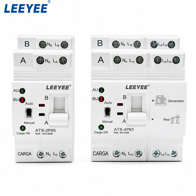
The LEEYEE compact family shown above includes ATS-2P63 and ATS-4P63 configurations. A 2P model is relevant to certain single-phase systems, while a 4P model can be relevant where four conductors must be transferred.
Do not use the shortcut “three phase always means 4P.” Transfer-switch designs may use a solid neutral or a switched neutral. The correct arrangement depends on grounding architecture, generator neutral bonding and whether the alternate source is treated as a separately derived system.[4]
Engineering confirmation: if the grounding arrangement, neutral bond or single-line diagram is uncertain, confirm the neutral-switching requirement with the project electrical engineer before fixing the ATS pole count.
4. Confirm the Generator Start Interface
The real ATS-4P63 product image identifies generator and grid source roles on the front panel. This supports the intended generator/grid transfer application, but the front-panel markings alone do not prove which generator-start interface is available on every model.
Before ordering, confirm what start / stop interface the generator controller requires and whether the exact ATS model provides the required connection.
In a typical standby arrangement, the transfer-control system issues a start request after the normal source is judged unacceptable. The generator controller then handles cranking, engine start and voltage/frequency build-up before the emergency source can be accepted.[2][3]
Do not infer a two-wire dry-contact output, dedicated terminal number or communication protocol from the product appearance alone. Confirm the start-interface wiring from the technical documentation for the exact ATS and generator controller.
5. Confirm the Required Delay Logic
There is no universal best delay setting for every standby generator. The required timing depends on the generator, controller, load and project specification.
| Timing Function | Zweck | Was zu bestätigen ist |
|---|---|---|
| Failure / start delay | Avoids reacting immediately to a brief normal-source disturbance | When should the generator start? |
| Transfer delay | Allows the emergency source to reach acceptable conditions | When is the generator ready for load? |
| Retransfer delay | Allows restored utility power to remain stable before retransfer | How long should Normal be verified? |
| Cooldown | Allows generator operation after the load returns to Normal before shutdown | What does the genset manufacturer require? |
Controller terminology and available timer adjustments vary by model. Confirm the functions actually provided by the selected LEEYEE ATS instead of assuming every timer is independently adjustable.
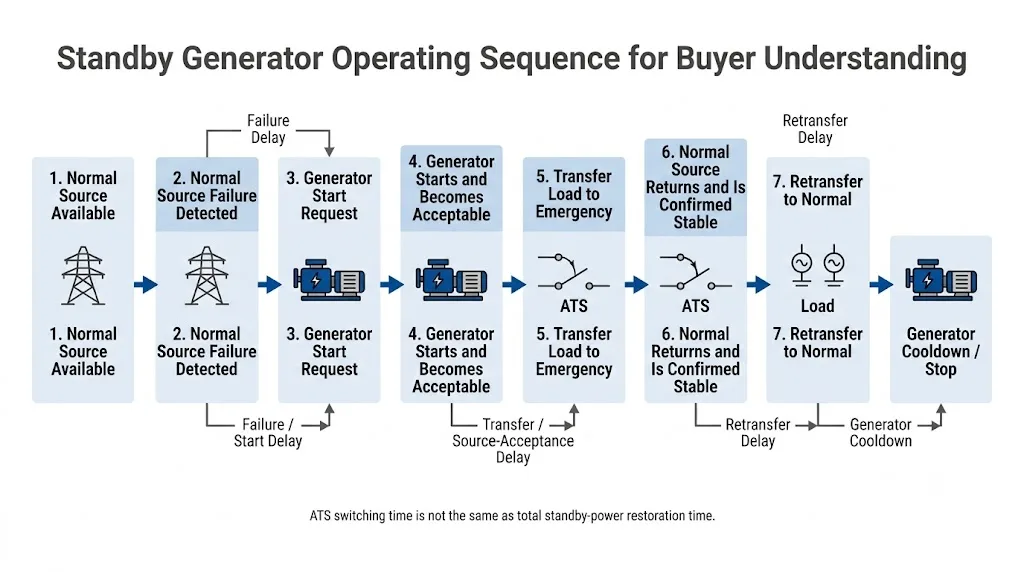
One distinction is especially important: ATS switching time is not the same as total standby-power restoration time. A generator must first receive the start request, crank, accelerate and produce acceptable electrical output before the load can be transferred.[2][3]
6. Understand the Actual LEEYEE Front-Panel Indicators
General ATS engineering documents often use terms such as Normal Available, Emergency Available, Load on Normal und Load on Emergency. These terms explain the operating logic, but they should not be presented as the exact words printed on this product.
On the real ATS-2P63 and ATS-4P63 front panels shown above, the visible markings include:
- A / B — identification of the two source positions
- AU / BU — source-related indication labels visible on the front panel
- Auto — automatic operating mode
- Bedienungsanleitung — manual operation
- Carga ON — load-on indication visible on the product shown
- Generador / Red — generator and grid markings visible on the ATS-4P63
A source being available is not necessarily the same as the load being connected to that source. The exact meaning of each indication and operating condition should be confirmed from the model documentation.
Do not claim unsupported alarm or communication functions. The product image does not by itself prove a dedicated Fault Alarm output, remote alarm contact, Modbus function or BMS interface. These functions must be verified model by model.
7. Open Transition Is the Normal Starting Point for Compact Standby Systems
Open transition is a break-before-make transfer method. The load is disconnected from the first source before connection to the second source, creating an intentional interruption during transfer.[2]
For ordinary standby loads that can tolerate this interruption, a compact open-transition ATS is a practical starting point for selection.
It should not be confused with a UPS or no-break system. Loads requiring uninterrupted power, synchronized source paralleling, closed transition or bypass isolation need a different engineered solution.
8. Do Not Treat This Compact ATS as a Whole-Building Service-Entrance Switch
The LEEYEE ATS-2P63 and ATS-4P63 shown here are compact devices intended for installation within suitable low-voltage distribution or control arrangements. They should not automatically be treated as whole-building service-entrance transfer switches simply because the current rating appears sufficient.
Before specifying a compact ATS, confirm:
- Installation position in the distribution system
- Upstream disconnect and protective device
- Panel or enclosure suitability
- Verfügbarer Kurzschlussstrom
- Required local standard and approval scope
- Whether the project requires service-entrance-rated equipment or another specialised transfer assembly
9. Current Rating Is Only One Part of Product Approval
IEC 60947-6-1 covers low-voltage transfer switching equipment within its stated scope. The current edition is IEC 60947-6-1:2026, Ausgabe 4.0.[1]
A standard reference does not prove that every ATS model meets every project requirement. Model-specific technical documentation, test evidence and certificate scope still need to be verified.
Load duty
IEC utilisation categories distinguish different switching duties. This is especially important when the standby load includes motors, pumps, compressors or other equipment with significant inductive or starting characteristics.[2]
Short-circuit coordination
The available fault current at the installation point, ATS short-circuit capability and upstream protective device must be checked together according to the product data and applicable project requirements.[1][2]
10. Use This Selection Sequence Before Fixing the ATS Model
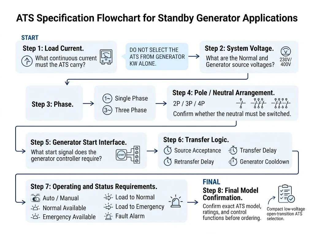
- Define the load. Record continuous current and identify significant motor or inrush loads.
- Confirm both sources. Record utility and generator voltage, frequency and phase.
- Confirm the neutral design. Determine whether the neutral remains solid or must be switched.
- Check the genset controller. Provide its start / stop interface requirement.
- Confirm timing needs. Define source-acceptance, transfer, retransfer and cooldown behaviour.
- Confirm transition type. Use open transition only when the load can tolerate the interruption.
- Check protection coordination. Review fault current and upstream protective devices.
- Verify the exact model. Confirm ratings, terminals, dimensions, functions and applicable compliance documents.
11. Typical B2B Selection Scenarios
Commercial backup distribution panel
A commercial panel uses utility power as Normal and a standby generator as Emergency. Once load current and voltage are known, the remaining decisions include phase, neutral arrangement, generator start interface, transfer logic and protection coordination.
Single-phase project considering the ATS-2P63
The 2P model shown in the real product image is relevant to compact single-phase applications where two conductors must be transferred. The exact voltage, neutral arrangement and grounding requirements still need to be confirmed before the model is fixed.
Three-phase project considering the ATS-4P63
The 4P model shown can support applications where four conductors are required to switch, but a three-phase four-wire system does not automatically mean that every project requires a 4P ATS. Grounding and neutral treatment must be confirmed first.[4]
Factory panel with motor loads
If the standby load contains pumps, compressors or fans, provide the motor details before assuming the compact ATS is suitable. Load-duty suitability must be checked against the exact product rating and application requirements.[2]
12. Where the LEEYEE Compact ATS Fits
The real product shown on this page is a compact LEEYEE automatic transfer switch family with ATS-2P63 and ATS-4P63 front-panel configurations. The products use an integrated operating mechanism and front-panel Auto / Manual control in a compact form suitable for installation inside low-voltage distribution or control equipment.
Published technical data for the LEEYEE ATS-63 automatic transfer switch lists rated-current options from 6 A to 63 A, 2P and 4P versions, AC110 V / AC220 V / AC400 V, 50/60 Hz, PC class, AC-31B utilisation category and DIN-rail installation.[5]
Product boundary: do not treat the visible Generator/Grid markings as proof that every generator controller can be started directly by every ATS-63 variant. Likewise, AC-31B data should not be interpreted as automatic approval for every motor-heavy or mixed-load application.
LEEYEE's standard compact ATS should not be represented as a closed-transition system, bypass-isolation ATS, source-paralleling switchgear, large service-entrance ATS or no-break power solution.
13. Five Common Specification Mistakes
- Selecting the ATS from generator kW alone. Generator capacity does not replace load-current and switching-duty review.
- Assuming 2P or 4P can be chosen from phase count alone. Neutral and grounding design matter.
- Assuming the Generator marking proves a universal generator-start interface. The exact control connection must be verified.
- Confusing switch transfer time with complete generator restoration time. Generator startup occurs before transfer.
- Checking current rating but ignoring load duty and fault coordination. A complete approval requires more than an ampere value.
14. What to Send Before Requesting a Standby Generator ATS
Standby Generator ATS RFQ Checklist
- Generator rating in kW or kVA
- Ausgangsspannung und -frequenz des Generators
- Einphasiges oder dreiphasiges System
- Dauerlaststrom
- Load characteristics
- Normal-source voltage and phase
- Required 2P / 4P arrangement, if already defined
- Neutral- und Erdungsanordnung
- Generator-controller model or start-interface diagram
- Required transfer, retransfer and cooldown behaviour
- Auto / Manual operating requirements
- Required status or auxiliary outputs
- Prospective short-circuit current where applicable
- Vorgeschaltete Schutzeinrichtung
- Installation space and mounting requirement
- Destination market and required standard / certificate scope
- Quantity and OEM label or packaging requirements
Need Help Confirming a LEEYEE Compact ATS?
Send your generator output, load current, voltage, phase, neutral arrangement and controller requirement. LEEYEE can review whether an ATS-2P63 / ATS-4P63 configuration fits the application or whether another solution is required.
Häufig gestellte Fragen
What size ATS do I need for a standby generator?
Start with continuous design load current, then confirm load type, voltage, phase, neutral arrangement, control interface and protection conditions. Generator kW alone is not enough to specify the ATS.
Can the LEEYEE ATS-2P63 and ATS-4P63 be used with a generator?
The actual product markings show generator/grid transfer use, so generator backup is a relevant application. However, the exact voltage, load, pole arrangement, generator start interface and protection requirements still need project-specific confirmation.
Does the generator marking mean the ATS can start every generator automatically?
No. The product image confirms generator/grid application marking, but it does not prove universal compatibility with every genset controller. Confirm the exact start / stop interface from the current wiring documentation.
Should I choose ATS-2P63 or ATS-4P63?
The choice depends on the system conductors and neutral arrangement, not only on current. A 2P model is relevant to certain single-phase applications, while 4P is relevant where four conductors must be transferred. Confirm grounding and neutral requirements before ordering.
How long should the ATS wait before transferring to the generator?
There is no universal setting. Generator start time, source acceptance, load requirements and the available controller functions must be confirmed for the exact project.
Is this compact ATS suitable for whole-building service entrance?
Do not assume so. The product shown is a compact panel-level ATS. Service-entrance applications can require additional ratings, approvals, disconnecting arrangements and enclosure requirements.
Referenzen
- Internationale Elektrotechnische Kommission (IEC). IEC 60947-6-1:2026, Edition 4.0 — Transfer switching equipment .
- Cummins Power Generation. T-011 Transfer Switch Application Manual .
- Schneider Electric. Was ist ein Umschalter? .
- Schneider Electric / ASCO Power Technologies. Technical guidance on solid-neutral and switched-neutral transfer-switch configurations.
- LEEYEE. ATS-63 Automatic Transfer Switch Product Technical Data .
