
An automatic transfer switch and a UPS solve different parts of the same critical-power problem. The ATS selects between available power sources. The UPS keeps supported critical loads powered while the upstream source is lost, changing or recovering. In a generator-backed system, reliable continuity depends on coordinating the ATS transition method, UPS topology, generator start and stabilisation sequence, bypass state and permitted load interruption rather than selecting each device independently.
An ATS is not a UPS. A standard open-transition ATS uses break-before-make transfer, so the electrical path through the ATS is interrupted while moving from one source to another. A suitable downstream UPS can bridge this upstream interruption and support a critical load while a standby generator starts and becomes acceptable. Whether the load actually remains uninterrupted depends on UPS topology, battery autonomy, operating mode, bypass condition, generator behaviour and the complete system architecture. [1][2][3]
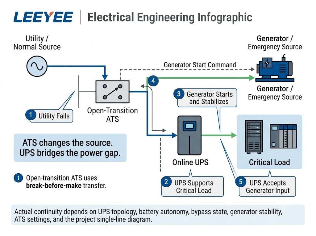
Table des matières
ATS vs UPS: What Does Each Device Actually Do?
IEC 60947-6-1:2026 covers transfer switching equipment used to transfer a load between power supply sources. Eaton likewise describes an ATS as a self-acting switching device that monitors the available sources and transfers the connected load according to its control logic. [1][2]
A UPS has a different job. It supports its downstream load when normal input power is disturbed or unavailable, according to the UPS topology, energy-storage system and operating state. It therefore provides a power bridge that an ordinary electromechanical ATS does not provide. [3]
| Equipment | Fonction principale | Stored-Energy Support | Role During Utility Failure |
|---|---|---|---|
| ATS | Transfers the load between acceptable power sources | Non | Selects the alternate source when transfer conditions are satisfied |
| UPS | Maintains suitable power to supported critical loads | Yes, according to UPS design | Supports the load while upstream power is unavailable |
| Générateur | Provides longer-duration standby power | Fuel-based energy source | Starts, stabilises and then supplies the standby system |
Signification de l'acheteur : specifying only “ATS + UPS” is not enough. The project must define which sources are being transferred, which loads require ride-through and what interruption those loads can tolerate.
Why Does an Open-Transition ATS Create a Power Gap?
Open transition is a break-before-make transfer method. The first source is disconnected before the second source is connected. Eaton describes this operating sequence in its ATS fundamentals guidance. [2]
That switching function is fundamentally different from stored-energy support. During the break in the upstream path, a sensitive electronic load needs another source of ride-through if even a short loss of supply is unacceptable.
Do not describe an ordinary open-transition ATS as a “zero-break” power device. If uninterrupted output is required at the critical load, continuity must be provided by the complete system architecture, such as an appropriately selected UPS, rather than by the open-transition ATS alone.
What Actually Happens After Utility Power Fails?
- The normal source becomes unacceptable. The ATS or source-monitoring system detects loss of utility power or another condition outside the configured source-acceptance range. [2]
- The UPS supports the critical load. If the UPS is operating through a topology and power path that provides stored-energy ride-through, the downstream critical load continues operating while upstream power is unavailable. [3]
- The standby generator starts. The generator needs time to start and establish usable output. [4]
- The emergency source reaches acceptable conditions. Voltage and frequency must satisfy the applicable transfer-control criteria before the normal transfer sequence proceeds. [2][4]
- The ATS transfers to the emergency source. With open transition, the normal source is disconnected before the generator source is connected. [2]
- The UPS accepts generator input. The UPS has its own acceptable input-voltage and frequency range. If generator output remains outside that range, the UPS can remain on battery. [5]
- The system enters recovery. The generator must remain stable while the UPS returns toward its intended operating state and battery recharge is managed.
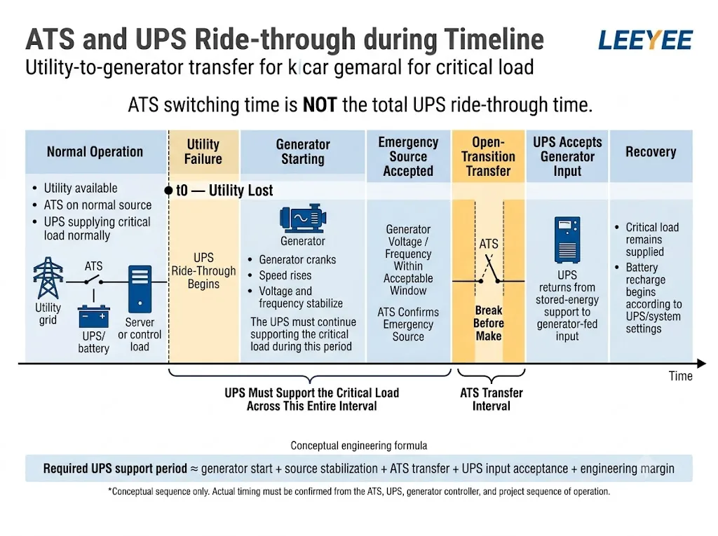
A generator-backed UPS may need to support the critical load from loss of the normal source until the generator has started, stabilised, passed ATS source-acceptance logic and become an acceptable UPS input. Actual timing must come from the selected ATS, generator controller, UPS documentation and project sequence of operation.
Should the ATS Be Installed Before or After the UPS?
Architecture 1: ATS Upstream of the UPS
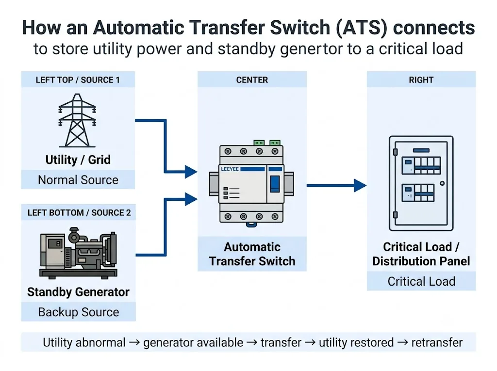
This is a common concept for generator-backed critical electronic loads. The ATS selects the long-duration upstream source while the downstream UPS bridges the source-change interval.
Architecture 2: Transfer Between Two UPS Outputs
This is a different architecture. The transfer device selects between two conditioned sources rather than between utility and generator inputs. Model-specific source synchronisation and transfer requirements must be confirmed. [6]
The question “Should the ATS be before or after the UPS?” cannot be answered safely from current rating alone. Review the single-line diagram, source arrangement, load type, redundancy concept and permitted interruption first.
Where Does the LEEYEE Compact ATS Fit?
The LEEYEE product shown below is a compact automatic transfer switch intended to switch between two suitable AC sources in low-voltage backup-power applications. In this article, it should be understood as the source-transfer element of the architecture—not as a UPS and not as a device that independently provides zero-interruption ride-through.
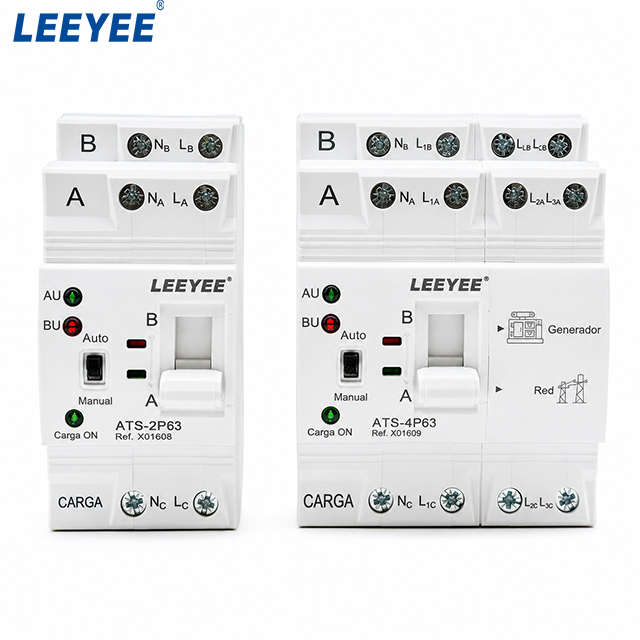
The ATS performs the automatic source change. The UPS provides the ride-through needed by sensitive loads while the upstream source is unavailable or changing.
LEEYEE's current standard compact ATS offering is based on ordinary open-transition source transfer. Closed-transition systems, bypass/isolation transfer equipment and maintenance-bypass assemblies are project-level extended solutions and must not be presented as standard built-in functions of the ordinary compact LEEYEE ATS.
Why Does Generator Stability Matter to the UPS?
A generator should not be treated as an acceptable UPS input simply because the engine has started.
Eaton notes that every UPS has an acceptable input voltage and frequency window. If generator output falls outside that window, the UPS can regard the generator as unstable and continue operating on battery. Generator sizing, governor performance and UPS topology also affect compatibility. [5]
If the generator is connected before it is sufficiently stable for the UPS and connected load, applying the load can further disturb voltage or frequency. Schneider Electric documents rack ATS scenarios in which unstable source conditions can contribute to repeated switching. [6] Actual behaviour depends on the selected equipment and project settings.
What Is the Real UPS Ride-Through Requirement?
Required UPS support period ≈ generator start + source stabilisation and acceptance + ATS transfer sequence + UPS input acceptance + appropriate project margin.
This is a conceptual relationship, not a universal sizing formula. No fixed seconds or milliseconds should be assumed without the selected generator controller, ATS controller, UPS specifications and project sequence of operation.
What Happens When Utility Power Returns?
Utility restoration does not necessarily mean that the ATS should immediately transfer back. The returning normal source first needs to satisfy the controller's return criteria and any configured retransfer delay.
Cummins describes transfer-switch control sequences in which a stable returning utility source initiates retransfer from generator back to utility. Generator shutdown can also include an unloaded cooldown period. Exact timing is controller- and project-specific. [4][7]
Why Must UPS Bypass Be Included in the Review?
A continuity study should not consider only normal UPS inverter operation. When the UPS is on static bypass, or when an external maintenance bypass isolates the UPS, the critical load can be more directly exposed to upstream source behaviour.
| Operating State | Power Path | Main Question |
|---|---|---|
| UPS inverter active | Load supplied through normal UPS conversion path | Can stored energy bridge the complete upstream event? |
| UPS static bypass | Load supplied through the bypass path | Will the upstream transfer reach the load? |
| Maintenance bypass active | UPS may be removed from the load path | Can the remaining system meet the continuity requirement? |
Does Closed Transition Remove the Need for a UPS?
No. Closed transition changes the transfer method between suitable sources. It does not provide stored-energy backup if both upstream sources are unavailable. A UPS can therefore still be required for critical loads. [1][2]
Which Status and Alarm Signals Matter?
| Statut | Pourquoi c'est important | Typical Source |
|---|---|---|
| Normal source available | Shows whether the preferred source satisfies the configured criteria | ATS / source monitor |
| Emergency source available | Shows whether the alternate source is ready | ATS / generator controller |
| Load on normal / emergency | Identifies the active source | ATS |
| UPS on battery | Shows stored-energy operation | UPS |
| UPS on bypass | Shows the normal inverter path is not active | UPS |
| Generator running / alarm | Shows standby-source status | Contrôleur de générateur |
Actual dry contacts, communication functions and alarms must be confirmed against the selected equipment. Do not assume every compact ATS provides every signal listed above.
How Should ATS + UPS Coordination Be Tested?
Individual generator, ATS and UPS tests do not by themselves prove that the complete system will coordinate correctly. Integrated testing should reproduce the relevant operating sequence under controlled project conditions.
- Simulate loss of normal power. Confirm source-failure detection.
- Verify UPS ride-through. Confirm the intended critical load remains supported.
- Verify generator startup. Confirm voltage and frequency become acceptable.
- Observe ATS transfer. Check the intended transfer sequence and watch for repeated source switching.
- Confirm UPS accepts generator input. Verify the UPS returns from stored-energy operation as intended.
- Verify alarms and remote status. Check required ATS, UPS and generator signals.
- Restore utility and test retransfer. Confirm transfer-back and generator cooldown behaviour follow the approved project sequence. [7]
Final test procedures, load levels and pass/fail criteria must follow the project specification, applicable standards and instructions for the selected ATS, UPS, generator and protection equipment.
Que doit-on confirmer avant de commander ?
Need to Confirm an ATS for a UPS-Backed System?
Send your single-line diagram, system voltage, load current, UPS topology, generator information and permitted interruption. LEEYEE can review whether a standard compact open-transition ATS matches the intended source-transfer function before model confirmation.
Questions fréquemment posées
Can an ATS replace a UPS?
No. The ATS transfers between power sources, while the UPS provides stored-energy support according to its topology. [1][3]
Can a UPS bridge an open-transition ATS transfer?
Yes, if the selected UPS topology, operating state and battery autonomy can support the load through the complete upstream interruption.
Should the ATS be before or after the UPS?
Utility-to-generator systems commonly place the ATS upstream of the UPS, but the final location must follow the project's single-line diagram and continuity objective.
Why might a UPS reject generator power?
A UPS has acceptable input voltage and frequency limits. Generator output outside that range can prevent the UPS from accepting the source. [5]
Does closed-transition ATS eliminate the need for a UPS?
No. Closed transition changes the source-transfer method but does not provide stored-energy backup if both sources fail. [1][2]
Is bypass isolation a standard feature of this LEEYEE compact ATS?
No. The standard compact LEEYEE ATS shown on this page is treated as an ordinary open-transition source-transfer device. Bypass-isolation and maintenance-bypass systems are separate engineered solutions.
Références
- International Electrotechnical Commission (IEC). IEC 60947-6-1:2026 — Low-voltage switchgear and controlgear — Part 6-1: Multiple function equipment — Transfer switching equipment. Page de publication IEC.
- Eaton. Fundamentals of Automatic Transfer Switches (ATS). Eaton ATS fundamentals.
- Schneider Electric. What is the transfer time of APC Smart-UPS and Symmetra Units? FAQ000268416. Schneider Electric UPS transfer-time FAQ.
- Cummins. GTEC Transfer Switch. Cummins transfer-switch information.
- Eaton. UPS for Generators: Six Considerations to Achieving Generator-UPS Harmony. Eaton generator-UPS guidance.
- Schneider Electric / APC. Common Rack Automatic Transfer Switch Scenarios and Questions. FA156201. Schneider Electric Rack ATS technical FAQ.
- Cummins Power Generation. Transfer Switch Application Manual. Cummins Transfer Switch Application Manual.
