
An ATS datasheet is not just a list of ratings. For a distributor, panel builder, generator-set integrator, electrical contractor or OEM buyer, it is a project-compatibility document. The correct way to read it is to compare the automatic transfer switch specifications with the single-line diagram, load, upstream protection, control requirements and project specification before the purchase order is confirmed.
Table of Contents
Quick Answer: What Should You Check First?
Start with the actual electrical system. Verify rated operational current, rated operational voltage, frequency and pole configuration first. Then review utilization category, PC or CB classification, short-circuit data, transition method, timing, control and status interfaces, terminal information and environmental limits. Finally, compare the exact ATS configuration with the single-line diagram, project specification and applicable certificate or technical-document scope. [1][2]
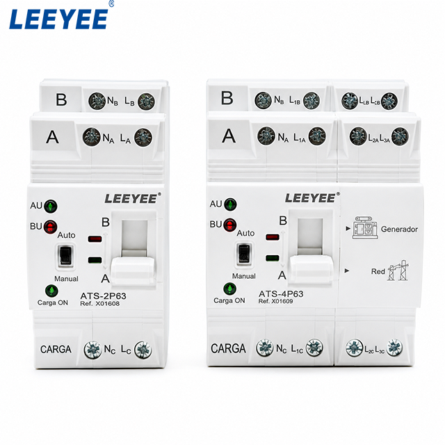

1. Start With the Project, Not the ATS Model Number
Before comparing ATS models, identify where the transfer switch sits in the electrical system. Confirm the normal source, emergency source, load, system voltage, frequency, phase arrangement, neutral arrangement and upstream protective devices.
A datasheet describes what a device is designed and rated to do. The single-line diagram and project specification describe what the installation requires. A technically suitable purchase requires those two sides to match.
2. Rated Current: Check the ATS Feeder, Not Just the Generator Nameplate
Rated operational current is usually one of the first values buyers notice. It should be compared with the design current of the circuit that actually passes through the ATS, not selected only from the equipment name or generator rating.
The ATS may serve only part of the generator capacity. The downstream load can also contain motors, transformers, UPS equipment or mixed loads that affect the required switching duty.
Read current together with voltage and utilization category rather than as an isolated ampere number.
| Datasheet field | What it means | What the buyer should compare |
|---|---|---|
| Rated operational current | Declared current capability for specified operating conditions | Design current of the ATS feeder |
| Rated operational voltage | Voltage associated with the declared operating performance | Normal and emergency source voltage |
| Utilization category | Declared switching-duty category | Actual load characteristics |
ABB IEC transfer-switch data illustrates why these fields belong together: current ratings are published together with voltage and utilization-category information rather than as a single universal ampere value. [2]
3. Read 2P, 3P and 4P Together With the Neutral Design
Pole count and phase count are related, but they are not identical concepts. A three-phase installation can use a 3-pole or 4-pole transfer arrangement depending on whether the neutral is required to be switched.
Eaton notes that a three-phase transfer switch can use a fully rated fourth pole when neutral switching is required, and that switched-neutral arrangements are commonly associated with separately derived sources. [3]
4. Ue, Ui and Uimp Are Three Different Voltage Ratings
One of the easiest mistakes when reading an ATS datasheet is treating every voltage number as the operating voltage.
| Symbol | Datasheet meaning | Buyer interpretation |
|---|---|---|
| Ue | Rated operational voltage | Compare with the real system operating voltage |
| Ui | Rated insulation voltage | Relates to insulation design; it is not the normal operating voltage |
| Uimp | Rated impulse withstand voltage | Relates to specified impulse withstand capability, not continuous operation |
ABB TruONE technical data, for example, lists Ue, Ui and Uimp as separate specifications. This makes an important procurement point: a high Ui or Uimp value does not mean the ATS is intended to operate continuously at that voltage. [2]
5. Frequency and Voltage Must Match the Actual Sources
Check the operating voltage and frequency of both sources. A transfer switch used between utility and generator supplies must be compatible with the electrical conditions the controller and switching mechanism are expected to see.
Do not assume that every value in a multi-voltage datasheet applies identically at every voltage. Current ratings, utilization categories and short-circuit performance may be declared under defined voltage conditions. [2]
6. Utilization Category Tells You the Switching Duty Behind the Current Rating
IEC-type ATS datasheets can show utilization categories such as AC-31 or AC-33 variants. These categories help identify the switching duty for which performance is declared.
ABB technical tables publish operational-current and switching data by utilization category, showing why two products with the same nominal ampere number should not be compared until the applicable duty category is checked. [2]
7. PC Class and CB Class Affect the Protection Review
ATS classification affects how the transfer equipment fits into the protection scheme. IEC 60947-6-1 includes transfer switching equipment requirements and also addresses performance requirements for CB-type TSE in alignment with circuit-breaker requirements. [1]
For PC-class equipment, the manufacturer's declared conditional short-circuit and withstand data should be read together with the upstream protective-device information. ABB's IEC Class PC technical tables, for example, list conditional short-circuit current, corresponding fuses or circuit breakers and short-time withstand current as separate parameters. [2]
8. Short-Circuit Capability Cannot Be Judged by One kA Number
Short-circuit data is one of the most important—and most easily misread—parts of an ATS datasheet.
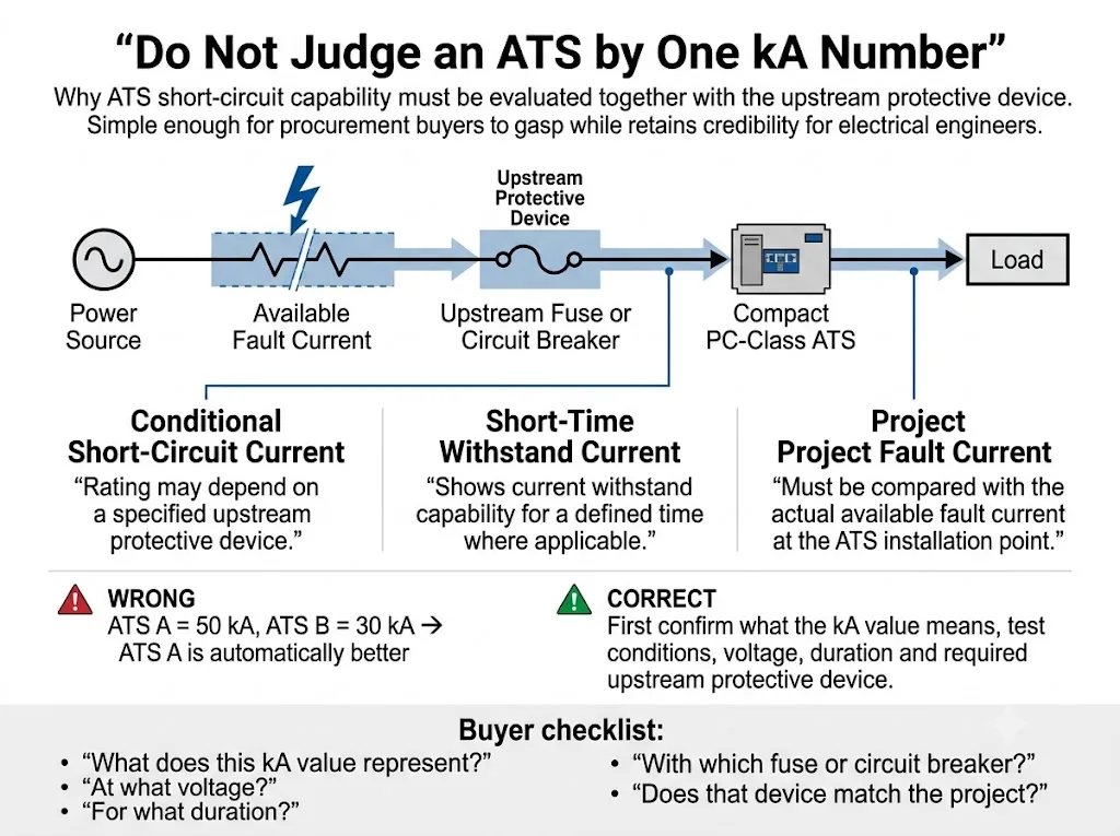
An IEC datasheet can include conditional short-circuit current Iq, short-time withstand current Icw and making-capacity data. These values describe different characteristics and must not be treated as interchangeable. ABB technical data publishes Iq, Icw and Icm separately and associates conditional ratings with specified protective devices. [2]
The same coordination principle is important in other standards systems. Eaton explains that transfer-switch withstand and closing ratings must be considered together with available fault current and the overcurrent protective device that clears the fault. [4]
9. Transfer Time, Operation Time and Controller Delay Are Not the Same Parameter
Datasheets can list contact transfer time, operating transfer time and controller delay settings separately. The exact terminology varies by manufacturer, so the definition attached to each value matters.
ABB technical data, for example, lists contact transfer time and operating transfer time separately. [2] In a generator-backed system, the complete interruption seen by the load can also include source-failure detection, generator starting, voltage and frequency acceptance, intentional delays and mechanical transfer.
Normal source fails → controller confirms the abnormal condition → generator start command is issued where applicable → emergency source reaches acceptable conditions → transfer is initiated → switching mechanism changes source
A small mechanical or contact-transfer-time number therefore should not automatically be presented as the total time from utility failure to restored generator supply.
What does open transition mean?
Open transition is a break-before-make transfer: the ATS disconnects from one source before connecting the load to the other. Eaton describes open transition using this same break-before-make principle. [5]
IEC 60947-6-1:2026 separately includes requirements for bypass/isolation transfer switch equipment in Annex C and closed-transition ATSE in Annex D. [1] Those functions therefore should not be assumed from a standard compact open-transition ATS datasheet.
10. Control Voltage, Sensing Voltage and Remote Signals Need Model-Specific Verification
The power-circuit voltage does not tell you everything about the ATS controller. Depending on the product design, controller supply, actuator supply and source-sensing ranges can be specified separately.
Check how the selected ATS monitors the normal and emergency sources and whether any external control supply is required. If the datasheet does not answer this clearly, request the model-specific wiring diagram or installation manual before production.
Generator-set and BMS integration also require a separate review of dry contacts and auxiliary outputs. Typical project points can include generator start, Normal Available, Emergency Available, Load to Normal, Load to Emergency, operating mode and fault indication.
11. Power Terminals and Control Terminals Answer Different Questions
A wiring diagram and a terminal schedule are not the same thing. The wiring diagram explains electrical relationships. Terminal information tells the panel builder what can physically and electrically be connected to the ATS.
| Terminal information | What to check | Why procurement cares |
|---|---|---|
| Main power terminals | Source, load and neutral identification | Prevents panel layout and connection mistakes |
| Conductor range | Permitted cable or busbar arrangement | Confirms connection compatibility |
| Bolt / terminal size | Mechanical connection specification | Affects lugs, busbars and assembly preparation |
| Tightening torque | Manufacturer-specified assembly torque | Must be followed during installation |
| Control terminals | Start, status, alarm and auxiliary functions | Determines generator, PLC and BMS integration |
Real ATS technical documentation can include conductor cross-section, terminal bolt size and tightening torque alongside electrical ratings. ABB's TruONE data is one example. [2] These values are model-specific and should never be copied from another ATS family.
12. Do Not Ignore Installation, Environmental and Durability Data
Some datasheet fields do not determine the first model shortlist, but they can decide whether the selected ATS can actually be built into the panel and accepted for the site.
ABB ATS technical documentation illustrates this broader datasheet structure by publishing dimensions, weight, mechanical endurance and connection information in addition to core electrical ratings. [2]
13. Datasheet, Certificate and Test Report Are Not the Same Evidence
Buyers often receive several technical documents with an ATS quotation. They should not be treated as interchangeable.
14. How Should IEC 60947-6-1 Be Read on an ATS Datasheet?
IEC 60947-6-1:2026 is the current fourth edition of the IEC standard for transfer switching equipment. It was published on 2 April 2026 and replaced the 2021 edition. Its scope covers manually operated, remotely operated and automatic transfer switching equipment, and the 2026 edition adds or clarifies dedicated requirements for bypass/isolation equipment, closed-transition ATSE and stand-alone ATS controllers. [1]
Seeing “IEC 60947-6-1” on a catalogue is therefore an important technical reference, but it is not the end of document verification.
If the project requires a particular national adoption, certification scheme or market approval, confirm that requirement separately. A general reference to an IEC standard should not be treated as proof of every destination-market approval.
15. Compare the Datasheet With the Single-Line Diagram and Project Specification
This is the step that converts datasheet reading into real engineering selection. Put the ATS datasheet beside the approved single-line diagram and check the circuit from both sources through the ATS to the load.

The most valuable column below is the final one: these are mismatches that can survive a basic current-and-voltage check.
| Project information | ATS datasheet check | Mismatch to catch |
|---|---|---|
| Normal / emergency source | Ue, frequency, source sensing | Incorrect voltage or sensing arrangement |
| ATS feeder current | Rated operational current | ATS selected only from generator size |
| Neutral arrangement | 2P / 3P / 4P | Wrong switched-neutral assumption |
| Upstream breaker / fuse | Iq / Icw / applicable short-circuit data | kA value used without its protection condition |
| Load characteristics | Utilization category | Same current compared under different duty |
| Generator controller | Start-contact interface | Required dry-contact logic unavailable |
| BMS / PLC | Auxiliary and remote outputs | Required feedback signals not provided |
| Panel design | Dimensions and terminals | Device fits electrically but not physically |
Procurement conclusion: the datasheet should not be approved in isolation. It must be cross-checked against the electrical design and the written project requirements.
16. What Must Be Reconfirmed Before Ordering?
A useful RFQ gives the supplier enough information to confirm the configuration rather than forcing both sides to infer requirements from a model number.
Need a Model Check Before You Place the ATS Order?
Send the single-line diagram, system voltage, design current, required poles, upstream protective device, transition requirement and control-signal list. LEEYEE can review whether the requested compact open-transition ATS configuration fits the intended product and project scope.
Frequently Asked Questions
Is rated current enough to choose an ATS?
No. Rated current should be checked together with voltage, utilization category, poles, short-circuit requirements, upstream protection, load characteristics and the actual circuit served by the ATS.
What is the difference between Ue, Ui and Uimp on an ATS datasheet?
Ue is the rated operational voltage. Ui is the rated insulation voltage. Uimp is the rated impulse withstand voltage. They describe different characteristics and should not be used interchangeably. [2]
Can I compare two ATS products only by their kA rating?
No. First identify what each short-circuit value represents, the applicable voltage and duration, and whether the rating depends on a specified upstream protective device. [2][4]
Does every three-phase four-wire system require a 4P ATS?
No. The key issue is whether the neutral must be switched. Review the grounding and bonding arrangement and the approved project design before choosing the pole configuration. [3]
Is ATS transfer time the same as generator restoration time?
Not necessarily. Generator restoration can also include failure detection, intentional delays, generator starting and source-acceptance logic. Read the exact definition of every timing value in the selected controller documentation. [2]
Are the power-terminal schedule and control-terminal diagram the same thing?
No. Power-terminal data can define conductor size, bolt size, torque and main-circuit connections, while control documentation defines sensing, generator-start, status, alarm and auxiliary interfaces.
Does IEC 60947-6-1 on a brochure prove that my exact ATS model is covered?
Do not assume so. Check the exact model or product range covered by the applicable declaration, certificate or report and compare that scope with the configuration being ordered.
What should I send a supplier for accurate ATS model confirmation?
Send the single-line diagram, source arrangement, voltage, frequency, design current, poles, load information, upstream protective device, available fault-current information, transition requirement, control signals, required documents and relevant installation conditions.
References
- International Electrotechnical Commission (IEC). IEC 60947-6-1:2026 — Low-voltage switchgear and controlgear — Part 6-1: Multiple function equipment — Transfer switching equipment. Edition 4.0, published 2 April 2026. IEC publication page.
- ABB. TruONE ATS — Automatic Transfer Switches, Technical Data according to IEC 60947-6-1. Manufacturer technical data includes Ue, Ui, Uimp, frequency, poles, utilization category, Iq, Icw, Icm, transfer-time data, mechanical endurance, conductor cross-section, terminal bolt size, tightening torque, dimensions and weight. ABB technical catalogue.
- Eaton. Low-voltage Contactor Type Transfer Switches Design Guide. Guidance includes switched-neutral application principles for three-phase and single-phase transfer systems. Eaton design guide.
- Eaton. Selecting Protective Devices Handbook. Transfer-switch guidance explains the relationship between short-circuit withstand/closing ratings, available fault current and protective devices. Eaton protective-device handbook.
- Eaton. Automatic Transfer Switch Fundamentals. Technical guidance covers source monitoring, open and closed transition, switched-neutral arrangements, transfer mechanisms and transfer-switch ratings. Eaton ATS fundamentals.