
Panduan Rekayasa SPD, Inspeksi Lokasi, dan Pemilihan OEM
Pembacaan resistansi tanah yang rendah sangat membantu, tetapi itu sendiri tidak membuktikan bahwa SPD memiliki jalur arus lonjakan yang efektif. Insinyur juga harus memeriksa kontinuitas PE, impedansi transien, pengikatan equipotential, jenis sistem pembumian, dan hubungan antara SPD dan peralatan yang dilindungi.
Daftar Isi
Jawaban Cepat
Resistansi grounding yang tinggi dapat mengurangi kinerja perlindungan yang terpasang dari SPD dengan meningkatkan tegangan transien di sepanjang jalur tanah, PE, dan pengikatan. Namun, tidak ada persyaratan universal 1Ω, 5Ω, atau 10Ω untuk setiap instalasi SPD. Standar proyek yang berlaku, sistem grounding, pengikatan potensial yang sama, dan jalur arus lonjakan yang lengkap semua harus diperiksa.
SPD dapat beroperasi secara normal sementara peralatan yang dilindungi masih mengalami tegangan berlebih yang disebabkan oleh impedansi konduktor atau perbedaan potensial transien antara referensi grounding yang terpisah.
Perlindungan SPD yang baik memerlukan jalur arus yang terkoordinasi, pendek, dan impedansi rendah — bukan hanya pembacaan yang rendah pada penguji resistansi tanah.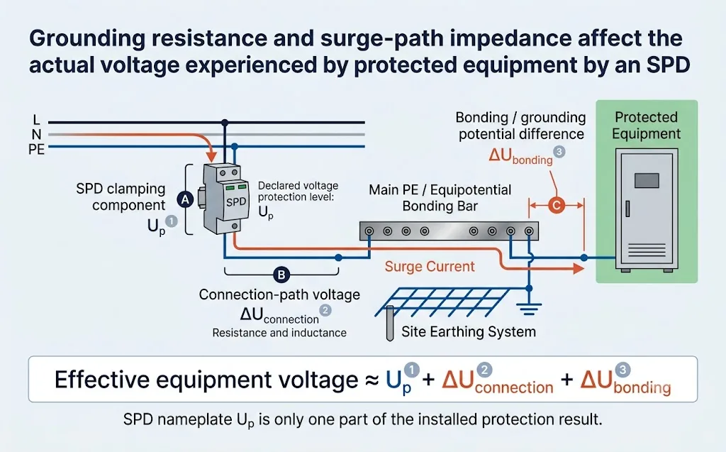
Bisakah SPD Bekerja Tanpa Grounding?
Jawaban yang secara teknis benar adalah: itu tergantung pada mode perlindungan SPD dan desain sistem.
SPD membatasi tegangan antara konduktor yang terhubung ke terminalnya. Mode perlindungan antara fase dan netral dapat membatasi lonjakan mode diferensial tanpa menggunakan elektroda tanah lokal sebagai jalur arus langsung. Sebaliknya, L–PE, N–PE, positif–PE, negatif–PE, dan banyak mode perlindungan sinyal-ke-tanah sangat bergantung pada sambungan PE atau pengikatan potensial yang benar.
| Mode Perlindungan | Ketergantungan pada PE atau Tanah | Makna Teknik |
|---|---|---|
| L–N atau kutub-ke-kutub | Dapat membatasi tegangan mode diferensial antara dua konduktor pembawa arus yang terhubung. | Ini tidak membuktikan bahwa perlindungan mode umum atau instalasi lengkap aman tanpa PE. |
| L–PE atau kutub-ke-PE | Memerlukan jalur tanah pelindung atau pengikatan potensial yang sesuai. | Sambungan PE yang hilang, longgar, atau impedansi tinggi dapat secara serius mengurangi hasil perlindungan yang terpasang. |
| N–PE | Tergantung pada jalur perlindungan netral-ke-tanah yang didefinisikan oleh sistem penyaluran tanah dan topologi SPD. | Sangat penting dalam banyak pengaturan sistem TT 1+1 dan 3+1. |
| Sinyal-ke-tanah atau pelindung | Memerlukan pengikatan referensi yang terkoordinasi antara SPD sinyal, perangkat, dan layar kabel. | Referensi tanah yang terpisah dapat memaksa arus melalui port komunikasi atau isolasi peralatan. |
Bahkan di mana satu mode perlindungan diferensial dapat mengalir, instalasi mungkin masih kekurangan perlindungan mode umum yang aman, pengikatan pelindung, atau koneksi yang diperlukan oleh produsen SPD. Selalu ikuti diagram pengkabelan dan desain listrik yang berlaku.
Mengapa Grounding Penting untuk SPD?
Ketika sebuah transien melebihi ambang batas operasi SPD, SPD berubah menjadi keadaan konduktif dan menciptakan jalur impedansi lebih rendah antara terminal yang terhubung. Arus lonjakan kemudian mengikuti jalur sistem listrik melalui konduktor hidup, netral, PE, konduktor pengikat, layar kabel, logam struktural, atau sistem terminasi tanah.
Tujuannya tidak sekadar untuk “mengirim semua energi lonjakan ke tanah.” Tujuan yang lebih penting adalah menjaga peralatan yang terhubung dan sistem konduktif pada potensi relatif yang terkontrol selama peristiwa lonjakan.
Empat Istilah Grounding yang Tidak Boleh Diperlakukan Sebagai Hal yang Sama
Resistansi Elektrode Tanah
Resistansi yang diukur antara sistem elektrode tanah dan tanah sekitarnya di bawah metode uji yang dipilih.
Kontektivitas PE
Apakah terminal tanah SPD, kabinet, batang PE, dan terminal pembumian utama memiliki sambungan metalik yang berkesinambungan dan dapat diandalkan secara mekanis.
Impedansi Jalur Lonjakan
Tahanan transien yang dihasilkan oleh resistansi, induktansi, geometri penghantar, sambungan, pengaturan, dan jaringan ikatan yang lebih luas.
Ikatan Equipotential
Sambungan terkoordinasi dari sistem konduktif untuk mengurangi perbedaan tegangan berbahaya selama peristiwa kesalahan, petir, dan lonjakan.
Sebuah lokasi dapat menunjukkan resistansi elektrode tanah yang relatif rendah tetapi masih memiliki kinerja SPD yang buruk karena rute PE yang panjang, sambungan yang terkorosi, jaringan tanah yang terisolasi, atau jarak yang besar antara titik referensi SPD dan peralatan yang dilindungi.
Apa yang Terjadi Ketika Resistansi Grounding atau Impedansi Jalur Terlalu Tinggi?
| Masalah Potensial | Apa yang Terjadi Selama Lonjakan | Konsekuensi Proyek yang Mungkin |
|---|---|---|
| Tegangan jalur yang lebih tinggi | Arus lonjakan yang melewati resistansi dan induktansi menghasilkan tegangan transien tambahan sepanjang jalur arus. | Peralatan mungkin mengalami tegangan yang lebih tinggi dari yang disarankan oleh Up yang diumumkan SPD saja. |
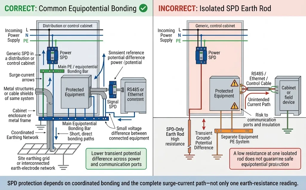
| Kenaikan potensi tanah | Arus yang masuk ke sistem terminasi tanah meningkatkan potensi lokalnya relatif terhadap titik referensi lainnya. | Arus dapat mengalir melalui kabel data, layar, pipa, atau jaringan grounding struktur lainnya. |
| Referensi peralatan yang berbeda | SPD dan peralatan yang dilindungi tidak naik ke potensi transien yang sama pada saat yang sama. | Tegangan yang merusak dapat muncul di terminal peralatan, port komunikasi, atau isolasi. |
| Jalur arus yang tidak diinginkan | Lonjakan menggunakan jalur paralel dengan impedansi transien yang lebih rendah daripada rute pengikatan yang dimaksudkan. | Pelindung kabel, PLC I/O, RS485, port komunikasi Ethernet atau inverter dapat membawa sebagian dari arus. |
| Kegagalan koordinasi perlindungan | SPD daya dan sinyal merujuk pada titik bumi atau pengikatan yang berbeda. | Sirkuit yang berbeda yang terhubung ke perangkat yang sama dapat dijepit ke potensi transien yang berbeda. |
Masalah utama biasanya bukanlah operasi SPD internal yang lebih lambat. Masalahnya adalah tegangan tambahan di luar SPD, sepanjang konduktor dan antara referensi grounding yang berbeda.
Resistansi Grounding vs Impedansi Jalur Lonjakan
Tes resistansi tanah yang normal memberikan informasi berguna tentang sistem elektroda tanah di bawah kondisi pengujian yang dipilih. Namun, arus petir dan lonjakan dapat meningkat sangat cepat. Selama peristiwa transien ini, induktansi konduktor, bongkok, loop, jarak, dan geometri pengikatan dapat menjadi bagian utama dari impedansi jalur arus.
Jaga loop arus lonjakan tetap kompak, gunakan titik pemosisian equipotential yang dimaksud, hindari sistem referensi yang tidak terkoordinasi dan lindungi semua layanan konduktif yang masuk ke zona yang dilindungi.
Apakah SPD Memerlukan Resistansi Grounding 1Ω, 5Ω, atau 10Ω?
Tidak ada batas resistansi SPD saja yang berlaku untuk setiap instalasi. Persyaratan numerik mungkin berasal dari kode listrik nasional, desain perlindungan petir, aturan utilitas, spesifikasi operator telekomunikasi, pemilik proyek, penjamin atau produsen peralatan.
Hasil yang diukur harus dibandingkan dengan dokumen pengatur yang jelas teridentifikasi - bukan disalin dari artikel online yang umum.
| Situasi Proyek | Cara Memperlakukan Nilai Ohm | Apa yang Harus Juga Diverifikasi |
|---|---|---|
| Bangunan LV umum | Ikuti persyaratan keselamatan listrik dan pembumian lokal. Jangan membuat batasan SPD terpisah tanpa dasar yang jelas. | Terminal pembumian utama, kontinuitas PE, ikatan (bonding), lokasi SPD, mode perlindungan, dan jalur konduktor. |
| Pembangkit listrik PV lapangan terbuka | Gunakan desain perlindungan petir dan PV proyek, termasuk kriteria penerimaan kisi bumi yang ditentukan. | Jaringan bumi jala, struktur yang saling terhubung, stasiun inverter, rute kabel, korosi, dan kondisi musiman. |
| Situs telekomunikasi atau menara | Gunakan spesifikasi pembumian operator dan desain perlindungan petir situs. | Menara, kabinet, SPD AC, SPD DC, SPD data, pengumpan antena, layar, dan batang bumi umum. |
| Fasilitas kritis | Perlakukan nilai tersebut sebagai persyaratan desain sistem yang lengkap, bukan parameter produk SPD universal. | Geometri kisi bumi, tegangan sentuh dan langkah, arus gangguan, dan koordinasi perlindungan. |
| Papan distribusi OEM | Pembuat panel tidak dapat menentukan resistansi bumi situs akhir hanya dari model SPD atau gambar panel saja. | Terminal PE yang benar, persyaratan konduktor, diagram pemasangan, dan petunjuk komisioning situs. |
Situs mungkin menunjukkan hasil elektroda yang memuaskan sementara SPD tersambung melalui konduktor panjang, sambungan berkarat, atau referensi terpisah dari peralatan yang dilindungi. Jalur lengkap harus diperiksa.
Bagaimana Resistansi Grounding SPD Harus Diukur?
Tidak ada instrumen khusus yang mengukur "resistansi pembumian SPD" universal. Metode pengujian bergantung pada apakah insinyur perlu menilai elektroda bumi, satu cabang jaringan pembumian paralel, loop bumi lengkap, atau hanya kontinuitas konduktor PE lokal.
| Metode Uji | Penggunaan Umum | Batasan Utama | Apa yang Harus Diminta Pembeli |
|---|---|---|---|
| 3-titik fall-of-potential | Menguji elektroda bumi atau sistem elektroda menggunakan pancang uji arus dan potensial terpisah. | Memerlukan jarak uji yang cukup dan akses tanah yang sesuai. Jalur paralel mungkin perlu dipertimbangkan atau diisolasi. | Elektroda yang diuji, posisi probe, kurva uji atau titik validasi, hasil terukur, dan kondisi situs. |
| Tes bumi selektif | Mengukur satu bagian dari sistem pembumian paralel menggunakan pancang uji ditambah klem arus. | Penguji harus memahami jaringan paralel dan menempatkan klem pada konduktor yang benar. | Cabang yang diukur, diagram jaringan, posisi klem, tata letak pancang uji, dan hasilnya. |
| Tes klem atau tanpa pancang | Pengujian cepat di mana beberapa jalur pembumian menciptakan loop konduktif lengkap. | Ini tidak cocok untuk setiap elektroda tunggal yang diisolasi karena diperlukan loop pengembalian yang valid. | Konfirmasi bahwa loop paralel tertutup ada dan penjelasan mengenai resistansi apa yang diukur instrumen. |
| Tes kontinuitas PE | Memeriksa apakah terminal bumi SPD tersambung terus-menerus ke batang PE atau titik pengikatan utama. | Tidak mengukur resistansi elektroda bumi atau membuktikan impedansi frekuensi tinggi yang rendah. | Titik uji, identifikasi konduktor, kontinuitas terukur, dan inspeksi terminal serta sambungan. |
| Inspeksi visual dan torsi | Mendeteksi terminal longgar, korosi, konduktor putus, loop tajam, dan koneksi referensi yang salah. | Tidak dapat menggantikan pengukuran elektrikal. | Foto, ukuran konduktor, rute, kondisi terminal, dan catatan komisioning. |
Catatan Pengukuran Minimum untuk EPC atau Tim Pemeliharaan
- Elektroda, kisi, atau konduktor yang diuji secara tepat
- Model instrumen dan status kalibrasi
- Metode uji yang digunakan
- Posisi probe atau klem
- Nilai dan satuan yang diukur
- Apakah jalur paralel terhubung
- Kondisi tanah dan cuaca
- Tanggal pengujian dan kondisi musiman
- Batas penerimaan yang berlaku
- Nama atau peran penguji yang berkualifikasi
- Foto titik koneksi
- Tindakan korektif dan hasil pengujian ulang
Multimeter dapat membantu mengidentifikasi koneksi terbuka atau koneksi yang jelas buruk, tetapi tidak dapat menggantikan penguji pembumian yang tepat atau menunjukkan impedansi transien lengkap dari jalur arus SPD.
Apa yang Harus Dilakukan Jika Resistansi Grounding Terlalu Tinggi?
Tindakan korektif harus mengatasi penyebab hasil tersebut dan sistem perlindungan secara menyeluruh. Mengganti SPD dengan model kA yang lebih tinggi tidak memperbaiki pembumian atau jaringan pengikatan yang buruk.
- Verifikasi pengukuran Pastikan metodenya sesuai dengan konfigurasi elektroda dan bahwa jalur paralel, jarak probe, serta kondisi musiman telah dipertimbangkan.
- Periksa koneksi yang dapat diakses Periksa klem, lug, bar, titik akses sambungan yang terkubur, dan konduktor terhadap kelonggaran, korosi, kerusakan, kelembapan, atau kerusakan mekanis.
- Perbaiki sambungan yang cacat Pulihkan jalur konduktif yang dirancang menggunakan material, metode koneksi, dan pelindung korosi yang sesuai.
- Tinjau desain elektroda Insinyur yang berkualifikasi mungkin perlu memodifikasi kedalaman, jarak, jumlah elektroda, konduktor cincin, atau desain jaringan pembumian lokasi.
- Interkoneksi sistem jika diperlukan Hindari penambahan batang pembumian khusus SPD yang tidak terikat. Struktur dan layanan terpisah harus dikoordinasikan sesuai dengan desain proyek.
- Tingkatkan koneksi SPD lokal Jaga agar koneksi ke konduktor aktif dan bar PE atau pengikat tetap pendek, langsung, dan bebas dari loop yang tidak perlu.
- Koordinasikan perlindungan daya dan sinyal Periksa AC, DC, RS485, Ethernet, koaksial, pelindung, dan layanan logam agar satu jalur yang tidak terlindungi tidak menjembatani dua potensi transien.
- Uji ulang dan dokumentasikan Catat tindakan korektif, ulangi pengujian yang sesuai, dan perbarui gambar as-built serta file pemeliharaan.
Elektroda terisolasi yang tidak terkoordinasi dapat menciptakan perbedaan tegangan transien yang berbahaya antara SPD, PE peralatan, dan sistem komunikasi. Nilai rendah pada satu batang terisolasi tidak menjamin perlindungan ekipotensial yang aman.
Bagaimana Jenis Sistem Pembumian Mengubah Penilaian SPD
| Sistem | Jalur SPD yang Relevan | Pemeriksaan Pembumian dan Pengikatan |
|---|---|---|
| TN-S | Jalur L–PE, N–PE, atau L–N tergantung pada topologi SPD. | Konfirmasikan bahwa SPD terhubung ke bar PE panel dan jaringan PE logam umum melalui jalur yang pendek dan langsung. Hasil elektroda lokal saja mungkin tidak menggambarkan jalur ini. |
| TT | Umumnya perlindungan L–N ditambah jalur N–PE terkoordinasi dalam susunan 1+1 atau 3+1. | Konfirmasikan elektroda pembumian instalasi, susunan RCD, mode perlindungan N–PE, dan persyaratan lokal. Jangan membuat ikatan N–PE hilir yang tidak sah. |
| TN-C-S | Tergantung pada apakah SPD diposisikan sebelum atau sesudah pemisahan PEN. | Identifikasi titik pisah PEN. N dan PE hilir harus diperlakukan sesuai dengan desain instalasi dan aturan lokal. |
| TN-C | Konduktor fase dapat dilindungi ke PEN pada titik yang berlaku. | Konfirmasikan posisi instalasi dan susunan konduktor yang diizinkan. Jangan berasumsi bahwa terdapat N dan PE terpisah pada titik tersebut. |
| IT | Susunan fase-ke-bumi atau kutub-ke-bumi khusus proyek. | Konfirmasikan tegangan sistem ke bumi, perilaku kesalahan pertama, pemantauan isolasi, persyaratan peralatan, dan Uc SPD yang sesuai. |
Untuk panduan topologi tambahan, tinjau Panduan Diagram Pemasangan SPD Tiga Fasa dan Panduan SPD 3P+N vs SPD 4P .
Pemeriksaan Grounding untuk Proyek Solar, Telekomunikasi, dan Industri
Sistem PV Surya
- Konfirmasikan apakah sistem proteksi petir eksternal tersedia.
- Periksa pengikatan rangka modul dan rel pemasangan.
- Identifikasi jaringan pembumian susunan (array), inverter, dan bangunan.
- Tinjau titik masuk kabel DC, AC, dan komunikasi.
- Periksa korosi dan variasi tanah musiman.
- Konfirmasikan apakah struktur terpisah saling terhubung dengan benar.
Telekomunikasi dan Stasiun Pangkalan
- Koordinasikan perlindungan AC, −48V DC, data, dan jalur antena.
- Periksa bonding menara, kabinet, dan layar pengumpan (feeder-screen).
- Hubungkan SPD daya dan sinyal ke referensi yang dituju.
- Periksa sambungan eksternal untuk mendeteksi korosi dan rembesan air.
- Tinjau tingkat bonding dalam dan luar ruangan yang terpisah.
- Ikuti spesifikasi pentanahan operator telekomunikasi.
Kabinet Industri dan Luar Ruangan
- Periksa rute kabel daya masuk dan kabel sinyal lapangan.
- Lakukan bonding pada enklosur, pintu, dan pelat gland jika diperlukan.
- Pisahkan konduktor yang terlindungi dan tidak terlindungi.
- Tinjau antarmuka PLC, VFD, RS485, dan Ethernet.
- Periksa torsi terminal, lug, dan jalur konduktor.
- Identifikasi struktur di sekitar yang menggunakan referensi bumi lain.
Ketika dua bangunan, susunan PV, kabinet, atau instrumen lapangan dihubungkan oleh kabel tembaga tetapi menggunakan jaringan arde yang terpisah, petir dapat menciptakan perbedaan potensial yang besar di antara keduanya. Perlindungan daya dan sinyal harus dikoordinasikan pada batas zona yang relevan.
Informasi yang Harus Diberikan Pembeli Sebelum Memesan SPD
Pemasok SPD tidak dapat menentukan desain pentanahan yang lengkap hanya dari tegangan sistem dan peringkat kA saja. EPC, pembuat panel, dan pembeli proyek harus memberikan informasi lokasi di bawah ini sebelum konfirmasi produk akhir.
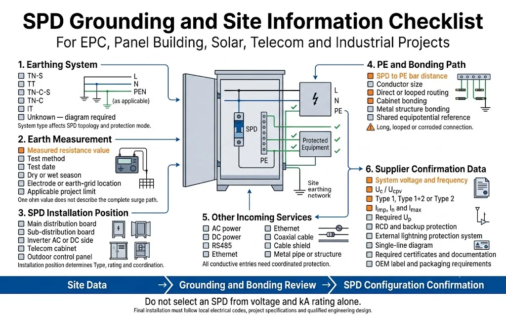
- Negara dan standar proyek yang berlaku
- Tegangan dan frekuensi sistem
- Persyaratan perlindungan AC, DC, sinyal, atau gabungan
- Sistem TN-S, TT, TN-C-S, TN-C, atau IT
- Diagram satu baris yang menunjukkan N, PE, dan PEN
- Posisi pemasangan SPD
- Papan utama, sub-papan, combiner box, atau kabinet kontrol
- Sistem proteksi petir eksternal: ya atau tidak
- Sumber masuk di atas kepala atau bawah tanah
- Resistansi arde yang terukur dan metode pengujian
- Tanggal pengukuran dan kondisi musiman
- Jumlah dan lokasi elektroda atau grid
- Apakah struktur menggunakan jaringan arde terpisah
- Jarak antara SPD dan peralatan yang dilindungi
- Jarak dari SPD ke PE atau batang bonding
- Tipe 1, Tipe 1+2, atau Tipe 2 yang diperlukan
- Uc, Ucpv, Up, In, Imax, dan Iimp yang diperlukan
- Pengaturan RCD dan perlindungan cadangan
- Titik masuk kabel daya dan komunikasi
- Persyaratan kontak sinyal jarak jauh
- Sertifikat dan dokumentasi yang diperlukan
- Persyaratan label OEM, warna, dan pengemasan
“Kami memerlukan SPD untuk kabinet distribusi luar ruangan tiga fase 400V. Sistem pentanahan: TT. Resistansi arde yang terukur adalah 12Ω menggunakan metode fall-of-potential. Lokasi tersebut memiliki sistem LPS eksternal dan RCD. Sambungan dari SPD ke batang PE sekitar 300mm. Harap konfirmasikan konfigurasi Tipe 1+2 yang sesuai, mode perlindungan N–PE, Uc, Iimp, perlindungan cadangan, dan diagram pengabelan.”
Kesalahan Umum Grounding SPD
| Kesalahan | Mengapa Hal Ini Berisiko | Pendekatan yang Lebih Baik |
|---|---|---|
| Menggunakan batang arde terisolasi hanya untuk SPD | Hal ini dapat menciptakan perbedaan tegangan yang besar antara SPD, PE peralatan, dan layanan konduktif lainnya. | Gunakan desain pentanahan dan bonding proyek yang terkoordinasi kecuali jika desain yang memenuhi syarat secara eksplisit memerlukan pengaturan lain. |
| Menerima kondisi lokasi dari satu pembacaan ohm | Pembacaan tersebut tidak mengungkapkan konduktor panjang, geometri yang buruk, pemisahan referensi, atau layanan yang tidak terlindungi. | Kombinasikan pengukuran, tinjauan gambar, inspeksi visual, dan verifikasi jalur arus. |
| Meningkatkan peringkat kA SPD untuk kompensasi | Imax atau Iimp yang lebih tinggi tidak menghilangkan tegangan yang berkembang di sepanjang koneksi yang buruk atau jaringan bonding yang terisolasi. | Perbaiki sistem pentanahan dan bonding, kemudian pilih SPD untuk paparan dan titik pemasangan yang sebenarnya. |
| Menghubungkan beberapa koneksi arde SPD secara daisy-chain | Panjang koneksi bersama dapat menambah impedansi dan memungkinkan arus SPD satu memengaruhi sirkuit lainnya. | Hubungkan setiap SPD ke titik bonding umum yang dituju menggunakan pengaturan yang disetujui proyek. |
| Mengabaikan jalur komunikasi | Kabel data dapat menjadi jalur arus antara peralatan pada potensial transien yang berbeda. | Koordinasikan SPD daya dan sinyal pada batas zona perlindungan dan referensi bonding yang sama. |
| Menyebut setiap nilai di atas 10Ω sebagai kegagalan SPD | Ini menerapkan angka umum tanpa mempertimbangkan standar yang berlaku, sistem pembumian, atau jalur arus yang lengkap. | Bandingkan hasilnya dengan persyaratan proyek dan periksa sistem perlindungan transien secara menyeluruh. |
Bagaimana Ini Berbeda dari Aturan Panjang Koneksi SPD 0.5m?
Topik Panjang Koneksi 0,5m
Berfokus pada konduktor lokal di antara suplai, SPD, dan PE atau titik bonding di dalam panel distribusi.
Perhatian utamanya adalah tegangan induktif tambahan yang disebabkan oleh kabel koneksi SPD yang terlalu panjang.
Topik Resistansi Pembumian
Berfokus pada PE, bonding, elektroda pembumian, dan jaringan pembumian situs yang lebih luas di luar terminal SPD.
Perhatian utamanya adalah apakah SPD dan peralatan yang dilindungi berbagi referensi yang terkoordinasi dan jalur arus surja yang lengkap.
Kabel SPD yang pendek tidak dapat memperbaiki jaringan pembumian yang terpisah dengan buruk. Pembacaan resistansi elektroda yang rendah tidak dapat menghilangkan tegangan yang ditambahkan oleh koneksi SPD yang terlalu panjang.
Pertanyaan yang Sering Diajukan
Apakah SPD berfungsi jika resistansi grounding tinggi?
SPD mungkin masih berfungsi, tetapi pemasangannya mungkin tidak mencapai tingkat perlindungan yang diharapkan. Resistansi dan impedansi transien dapat menciptakan tegangan tambahan di luar SPD.
Bisakah SPD berfungsi tanpa sambungan tanah?
Beberapa mode perlindungan line-to-neutral mungkin membatasi tegangan diferensial, tetapi mode perlindungan yang menggunakan PE atau bumi tidak akan memiliki jalur yang diperlukan. Pemasangan tanpa koneksi PE yang diperlukan tidak boleh dianggap terlindungi sepenuhnya atau dengan aman.
Apakah 10Ω wajib untuk setiap pemasangan SPD?
Tidak. Nilai 10Ω mungkin muncul dalam proyek atau spesifikasi pembumian tertentu, tetapi itu bukan persyaratan universal khusus SPD untuk setiap negara dan pemasangan.
Apakah resistansi pembumian yang lebih rendah selalu lebih baik?
Resistansi elektroda yang lebih rendah umumnya bermanfaat, tetapi tidak menggantikan bonding yang benar, konduktor pendek, geometri yang sesuai, dan penempatan SPD yang terkoordinasi.
Apa metode terbaik untuk mengukur resistansi tanah?
Tidak ada satu metode terbaik untuk setiap lokasi. Metode fall-of-potential banyak digunakan untuk pengujian elektroda, sementara metode selektif dan clamp-on dapat berguna di tempat yang memiliki jalur paralel. Penguji harus memilih metode yang sesuai untuk jaringan pembumian yang sebenarnya.
Bisakah alat pengukur clamping menguji batang tanah yang terisolasi?
Penguji bumi clamp-on biasanya memerlukan loop balik konduktif yang lengkap. Ini mungkin tidak memberikan hasil yang valid untuk satu elektroda terisolasi tanpa jalur pembumian paralel lainnya.
Dapatkah SPD menggunakan batang tanah terpisah yang khusus?
Batang pembumian terpisah yang tidak dibonding dapat menciptakan perbedaan potensial yang berbahaya. SPD biasanya harus diintegrasikan ke dalam desain pembumian dan bonding ekuipotensial yang terkoordinasi.
Apakah SPD berkapasitas tinggi dapat mengatasi grounding yang buruk?
Tidak. Peringkat arus pelepasan yang lebih tinggi tidak menghilangkan tegangan yang diciptakan oleh perutean konduktor yang buruk, sambungan yang terkorosi, referensi yang terpisah, atau jaringan pembumian yang tidak memadai.
Mengapa peralatan dapat gagal sementara indikator SPD berwarna hijau?
Indikator hijau biasanya menunjukkan bahwa modul SPD belum mencapai kondisi akhir masa pakainya. Ini tidak memastikan pembumian, panjang konduktor, bonding, atau koordinasi perlindungan yang benar.
Informasi pembumian apa yang harus dikirimkan EPC ke pemasok SPD?
Kirimkan tipe sistem pembumian, diagram satu baris, resistansi terukur, metode pengujian, informasi LPS eksternal, posisi SPD, jarak ke bar PE dan peralatan, rute kabel masuk, dan spesifikasi proyek yang berlaku.
Konfirmasi SPD dan Jalur Grounding Sebelum Pemesanan Besar
Kirimkan diagram satu baris, tipe sistem pembumian, catatan pengujian situs, posisi pemasangan SPD, dan persyaratan proyek Anda kepada LEEYEE. Kami akan membantu memastikan konfigurasi SPD AC, DC, atau sinyal yang sesuai untuk proyek panel, tenaga surya, telekomunikasi, atau industri Anda.
Referensi Otoritatif
- DEHN, FAQ Sistem Suplai Daya . Menjelaskan bahwa tidak ada nilai resistansi bumi tunggal yang diperlukan secara khusus untuk setiap pemasangan SPD dan menyoroti pentingnya bonding ekuipotensial.
- NEMA Surge Protection Institute, Pembumian dan Pengikatan . Membahas jalur resistansi rendah dan impedansi rendah, kabel pembumian SPD yang pendek dan langsung, serta induktansi sendiri konduktor.
- DEHN, Sistem Proteksi Petir dan Bonding Ekuipotensial . Menjelaskan penggunaan bonding ekuipotensial petir untuk mengurangi perbedaan potensial yang disebabkan oleh arus petir.
- Fluke, Empat Metode untuk Melakukan Pengujian Pembumian . Memperkenalkan metode fall-of-potential, selektif, stakeless, dan metode pengujian bumi terkait.
- Fluke, Pengukuran Fall-of-Potential . Menjelaskan penempatan probe dan pertimbangan validasi untuk pengujian fall-of-potential.
- Megger, Pengujian Bumi Clamp-On . Menjelaskan bahwa pengujian clamp-on memerlukan loop konduktif yang lengkap.
- Megger, Panduan Pengujian Bumi . Mencakup pengujian elektroda fall-of-potential dan pemeriksaan berkala sistem bumi.
- DEHN, Proteksi Petir dan Surja untuk Taman Tenaga Surya . Membahas permukaan ekuipotensial lokal dan jarak jauh dalam sistem PV free-field.
