
Panduan ini menjawab satu pertanyaan teknik spesifik: bagaimana seharusnya perangkat pelindung lonjakan DC terhubung di dalam kotak penggabungan solar? Ini berfokus pada posisi cabang SPD, koneksi DC+ dan DC−, jalur pelepasan PE, pengaturan konduktor, dan verifikasi pengkabelan akhir. Ini ditulis untuk insinyur EPC PV, produsen kotak penggabungan, pembangun panel, dan tim persetujuan teknis.
Daftar Isi
Jawaban Cepat
SPD DC PV biasanya terhubung sebagai cabang perlindungan paralel, tidak dalam rangkaian dengan jalur arus PV normal. Terminal konduktor yang dilindungi terhubung ke node DC+ dan DC− yang relevan, sementara terminal PE terhubung ke titik tanah pelindung atau pengikatan equipotensial yang ditentukan.
Pengaturan terminal akhir, mode perlindungan dan titik sambungan harus sesuai dengan diagram pengkabelan SPD yang spesifik. Jalur lonjakan harus dijaga sejauh mungkin dan langsung karena panjang konduktor yang tidak perlu dan loop menambah tegangan induktif selama peristiwa lonjakan. Prinsip pemilihan dan pemasangan SPD PV dibahas dalam IEC 61643-32 [1].
Arsitektur Pengkabelan SPD Kotak Penggabungan Solar Lengkap
Dalam kotak penggabung yang khas, string PV masuk melalui perangkat perlindungan string yang ditentukan dan digabungkan di titik koleksi positif dan negatif. Jalur keluaran DC normal kemudian berlanjut melalui pengaturan isolasi atau saklar yang disetujui menuju inverter.
SPD cabang menjauh dari jalur arus normal itu. Selama operasi normal, ia tidak membawa arus beban array. Selama peristiwa overvoltage transien, ia membatasi tegangan dengan mengalihkan arus lonjakan melalui jalur perlindungan yang dirancang menuju PE.
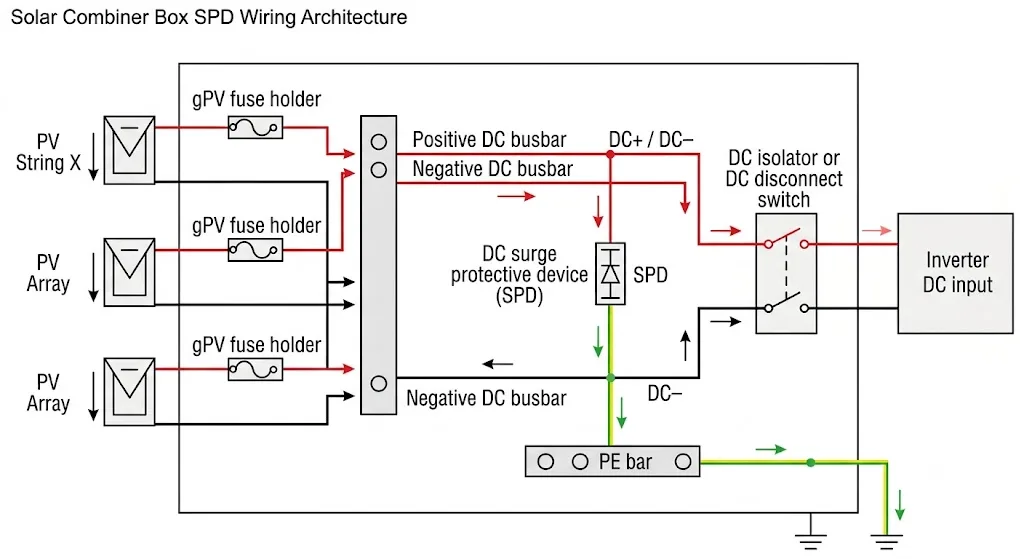
Bagaimana SPD Terhubung dengan Pegangan Sekering, Isolator dan Pemutus
Komponen ini muncul dalam wadah yang sama, tetapi mereka tidak membentuk satu rantai perlindungan yang dapat dipertukarkan. Untuk tinjauan pengkabelan, pertanyaan penting adalah di mana setiap komponen berada terkait dengan jalur arus normal dan cabang SPD.
| Komponen | Posisi dalam pengkabelan | Apa yang perlu diverifikasi pada gambar |
|---|---|---|
| Penghimpun sekering | Terpasang secara seri dengan penghantar string PV yang sesuai | Polaritas yang benar, alokasi string dan koneksi ke titik pengumpulan |
| SPD DC | Terkoneksi sebagai cabang paralel dari node DC yang dilindungi ke PE | Pemetaan terminal, mode perlindungan, titik cabang dan jalur PE |
| Isolator DC | Terpasang secara seri dengan jalur keluaran DC utama | Sisi mana yang tetap terlindungi saat isolator dibuka |
| Pemutus DC | Dipasang pada jalur arus utama atau cabang yang dirancang | Susunan kutub, arah jika berlaku, dan koordinasi dengan desain yang disetujui |
| Batang PE | Tersambung ke pembumian enclosure dan sistem pentanahan proyek | Koneksi SPD langsung, kontinuitas, dan penghindaran loop yang tidak perlu |
Sekring string tidak boleh secara otomatis dianggap sebagai perangkat proteksi cabang SPD. Jika diperlukan proteksi cadangan SPD terpisah, jenis, rating, dan lokasinya harus mengikuti instruksi produsen SPD dan kajian hubung singkat proyek.
Di Mana Seharusnya Cabang SPD Dihubungkan?
SPD harus dihubungkan ke node DC yang dimaksudkan untuk dilindungi oleh desain. SPD tidak boleh dipasang seri di antara string PV dan inverter seolah-olah arus beban normal harus melewatinya.
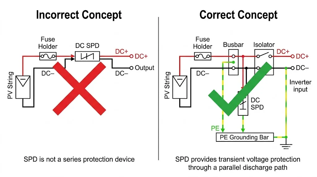
Periksa di mana cabang SPD terhubung secara fisik, konduktor mana yang dilindunginya, apakah isolator yang terbuka mengubah zona terlindungi, dan apakah koneksi PE mencapai titik bonding yang ditentukan secara langsung.
Cara Menghubungkan DC+, DC− dan PE
Label terminal pada SPD aktual lebih diprioritaskan daripada diagram umum. SPD PV yang berbeda dapat menggunakan rangkaian proteksi internal, susunan modul, dan penandaan terminal yang berbeda. Karena itu, langkah berikut adalah metode verifikasi, bukan pengganti lembar instruksi produk.
Koneksi DC+
Telusuri node proteksi positif yang disetujui pada gambar. Hubungkan hanya ke terminal SPD yang ditetapkan untuk DC+ atau jalur proteksi positif yang sesuai. Pastikan sambungan diambil dari sisi sekring, isolator, atau pemutus yang dimaksud.
Koneksi DC−
Telusuri node proteksi negatif secara terpisah. Jangan berasumsi bahwa konduktor negatif dibumikan ke tanah. Banyak susunan PV beroperasi dengan kedua kutub terisolasi dari tanah, sehingga topologi SPD harus sesuai dengan sistem PV yang sebenarnya.
Koneksi PE
Hubungkan terminal pembumian protektif SPD ke batang PE yang ditentukan atau titik bonding equipotensial menggunakan rute yang ditetapkan oleh desain. Pengaturan pembumian dan konduktor protektif harus mengikuti aturan instalasi yang berlaku dan dokumentasi proyek [3][4].
Polaritas yang benar memang perlu, tetapi tidak cukup. Gambar yang benar secara teknis juga harus menunjukkan node proteksi yang dimaksud, mode proteksi internal SPD, dan jalur impedansi rendah ke PE.
Haruskah SPD Sebelum atau Sesudah Isolator DC?
Tidak ada jawaban universal yang dapat diterapkan tanpa gambar sistem. Posisi yang benar bergantung pada konduktor dan peralatan mana yang harus tetap terlindungi saat isolator dibuka.
SPD di sisi array dari isolator
Susunan ini dapat mempertahankan proteksi lonjakan untuk konduktor dan peralatan di sisi array. Namun, cabang SPD dapat tetap bertegangan dari array PV setelah isolator dibuka. Prosedur pemeliharaan harus memperhitungkan kondisi ini.
SPD di sisi inverter dari isolator
Susunan ini dapat memungkinkan isolator memutus SPD dari array, tergantung pada rangkaian lengkapnya. Susunan ini mungkin tidak melindungi semua konduktor hulu saat isolator dibuka.
Proteksi pada kedua sisi
Beberapa arsitektur sistem memerlukan proteksi yang terkoordinasi di lebih dari satu lokasi karena panjang konduktor, zona proteksi petir, paparan peralatan, atau penilaian risiko proyek. Itu adalah keputusan desain sistem dan tidak boleh disimpulkan dari gambar combiner box generik.
Tandai cabang SPD dan batas isolator dengan jelas pada diagram satu garis. Lalu verifikasi kondisi bertegangan, zona terlindungi, dan status isolasi pemeliharaan sebelum menyetujui produksi.
Proses Verifikasi Pengkabelan dan Gambar SPD Langkah demi Langkah
- Konfirmasi data rangkaian PV. Verifikasi tegangan DC maksimum, polaritas konduktor, susunan string, dan peralatan yang terhubung di sisi hilir.
- Buka diagram pengkabelan SPD yang spesifik. Konfirmasi setiap penandaan terminal dan mode proteksi internal. Jangan melakukan pengkabelan hanya berdasarkan tampilan produk.
- Identifikasi node DC yang terlindungi. Tandai titik cabang DC+ dan DC− yang tepat pada skema combiner box.
- Identifikasi batas isolator. Konfirmasi konduktor mana yang tetap bertegangan dan terlindungi saat isolator DC utama dibuka.
- Lakukan penataan konduktor SPD. Jaga jalur konduktor terlindungi dan PE tetap pendek, langsung, dan bebas dari loop yang tidak perlu atau belokan tajam.
- Hubungkan titik PE yang ditentukan. Verifikasi kontinuitas antara terminal PE SPD, bar PE, pembumian enklosur, dan sambungan pembumian proyek.
- Periksa persyaratan proteksi cabang. Jika produsen SPD mensyaratkan proteksi cadangan eksternal, verifikasi perangkat yang ditentukan dan lokasinya.
- Periksa polaritas, torsi, dan terminasi konduktor. Gunakan petunjuk produk dan dokumen manufaktur yang disetujui untuk ukuran konduktor, panjang pengupasan, dan torsi terminal.
- Catat konfigurasi akhir. Pastikan gambar yang dirilis, label, bill of materials, dan model SPD yang dipasang semuanya merujuk pada susunan kabel yang sama.
Cara Membaca Diagram Pengkabelan SPD PV 2P dan 3P
“2P” dan “3P” saja tidak cukup untuk menyetujui pengkabelan. Bergantung pada pemasok, istilah ini dapat menggambarkan jumlah modul, lebar enklosur, atau rangkaian internal tertentu.
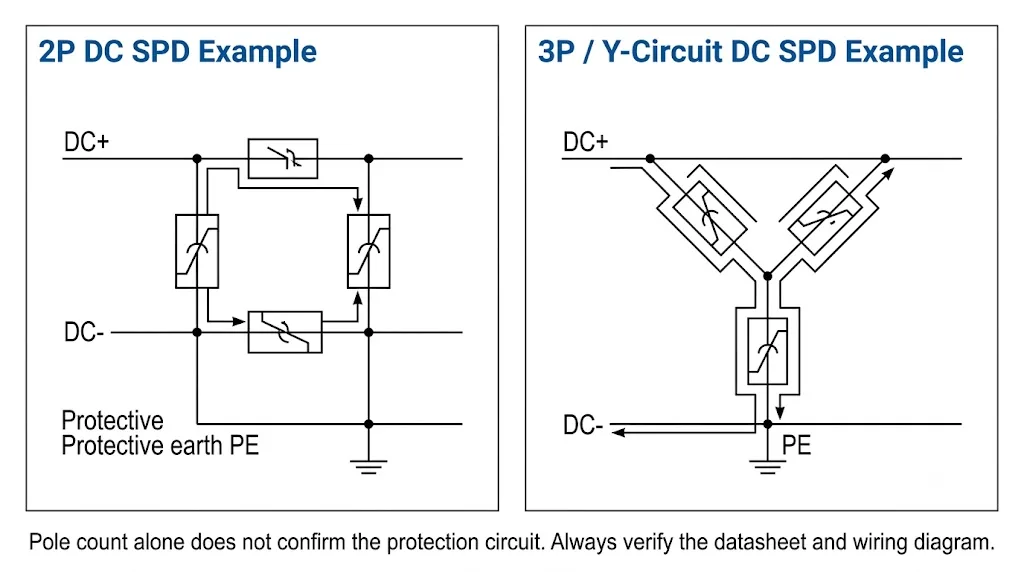
Sebelum persetujuan pengkabelan, pastikan:
- terminal mana yang terhubung ke DC+;
- terminal mana yang terhubung ke DC−;
- terminal mana yang terhubung ke PE;
- apakah rangkaian mencakup proteksi antara DC+ dan DC−;
- apakah elemen proteksi membentuk rangkaian Y atau topologi lain;
- apakah produk yang dipilih telah diuji untuk aplikasi DC PV yang dimaksud berdasarkan IEC 61643-31 [2].
Mengapa Ucpv Harus Dikonfirmasi Sebelum Pengkabelan Dihidupkan?
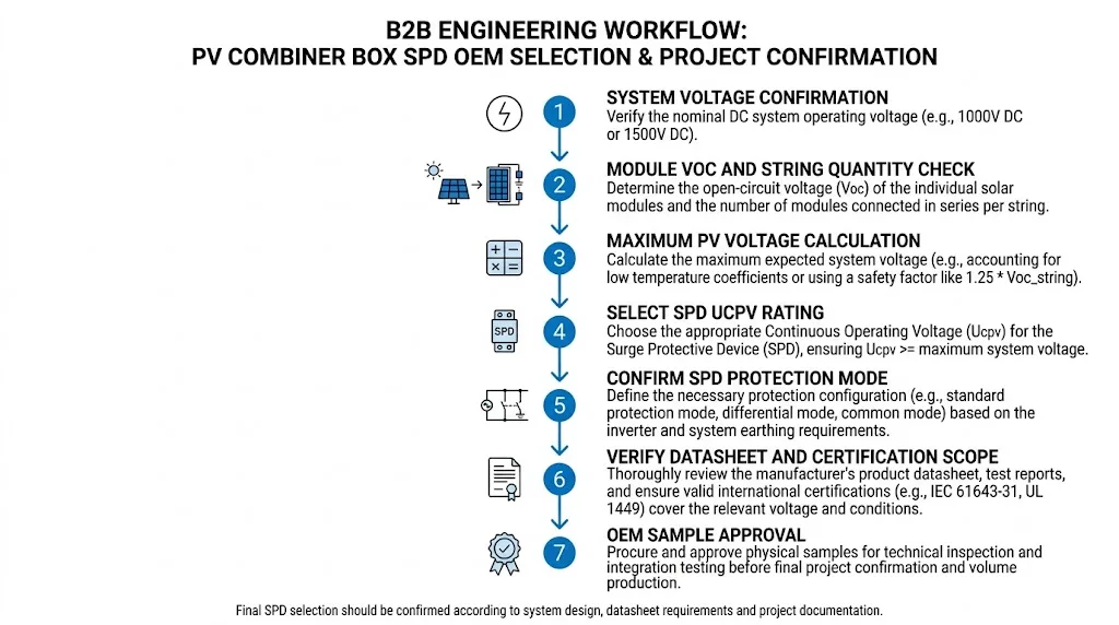
Halaman ini bukan panduan umum pemilihan SPD PV, tetapi verifikasi tegangan tetap merupakan langkah wajib dalam persetujuan pengkabelan. Sambungan yang digambar dengan benar tetap dapat tidak aman atau tidak andal jika SPD yang dipasang tidak sesuai dengan tegangan maksimum PV aktual.
Periksa tegangan rangkaian terbuka modul, jumlah modul yang disusun seri, dan perhitungan tegangan suhu rendah pada proyek. Kemudian verifikasi bahwa Ucpv SPD dan mode proteksi internal sesuai dengan desain akhir. Jangan menyetujui perangkat hanya karena labelnya bertuliskan “1000V” atau “1500V.”
Panjang Koneksi SPD dan Pengaturan PE
Arus surja berubah dengan cepat. Karena itu, induktansi dari konduktor sambungan turut menambah tegangan selama pelepasan. Untuk alasan ini, panduan aplikasi IEC dan instruksi produsen SPD umumnya mensyaratkan sambungan yang pendek dan langsung [1].
Selama peninjauan tata letak panel:
- tempatkan SPD dekat dengan node DC yang dilindungi dan titik sambungan PE;
- hindari merutekan konduktor DC dan PE mengelilingi perangkat yang tidak terkait;
- hindari loop konduktor yang besar;
- hindari berbagi jalur memutar yang tidak perlu sebelum mencapai batang PE;
- susun konduktor masuk dan keluar agar mengurangi kopling yang tidak diinginkan;
- ikuti penampang konduktor dan persyaratan terminal dalam dokumentasi produk.
Susunan yang dapat diterima bergantung pada standar yang berlaku, desain SPD, tata letak boks, dan instruksi produsen. Catat perutean aktual pada gambar produksi ketika geometri sambungan memengaruhi persetujuan.
Kesalahan Umum dalam Pengkabelan SPD Kotak Penggabungan Solar
| Kesalahan pengkabelan | Mengapa ini penting | Koreksi yang diperlukan |
|---|---|---|
| SPD ditampilkan secara seri dengan keluaran PV | Menyesatkan fungsi SPD dan dapat menghasilkan rangkaian yang tidak valid | Gambar ulang SPD sebagai cabang proteksi paralel yang disetujui |
| Terminal DC+ dan DC− diasumsikan dari posisi modul | Urutan modul eksternal mungkin tidak memperlihatkan topologi proteksi internal | Gunakan diagram terminal dan rangkaian yang spesifik untuk model tersebut |
| Konduktor PE yang panjang atau membentuk loop | Menambah impedansi dan dapat meningkatkan tegangan yang muncul pada peralatan yang dilindungi | Gunakan jalur pengikatan langsung terpendek yang dapat diterapkan |
| Posisi isolator tidak dipertimbangkan | Zona yang salah mungkin tetap tidak terlindungi atau tanpa sengaja tetap bertegangan | Verifikasi status proteksi dan isolasi pada diagram satu garis |
| Sekering string diperlakukan sebagai proteksi cadangan SPD | Perangkat mungkin tidak menyediakan koordinasi yang diperlukan | Periksa petunjuk proteksi cadangan dari produsen SPD |
| Label 1000V atau 1500V diterima tanpa perhitungan | SPD yang dipasang mungkin tidak sesuai dengan tegangan maksimum PV yang sebenarnya | Verifikasi tegangan array dan Ucpv sebelum diberi energi |
Daftar Periksa Inspeksi Pengkabelan SPD Kotak Penggabungan PV Akhir
Lakukan pemeriksaan ini sebelum merilis gambar, menyetujui sampel, atau memberi energi pada kotak combiner.
Butuh Tinjauan Pengkabelan SPD Kotak Penggabungan PV?
Bagikan diagram satu garis kotak penggabung, tegangan PV maksimum, lembar data SPD, posisi isolator, dan pengaturan PE. LEEYEE dapat membantu meninjau koneksi SPD yang diusulkan dan mengidentifikasi detail yang masih memerlukan konfirmasi proyek.
FAQ Pengkabelan SPD Kotak Penggabungan Solar
Apakah DC SPD dihubungkan secara seri atau paralel?
PV DC SPD biasanya dihubungkan sebagai cabang perlindungan lonjakan arus paralel. Arus beban susunan normal tidak boleh melewati SPD seolah-olah itu adalah sekring, isolator, atau pemutus arus.
Di mana kabel PE dari SPD dihubungkan?
Ini terhubung ke batang PE atau titik ikatan ekuipotensial yang ditentukan sebagaimana ditunjukkan dalam desain yang disetujui. Jalurnya harus pendek dan langsung, sementara ukuran konduktor dan terminasi harus mengikuti dokumen produk dan proyek.
Haruskah SPD dipasang sebelum atau sesudah isolator?
Sisi yang benar bergantung pada zona perlindungan yang dituju dan kondisi isolasi. Gambar harus menunjukkan peralatan mana yang tetap terlindungi dan konduktor SPD mana yang tetap dialiri listrik saat isolator terbuka.
Bisakah sekring string PV digunakan sebagai sekring cadangan SPD?
Jangan berasumsi demikian. Sekring string dan proteksi cabang SPD menjalankan fungsi yang berbeda. Setiap proteksi cadangan SPD eksternal yang diperlukan harus mengikuti instruksi spesifik SPD dan penilaian koordinasi proyek.
Bisakah saya memasang kabel SPD PV 2P dan 3P dengan cara yang sama?
Tidak aman tanpa memeriksa diagram sirkuit. Jumlah modul atau kutub tidak selalu menunjukkan mode proteksi internal. Gunakan diagram terminal yang tepat untuk model yang dipilih.
Mengapa Ucpv harus diperiksa pada halaman pengabelan?
Karena sambungan terminal yang benar tidak membuat SPD dengan peringkat yang salah menjadi sesuai. Peringkat tegangan perangkat dan mode perlindungan harus diverifikasi sebelum sirkuit yang telah selesai dialiri listrik.
Referensi
- IEC 61643-32, Perangkat pelindung lonjakan arus tegangan rendah — Bagian 32: Perangkat pelindung lonjakan arus yang dihubungkan ke sisi DC instalasi fotovoltaik — Prinsip pemilihan dan penerapan.
- IEC 61643-31, Perangkat pelindung lonjakan arus tegangan rendah — Bagian 31: Persyaratan dan metode pengujian untuk SPD pada instalasi fotovoltaik.
- IEC 60364-7-712, Instalasi listrik tegangan rendah — Persyaratan untuk instalasi atau lokasi khusus — Sistem pasokan daya fotovoltaik surya.
- IEC 60364-5-54, Instalasi listrik tegangan rendah — Pemilihan dan pemasangan perlengkapan listrik — Pengaturan pembumian dan konduktor pelindung.
- Petunjuk pemasangan, lembar data, diagram sirkuit, dan persyaratan perlindungan cadangan yang diterbitkan untuk model SPD spesifik yang digunakan dalam proyek.
