
Designing an ATS cabinet around a compact integrated automatic transfer switch is mainly an integration task: the panel builder must provide correct source and load connections, external protection, cable space, control interfaces, manual-operating access and maintenance clearance around the ATS.
This guide focuses on the type of compact integrated ATS supplied by LEEYEE rather than large draw-out, bypass-isolation or custom switchgear architectures. The aim is to help panel builders integrate the ATS into a distribution or control cabinet without creating wiring, operation or maintenance problems.
Daftar Isi
Product Scope: Which ATS Does This Guide Apply To?
LEEYEE's standard ATS product format is a compact integrated unit with the transfer mechanism, front operating controls and status indication combined in one device. The standard application focus is open-transition source transfer.
Closed-transition systems, bypass-isolation systems and CB-class transfer architectures are different engineered solutions. They are discussed only where a panel builder needs to understand the boundary of the standard compact ATS configuration; they should not be assumed to be standard LEEYEE product functions.
Quick Answer: Design the Cabinet Around the Real ATS
For a compact ATS cabinet, use this sequence:
- Confirm sources
- Select ATS
- Confirm 2P / 3P / 4P
- Plan protection
- Check terminals
- Plan cables
- Leave operating space
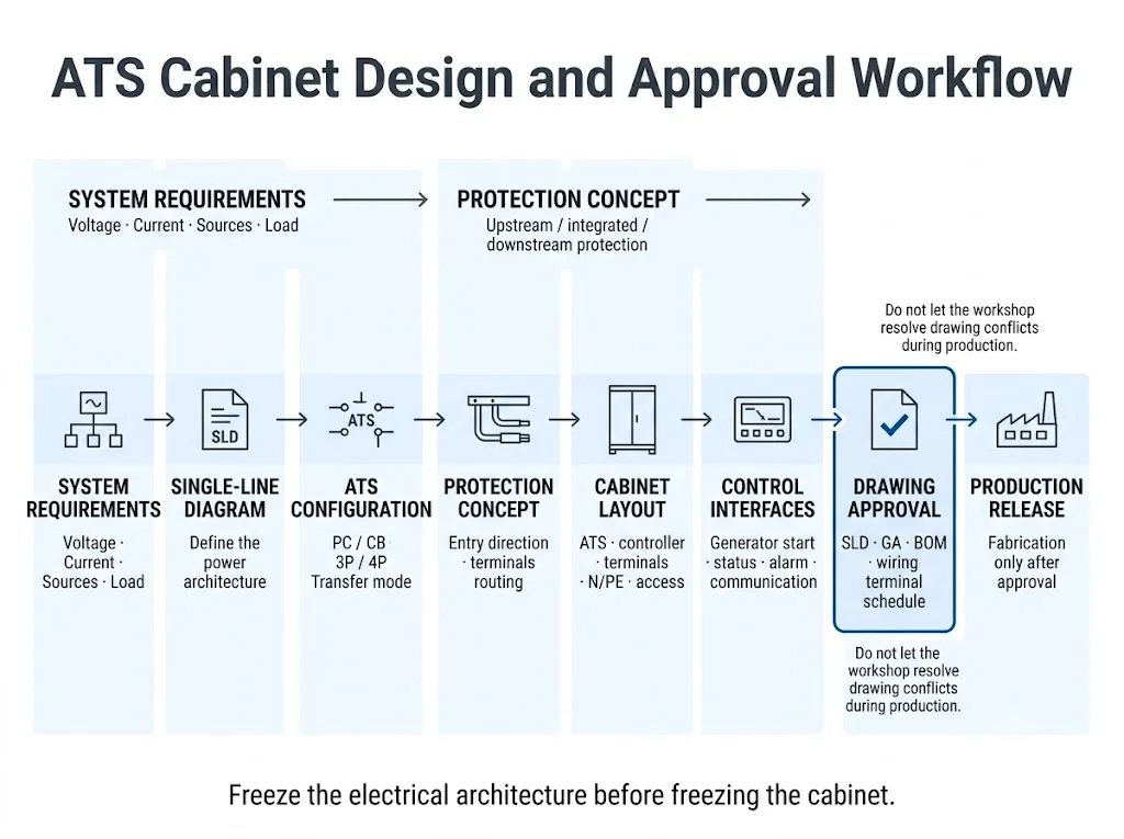
- Approve drawings
Do not start by choosing an enclosure and then try to make the ATS fit. Confirm the actual ATS model, pole configuration, terminal orientation, external protection concept and cable-entry direction first.
IEC 60947-6-1:2026 is the current IEC standard covering transfer switching equipment within its scope. For the completed low-voltage cabinet, IEC 61439-1 and the applicable assembly-specific part may also be relevant. The exact standard and verification requirements must be confirmed for the actual project and destination market.[1][2][3]
1. Start With the Power Path: Source A, Source B and Load
A compact ATS is easier to integrate when the power path is settled before the mechanical layout.
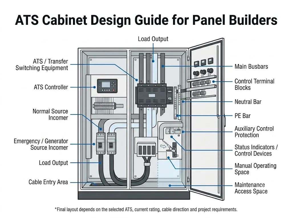
The panel builder should first identify the normal source, alternate source and load output.
| Koneksi | Fungsi | Confirm Before Layout |
|---|---|---|
| Normal source | Utility or preferred supply | Voltage, current, protection and incoming cable direction |
| Emergency source | Generator or alternate supply | Source type, sensing, protection and generator interface |
| Load output | Supplies the downstream load | Outgoing cable direction, load current and termination method |
Panel-builder meaning: if the source and load directions are not fixed, the ATS cabinet layout is not ready to be frozen.
2. Understand What the Compact ATS Already Integrates
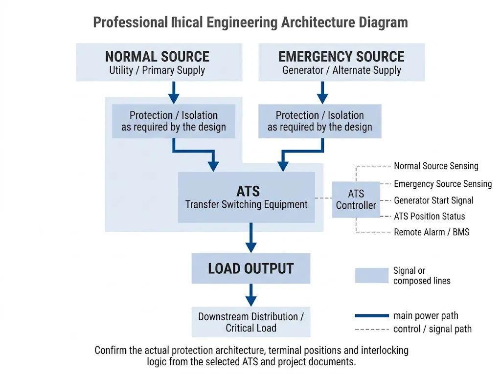
With this product architecture, the ATS itself already combines the transfer mechanism with local operating and indication functions. The cabinet does not need to recreate the ATS as a separate collection of two switching devices and an external transfer mechanism.
This changes the panel builder's job. The main task is to integrate the ATS correctly into the cabinet rather than redesign its internal transfer mechanism.
Functions on the ATS
- Source transfer mechanism
- Auto / Manual operation
- Local operating handle
- Source and load status indication according to the selected model
Functions Around the ATS
- Proteksi eksternal yang diperlukan
- Incoming and outgoing conductors
- Neutral and PE arrangement
- Generator or remote-control wiring where supported
- Cabinet labelling and documentation
Use the real compact ATS dimensions, pole count, power terminals, control terminals and manual-operating requirements from the selected model before the GA drawing is approved.
3. Position the ATS Where It Can Still Be Operated After Wiring
Compact does not mean that the ATS can be placed anywhere inside the enclosure.
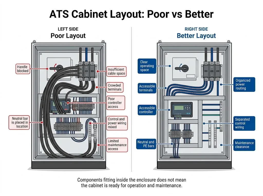
The front of the device must remain usable after the cabinet is fully wired. The panel builder should check whether technicians can see the status indication, change between permitted Auto and Manual operating modes, reach the manual mechanism and inspect the power terminals without removing unrelated conductors.
Check four kinds of space
- Mounting space: enough room to install and secure the ATS.
- Termination space: enough room for incoming and outgoing conductors and lugs.
- Operating space: the front handle, selector and indicators remain accessible.
- Maintenance space: terminals and the ATS can be inspected or replaced according to the project maintenance plan.
Check the layout again after adding the real cable sizes, terminal hardware, neutral conductor and door-mounted equipment.
4. Plan the Protection Around the ATS, Not Inside It
A compact transfer switch should not automatically be treated as the complete short-circuit protection system for the cabinet.
The project designer must determine the required upstream or downstream protective devices according to the ATS characteristics, available fault level, conductor design, distribution system and applicable project requirements.
IEC 60947-6-1 defines requirements for transfer switching equipment, while the completed cabinet can also require assembly-level design and verification under the applicable IEC 61439 requirements.[1][2][3]
The correct protection arrangement depends on the selected ATS, system fault conditions and project design. Confirm the complete protection concept before the cabinet BOM is approved.
5. 2P, 3P and 4P Change the Cabinet Connection Layout
Pole configuration affects more than the ATS part number.
A 4-pole ATS switches the neutral conductor in addition to the three phase conductors. This changes the number of main conductors through the device and can affect termination space, neutral routing and cabinet organisation.
Whether a project should use 3P or 4P in a three-phase system depends on the earthing arrangement, generator neutral configuration and project requirements. Do not select a switched neutral only because 4P appears to be a higher specification.
Changing from a non-switched neutral arrangement to a switched-neutral arrangement after production has started can affect the ATS, conductors, neutral bar and cabinet layout.
6. Keep the Cabinet Design Aligned With the Standard LEEYEE ATS Architecture
The standard LEEYEE compact ATS is intended primarily for open-transition transfer. In an open-transition sequence, the load is disconnected from one source before it is connected to the other source.
This is different from closed-transition transfer, where specially designed equipment can provide controlled source overlap under defined conditions. IEC 60947-6-1:2026 includes separate requirements for ATSE with closed-transition capability.[1]
If a project specifies closed transition, treat it as a different engineered transfer architecture and confirm the required equipment, source conditions and project approvals before proceeding.
What about bypass isolation?
A maintenance bypass or bypass-isolation arrangement is also not part of the standard compact ATS architecture described in this guide.
IEC 60947-6-1:2026 includes specific requirements for bypass/isolation transfer switch equipment.[1] If a project requires the load to remain supplied while the ATS itself is isolated for maintenance, that requirement should be treated as an engineered cabinet extension rather than assumed to be built into the standard ATS.
Such a change can affect switching equipment, interlocking, enclosure dimensions and wiring architecture, so it should be identified at the specification stage.
7. Plan Control Signals Without Rebuilding the ATS Controller
The compact ATS already performs its transfer-control function. The panel builder should concentrate on the external signals actually required by the project and supported by the selected model.
Depending on the ATS version and project, relevant functions may include:
| Fungsi | Arti Desain Panel |
|---|---|
| Normal / Emergency Available | Source-availability status used for local indication or control logic where supported |
| Load to Normal / Emergency | Indicates which source is supplying the load where status outputs are available |
| Auto / Manual | Local operating mode must remain physically accessible |
| Generator start | Confirm the required dry-contact or control interface from the selected model |
| Fault alarm / remote status | Reserve terminals only when the selected ATS supports the required signal |
| BMS / communication | Project-specific; do not assume every compact ATS includes a communication interface |
Procurement meaning: confirm the exact required I/O before ordering. Similar-looking ATS models can have different auxiliary and remote-control functions.
8. Cable Routing Is Often More Important Than Empty Cabinet Space
A compact ATS reduces the device footprint, but the power cables still need enough space to approach the terminals correctly.
Periksa:
- normal-source cable entry;
- emergency-source cable entry;
- load cable exit;
- conductor bending space;
- terminal and lug access;
- cable support;
- neutral conductor routing;
- PE connection;
- separation and identification of control wiring.
Do not publish or apply one universal cable-bending distance without confirming conductor construction, size, lug type, ATS terminals and applicable installation requirements.
Top entry or bottom entry?
Either arrangement can be suitable if it matches the project and the real terminal layout. The important point is to confirm cable direction before finalising the cabinet, not after the ATS mounting plate has already been fabricated.
9. Busbars and Conductors Must Follow the Complete Assembly Design
The ATS current rating alone is not enough to define the busbar size or complete conductor arrangement.
IEC 61439-1 establishes general construction, technical-characteristic and verification requirements for low-voltage switchgear and controlgear assemblies. IEC 61439-2 provides specific requirements for power switchgear and controlgear assemblies within its scope.[2][3]
The panel design can also depend on fault conditions, conductor material, connection method, temperature-rise performance, support arrangement and enclosure conditions.
Select and verify the complete conductor system according to the actual installation, applicable rules and panel design.
10. Ventilation Should Be Based on the Finished Cabinet
A compact ATS cabinet does not automatically need a fan.
Thermal performance depends on the ATS, protective devices, conductors, connections, auxiliary devices, enclosure dimensions, ambient temperature and ventilation conditions.
IEC 61439 includes temperature-rise verification requirements for low-voltage assemblies within its scope.[2][3]
The panel builder should therefore evaluate the completed assembly rather than assume that a small ATS means heat can be ignored.
At the same time, adding ventilation openings can affect the enclosure's ingress-protection performance. Thermal management and enclosure protection should be reviewed together.
11. Review the Cabinet From the Operator's Position
Before approving the GA drawing, imagine the cabinet fully wired and installed.
- Can the ATS front indication still be seen?
- Can Auto / Manual operation be accessed without removing cables?
- Can the manual handle move through its required travel?
- Can normal and emergency source terminals be inspected?
- Can the load terminals be reached for tightening and inspection?
- Can auxiliary terminals be identified during commissioning?
- Can the ATS be removed if replacement is required?
Add the actual cables to the drawing mentally—or in CAD—and check the ATS again. Many poor cabinet layouts become obvious only after the conductors are included.
12. Approve the Drawings Before Production
The compact ATS simplifies the switching device, but it does not remove the need for disciplined panel documentation.
Electrical Documents
- Diagram satu garis
- Power wiring diagram
- Control schematic
- Terminal schedule
- Pengaturan perlindungan
Production Documents
- General arrangement
- Approved BOM
- Mounting dimensions
- Label and nameplate drawing
- Project-required verification records
If the SLD, GA, BOM and wiring drawings disagree, resolve the discrepancy before fabrication. Do not leave the workshop to decide which version is correct.
13. Common Mistakes When Integrating a Compact ATS
- Choosing the cabinet before confirming the ATS dimensions and terminals.
- Blocking the front manual-operating mechanism with cables or door hardware.
- Leaving too little room for two incoming sources plus the load conductors.
- Assuming the ATS itself replaces all external short-circuit protection.
- Changing from 3P to 4P after the neutral layout has already been completed.
- Assuming every ATS model provides the same generator-start or remote-status contacts.
- Mixing high-current power wiring and control wiring without a clear routing plan.
- Applying closed-transition logic to a standard open-transition ATS.
- Treating maintenance bypass as a simple accessory that can always be added later.
- Releasing production before the SLD, GA, BOM and wiring documents agree.
14. Compact ATS Cabinet Checklist Before Production Release
| Barang | Confirm Before Production |
|---|---|
| System voltage / frequency | Matches the selected ATS and project |
| Arus yang dinilai | Confirmed from the load and project design |
| Normal / emergency sources | Source type and connection arrangement confirmed |
| ATS model | Actual compact ATS dimensions and terminals available |
| 2P / 3P / 4P | Pole configuration and neutral strategy approved |
| Perlindungan | External protection concept approved |
| Cable direction | Normal, emergency and load routes confirmed |
| Manual operation | Front operating space remains clear after wiring |
| Control signals | Generator start, status and remote functions checked against model |
| Neutral / PE | Termination and access planned |
| Thermal design | Finished assembly evaluated |
| Dokumen | SLD, GA, BOM and wiring drawings agree |
What Should You Send Before Ordering the ATS?
For an OEM panel or distribution-board project, sending only “I need a 63 A ATS” is usually not enough.
Prepare:
- system voltage and frequency;
- single-phase or three-phase system;
- rated current;
- normal and emergency source type;
- 2P, 3P or 4P requirement;
- earthing and neutral arrangement;
- generator-start requirement;
- required status or remote signals;
- cabinet installation space;
- top or bottom cable-entry requirement;
- applicable project standard or specification;
- OEM label, nameplate or packaging requirement.
Where available, include the SLD or preliminary cabinet drawing. This allows the ATS configuration to be checked against the actual panel rather than selected from current rating alone.
Need Help Confirming a Compact ATS for Your Cabinet?
Send your system voltage, rated current, source arrangement, pole configuration, cabinet drawing and required control functions. LEEYEE can review the information and help confirm a suitable standard compact ATS configuration for panel integration.
If the project requires closed transition, bypass isolation, CB-class transfer architecture or another non-standard function, identify it before model selection so the requirement can be evaluated separately.
ATS Cabinet Design FAQ
Can a compact ATS be installed inside a distribution cabinet?
Yes, when the cabinet provides suitable mounting, connections, external protection, cable space, operating access and environmental conditions for the selected ATS. Final installation requirements should be checked against the actual model documentation and project design.
Does the cabinet still need breakers if it already has an ATS?
The ATS should not automatically be assumed to provide all required short-circuit and overcurrent protection. The upstream and downstream protection arrangement must be confirmed from the ATS characteristics, system fault conditions and project design.
Should I choose a 3P or 4P ATS for a three-phase cabinet?
The choice depends on whether the neutral should be switched. Confirm the system earthing arrangement, generator neutral configuration and project requirements before selecting 3P or 4P.
Does a compact ATS require a separate controller in the cabinet?
Not necessarily. The standard compact integrated ATS architecture already contains the transfer-control function. External devices should only be added when the project requires supported remote control, indication, communication or another auxiliary function.
Can the standard compact ATS be used for closed transition?
The standard LEEYEE compact ATS configuration described in this guide is intended primarily for open-transition applications. Closed transition is a different engineered architecture and should not be assumed to be available by changing controller settings alone. IEC 60947-6-1:2026 contains separate provisions for closed-transition ATSE.[1]
Does every ATS cabinet need a maintenance bypass?
No. Bypass/isolation is project-specific. If the project requires the ATS to be isolated while the load remains supplied, the bypass arrangement should be designed as part of the overall cabinet architecture rather than treated as a standard function of the compact ATS.[1]
What should be confirmed before the ATS cabinet drawing is approved?
Confirm the selected ATS model, rated current, source arrangement, pole configuration, protection concept, cable-entry direction, control signals, neutral and PE arrangement, manual-operating access, environmental conditions and the consistency of the SLD, GA, BOM and wiring drawings.
Referensi
- IEC. IEC 60947-6-1:2026, Peralatan sakelar dan pengatur tegangan rendah – Bagian 6-1: Peralatan multifungsi – Peralatan pengalih transfer, 4th edition, 2026. Halaman publikasi IEC.
- IEC. IEC 61439-1:2020, Low-voltage switchgear and controlgear assemblies – Part 1: General rules, 3rd edition. Halaman publikasi IEC.
- IEC. IEC 61439-2:2020, Low-voltage switchgear and controlgear assemblies – Part 2: Power switchgear and controlgear assemblies, 3rd edition. Halaman publikasi IEC.
