
When a compact automatic transfer switch is installed in a distribution panel, one of the most important questions is not simply which ATS current rating to choose. The panel designer also needs to decide how the ATS is protected, whether MCCBs belong on the source side, load side or both, and how the complete protection architecture should be coordinated.
Daftar Isi
Does a Compact ATS Need an MCCB?
Do not treat a compact ATS as a substitute for the required short-circuit and overload protection of the distribution circuit. The ATS transfers the load between the normal and emergency sources. Circuit breakers or other suitable protective devices perform the required fault-protection functions according to the system design.
An MCCB can therefore be installed before the ATS, after the ATS, or on both sides. Each position has a different protection responsibility. The correct arrangement depends on the selected ATS model, its declared short-circuit data, the available fault current, the source protection, downstream feeder protection and the approved single-line diagram.
Makna pembeli: for a compact LEEYEE ATS application, first confirm what must be protected and what fault current is available. Do not select an MCCB only because its ampere rating matches the ATS.
This article is written around the compact integrated ATS architecture supplied by LEEYEE, where the transfer mechanism, operating controls and source-status functions are integrated into one compact device for installation in a distribution panel.
Breaker-based Class CB transfer systems are mentioned only to explain why some ATS diagrams use circuit breakers as the switching devices. They should not be interpreted as the standard physical appearance or supply architecture of the compact LEEYEE ATS shown in this application.
The exact IEC class, Iq, Icw and permitted protective-device combinations must be confirmed from the technical documents for the selected ATS model. They should not be inferred from product appearance alone.
ATS and MCCB Have Different Responsibilities
The formal IEC term is transfer switching equipment (TSE); an automatically operated version is ATSE. IEC 60947-6-1:2026 applies to transfer switching equipment, while IEC 60947-2:2024 applies to circuit-breakers within its scope. [1][2]
| Device / Function | Main Job | What the Panel Designer Must Confirm |
|---|---|---|
| Compact ATS | Transfers the load between two power sources. | Rated current, voltage, poles, operating mode, control functions and declared short-circuit performance. |
| MCCB / SCPD | Provides fault interruption and circuit protection within its declared ratings. | Rated current, Icu/Ics, trip characteristics, system voltage and coordination with the ATS. |
| Protection coordination | Determines how the protection system behaves during a fault. | Fault level, clearing behaviour, selectivity requirements and manufacturer coordination data. |
Kesimpulan pengadaan: the ATS selects the power source; the protection system determines how a fault is safely interrupted.
Should the MCCB Be Before or After the ATS?
There is no universal rule that an MCCB must always be installed before or always after a compact ATS. The breaker position depends on the protection zone it is intended to serve.
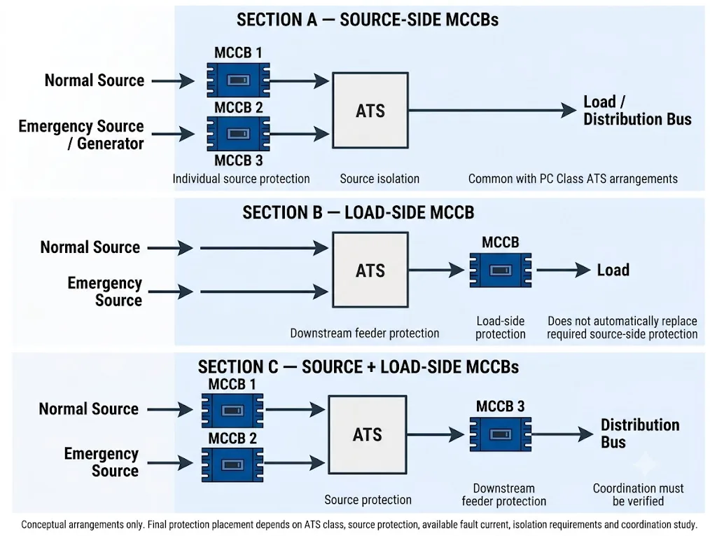
1. MCCB on Each Source Before the ATS
A common distribution-panel architecture places one protective device on the normal source and another on the emergency source before the ATS.
This allows each source circuit to be protected and isolated according to its own electrical conditions. It is especially important when the ATS short-circuit performance is declared in combination with a specified short-circuit protective device.
ABB technical guidance explains that rated conditional short-circuit current, IQ, applies to transfer switching equipment protected by a specified SCPD under the declared conditions. [3]
Makna pembeli: the source-side protective device should be selected from system data and ATS coordination information, not only from ATS rated current.
2. MCCB After the ATS
An MCCB installed after the ATS usually protects the outgoing feeder, cable or downstream load circuit.
A load-side MCCB does not automatically replace the protection required on the incoming source side. The two locations protect different parts of the system.
3. Source-Side MCCBs Plus a Load-Side MCCB
A distribution panel may use protection on both incoming sources and another breaker after the ATS. This creates separate protection zones for the source feeders and outgoing feeder.
However, more breakers do not automatically mean better protection. Their breaking capacity and trip behaviour still have to be coordinated. Where selectivity is required, the protective device closest to the fault should operate without unnecessarily disconnecting healthy upstream sections of the system. [5]
Why This Guide Mentions PC Class and CB Class
PC Class and CB Class are useful because they explain why different ATS systems show different circuit-breaker arrangements. They should not be confused with the physical appearance of the compact LEEYEE ATS used as the main product context for this page.
ABB guidance describes Kelas PC transfer switching equipment as capable of making and withstanding its declared short-circuit duty but not intended to interrupt the short-circuit current. Kelas CB equipment uses circuit breakers as part of the transfer switching architecture and can provide short-circuit interruption within the declared breaker performance. [3]
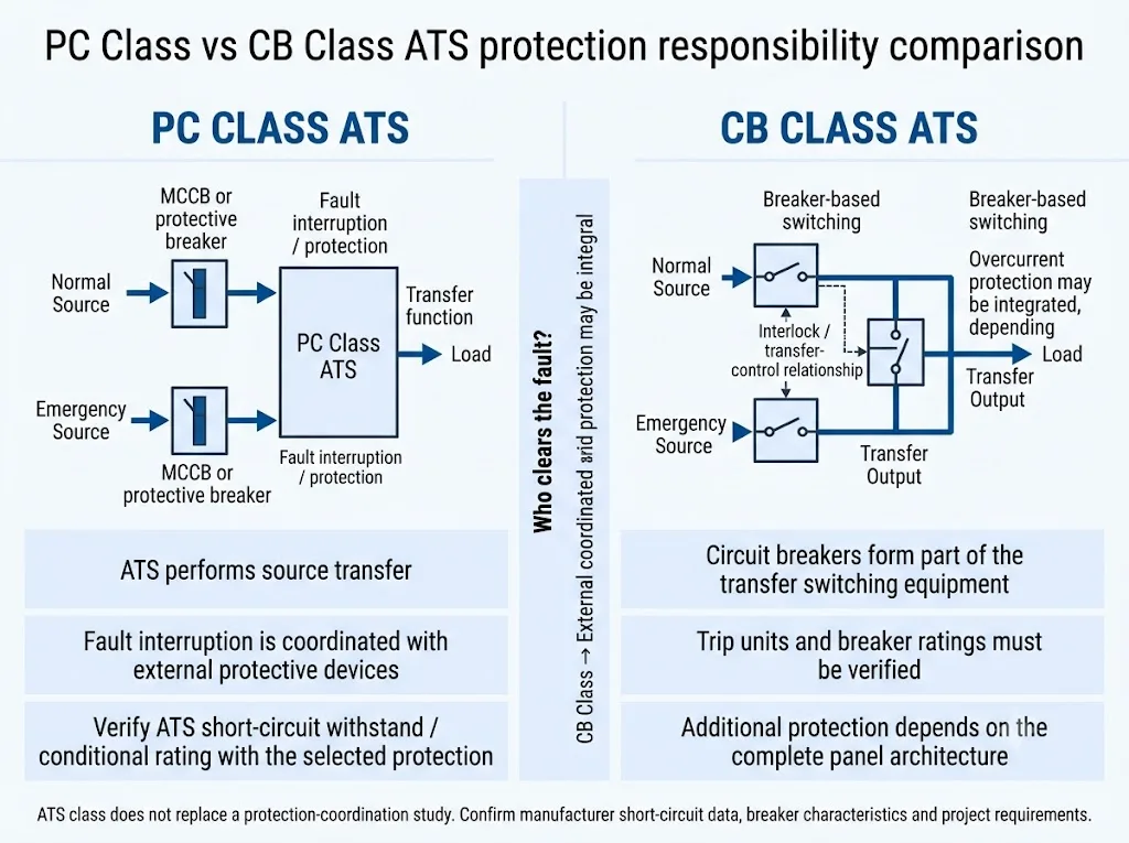
The exact IEC class and short-circuit ratings of a LEEYEE ATS model must come from its datasheet, test documentation or certificate scope. Product appearance by itself is not sufficient evidence for assigning Iq, Icw or an IEC classification.
Do Not Select the MCCB by ATS Ampere Rating Alone
If a compact ATS is rated at a certain current, it may seem logical to choose an MCCB with the same current rating. That is only the beginning of the selection process.
The designer must also verify the prospective short-circuit current, circuit-breaker breaking capacity, trip characteristics and the ATS short-circuit performance. [2][3]
ATS rated current = MCCB rated current does not prove that the two devices form a safe short-circuit coordination.
Four Parameters Worth Checking
- ATS rated current: confirms the continuous current range under the stated operating conditions.
- Iq: where assigned, indicates conditional short-circuit performance with a specified protective device. [3]
- Icw: where assigned, indicates the declared short-time withstand capability of the transfer equipment. [3]
- MCCB Icu / Ics: indicate circuit-breaker short-circuit breaking performance under IEC 60947-2. [2]
Makna pembeli: if a quotation lists only ATS current and MCCB current, ask what short-circuit and coordination information supports the proposed combination.
ATS + MCCB Selection and Coordination Flow
- Confirm the load current. Determine the continuous load and operating conditions.
- Select the compact ATS configuration. Confirm voltage, rated current, poles, operating mode and model-specific technical data.
- Confirm the available fault current. Use the project short-circuit calculation or approved engineering data at the installation point.
- Select the protective device. Check rated current, operating voltage, Icu/Ics and trip characteristics.
- Check the ATS short-circuit data. Where the ATS rating depends on a specified SCPD, verify the exact protective-device combination.
- Check upstream and downstream coordination. Verify selectivity where required by the project.
- Approve the final SLD and BOM. Confirm source protection, downstream protection, isolation, controls and panel requirements.
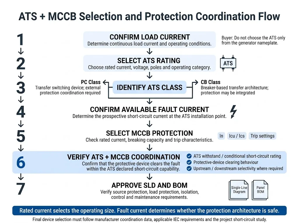
Rated current determines operating size. Fault current determines whether the protection architecture can safely withstand and clear a short circuit.
Example: Compact ATS Between Utility and Generator Sources
How a Panel Builder Should Approach the Protection Scheme
Consider a compact ATS installed between a utility source and an emergency generator. The ATS handles source transfer, while the panel designer still needs to define how each source feeder and the downstream load are protected.
If the outgoing feeder needs separate protection, a load-side MCCB may also be included. That downstream breaker does not automatically replace the protection required for either incoming source.
Do not: duplicate the utility MCCB specification on the generator side simply because the ATS current is the same.
Do: verify each source independently, then check the ATS and protective-device coordination before approving the BOM.
Normal Source and Generator Protection May Be Different
The two ATS sources can have very different fault characteristics. A utility supply backed by a transformer and an emergency generator should not automatically be treated as equivalent short-circuit sources.
The generator-side protective device should therefore be checked using the actual generator and project data instead of mechanically copying the normal-source breaker.
What Changes When the ATS Is Installed Inside a Distribution Panel?
Component compliance and complete-assembly verification are different levels of engineering work. IEC 60947-6-1 applies to transfer switching equipment and IEC 60947-2 applies to circuit-breakers. When those devices are integrated into a low-voltage power switchgear and controlgear assembly, the applicable IEC 61439 requirements may also need to be addressed for the complete panel. [6][7]
Using compliant individual ATS and MCCB components does not by itself complete the verification of the whole switchboard. The assembly design may also need to address short-circuit withstand, temperature rise, conductors, busbars, protective-device integration and other requirements under the applicable assembly standard.
Protection Is Not the Same as Maintenance Isolation
An MCCB can be part of a maintenance-isolation strategy, but fault protection and safe isolation are not automatically the same function.
The project should separately confirm how the compact ATS can be isolated for inspection or replacement and whether additional disconnecting or bypass arrangements are required.
IEC 60947-6-1:2026 also includes requirements for bypass/isolation transfer switching equipment in Annex C. [1]
ATS + MCCB BOM: What Should Be Confirmed?
| BOM Item | Fungsi | Apa yang Perlu Dikonfirmasi |
|---|---|---|
| Compact ATS | Source transfer | Model, poles, current, voltage, control mode and declared short-circuit data. |
| Normal-source MCCB / SCPD | Normal-source feeder protection | Current, Icu/Ics, trip characteristics and ATS coordination. |
| Emergency-source MCCB / SCPD | Generator or emergency feeder protection | Generator/source data, fault current and trip characteristics. |
| Load-side MCCB | Outgoing feeder protection where required | Cable/load current, fault level and downstream coordination. |
| Control / auxiliary signals | ATS control, status and interface functions | Auto/manual functions, source status, alarm contacts and BMS/PLC needs. |
| Panel assembly | Integrates protection, switching and conductors | Busbar, wiring, thermal design, short-circuit verification and applicable IEC 61439 requirements. |
Before Ordering: Send These ATS + MCCB Details
- Diagram satu garis
- Normal-source voltage and frequency
- Emergency-source voltage and frequency
- Arus beban terukur
- Required ATS poles
- Neutral switching requirement
- Prospective short-circuit current, if known
- Normal-source breaker information
- Generator rating and protection information
- MCCB breaking-capacity requirement, if specified
- Trip settings, if already engineered
- Tegangan kontrol
- Auto/manual control requirement
- Auxiliary contacts / BMS / PLC signals
- Applicable project standard
- Kebutuhan panel atau OEM
- Required quantity
- Maintenance/isolation requirement
Need to Confirm the MCCB Arrangement for a Compact ATS?
Send LEEYEE your single-line diagram, source information, load current and existing protection requirements. We can review the compact ATS configuration and identify which protection details still need project confirmation.
Final protection approval should follow the project fault-current study, applicable standards and the model-specific ATS and protective-device data.
Pertanyaan yang Sering Diajukan
Does a compact ATS replace an MCCB?
No. A compact ATS performs the transfer function. The required overcurrent and short-circuit protection must still be provided by the protection architecture of the distribution system. The exact protective device depends on the selected ATS model and project design.
Should the MCCB be before or after the ATS?
Either position can be used for a valid engineering reason. Source-side MCCBs protect incoming circuits and may be required for ATS short-circuit coordination. A load-side MCCB protects the outgoing feeder. Some panels use both.
Can I choose the MCCB just by matching the ATS current?
No. Rated current alone does not confirm short-circuit coordination. Check available fault current, breaker Icu/Ics, trip behaviour and the ATS short-circuit declaration.
Is the LEEYEE compact ATS a breaker-based CB Class ATS?
Do not determine IEC class from product appearance. The exact classification and short-circuit ratings of a selected LEEYEE model should be confirmed from its model-specific technical documentation. The CB Class discussion in this article is included to explain the difference between transfer architectures.
Should the utility and generator sides use the same MCCB?
Not automatically. The two sources can have different operating current, fault contribution and protection requirements. Check each source independently before fixing the breaker model or trip settings.
Referensi
- IEC. IEC 60947-6-1:2026, Low-voltage switchgear and controlgear — Part 6-1: Multiple function equipment — Transfer switching equipment. Halaman publikasi resmi IEC.
- IEC. IEC 60947-2:2024, Low-voltage switchgear and controlgear — Part 2: Circuit-breakers. Halaman publikasi resmi IEC.
- ABB. How to Select an Automatic Transfer Switch Class. Technical guidance covering Class PC, Class CB, Iq, Icw and short-circuit protective-device coordination. ABB Library.
- Schneider Electric. Source Changeover Switches / TransferPacT. Reference information illustrating breaker-based Class CB and switch-disconnector-based Class PC transfer architectures. Schneider Electric.
- ABB. Selectivity Techniques. Technical guidance on protection selectivity and coordination. ABB Low Voltage.
- IEC. IEC 61439-1:2020, Low-voltage switchgear and controlgear assemblies — Part 1: General rules. Halaman publikasi resmi IEC.
- IEC. IEC 61439-2:2020, Low-voltage switchgear and controlgear assemblies — Part 2: Power switchgear and controlgear assemblies. Halaman publikasi resmi IEC.
