
Sebuah automatic transfer switch wiring diagram for a generator panel should make three power connections immediately clear: the utility or normal source, the generator or emergency source, and the common output to the load. A complete engineering review must also confirm neutral treatment, protective earth, source sensing, generator-start control, auxiliary contacts and the protective devices around the ATS.
The diagrams below explain ATS system architecture for panel builders, generator integrators, electrical contractors and project buyers. They are not approved construction drawings and are not instructions for live electrical work. Final wiring must follow the exact ATS and generator manuals, the approved project single-line diagram, grounding and bonding design, protection calculations and electrical requirements applicable to the installation.
Daftar Isi
Jawaban Cepat
In a typical generator ATS panel, the utility supply connects to the Normal or Source I input, itu generator connects to the Emergency or Source II input, and the common ATS output supplies the load or downstream distribution board. IEC 60947-6-1:2026 covers transfer switching equipment used to transfer a load between power supply sources.[1]
The power circuit and control circuit are different. Power conductors carry utility, generator and load current. Control wiring may perform source sensing, generator start/stop, status indication, alarms and BMS or PLC interfacing. The exact functions and terminals depend on the selected ATS controller.[4]
Do not choose the neutral arrangement from phase count alone. Transfer switches may use solid or switched neutral arrangements. The correct design depends on system grounding, bonding, protection and project requirements.[3] PE is part of the protective conductor system and should not be treated as an ordinary ATS transfer pole.[2]
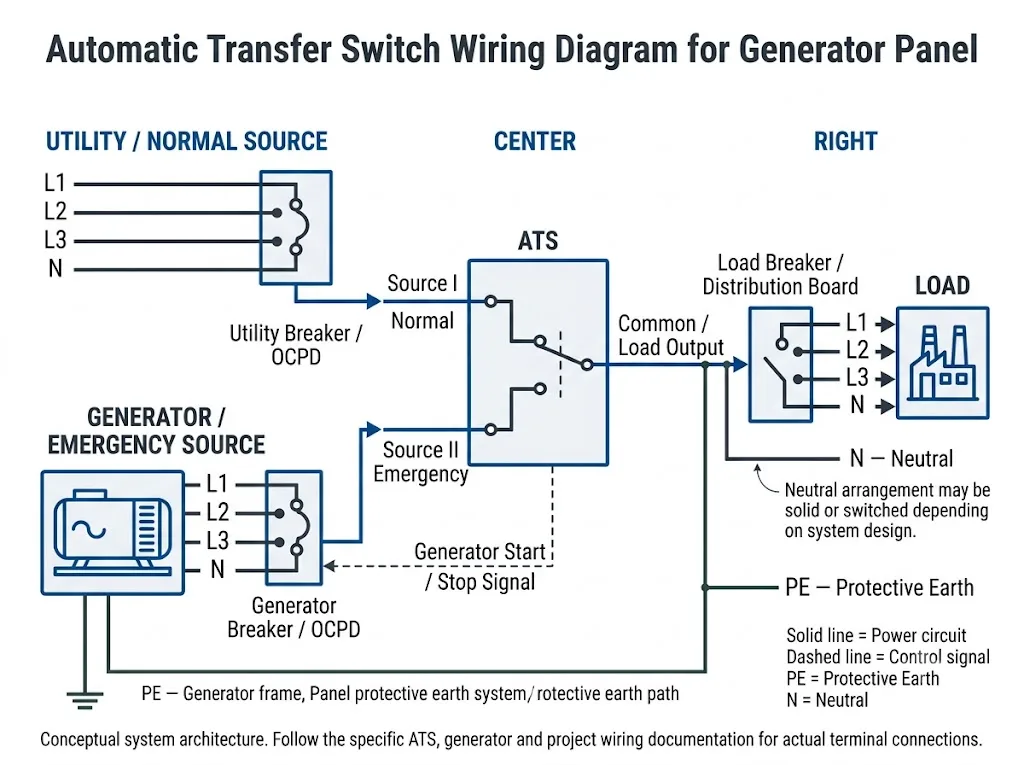
Identify the Three Power Sides Before Wiring
Before looking at terminal numbers, identify the function of every power connection. This is more reliable than assuming that the physical position of a terminal tells you whether it is the normal source, emergency source or load.
- Normal / Utility source: the preferred supply connects to the ATS Normal, Source I or equivalent source terminals.
- Emergency / Generator source: generator output connects to the second source side through the protection and isolation arrangement required by the project.
- Common / Load output: the ATS output feeds the downstream distribution board, load bus or equipment circuit.
Makna rekayasa: “Normal”, “Emergency”, “Source I”, “Source II” and “Load” describe functions. Their physical terminal locations are not universal. Never copy terminal positions or terminal numbers from another ATS model.
Utility / Normal Source Input
The normal source is normally the preferred utility or mains source. The ATS controller monitors the source conditions required by its control logic. Depending on the controller, these functions can include undervoltage, overvoltage, phase loss, voltage unbalance, frequency and incorrect phase sequence detection.[4]
For a three-phase generator panel, the project team should therefore confirm system voltage, frequency, phase arrangement and the sensing functions actually provided by the selected ATS rather than assuming every controller monitors the same conditions.
Generator / Emergency Source Input
The emergency source receives the generator output. Generator power conductors belong to the power circuit; they are different from the much smaller control conductors used to request generator start.
In a typical automatic sequence, the ATS detects an unacceptable normal source, requests generator start, waits until the emergency source satisfies the controller's acceptance criteria and then transfers the load according to the programmed sequence.[5]
Common / Load Output
The common ATS output supplies the downstream load. Depending on the project, it may feed a distribution board, essential-load bus, control panel or another downstream protective device.
The ATS performs source transfer. Do not assume that it replaces every breaker, fuse or other required protective device. Short-circuit protection, conductor sizing, selectivity and equipment ratings must be coordinated for the actual system.
How Do Generic Diagram Labels Map to a Real ATS?
A generic ATS wiring diagram explains system relationships. The next engineering task is to map those functions to the documentation for the exact switch and controller being supplied.
| Generic Function | What to Find on the Actual ATS | Apa yang Harus Dikonfirmasi |
|---|---|---|
| Normal / Source I | Preferred-source power terminals | Terminal identity, voltage, phase sequence and source priority |
| Emergency / Source II | Alternative-source power terminals | Generator voltage, phase arrangement and source acceptance settings |
| Common / Load | Load-side terminals | Load connection, current rating and downstream protection |
| Neutral | Neutral terminal, solid-neutral bar or switched-neutral pole | Grounding, bonding and project neutral arrangement |
| Generator Start | Start/stop relay or controller output | COM/NO/NC logic, contact rating and generator-controller interface |
| Source Sensing | Internal sensing or dedicated sensing connections | Monitored parameters, voltage range and model-specific wiring |
| Control Power | Internal or external controller supply arrangement | Voltage, source, polarity where relevant and manufacturer requirements |
| Auxiliary I/O | Auxiliary or programmable input/output terminals | Actual status, alarm, test, BMS or PLC function required |
Aturan utama: functional concepts can be transferred from a generic diagram; terminal numbers cannot. Always use the wiring diagram supplied for the exact ATS model and controller.
2P, 3P and 4P ATS Wiring: What the Pole Count Really Means
Pole count tells you how many current paths are switched. It does melakukan by itself tell you the grounding system or whether a particular conductor must be neutral.
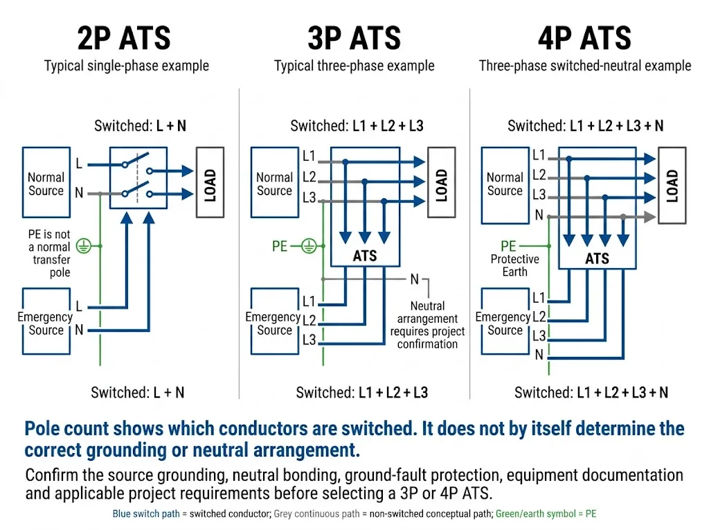
| Konfigurasi | Apa yang Disampaikan Kepada Anda | Contoh Tipikal | Must Be Confirmed |
|---|---|---|---|
| 2P | Two current paths are switched | L + N in some 230 V single-phase systems, or L1 + L2 in some 120/240 V single-phase systems | Actual conductor arrangement and neutral treatment |
| 3P | Three current paths are switched | L1 + L2 + L3 in a three-phase system | Neutral arrangement if the system includes N |
| 4P | Four current paths are switched | L1 + L2 + L3 + N in a switched-neutral three-phase system | Grounding, bonding, neutral switching and project requirements |
Kesimpulan pengadaan: “2P”, “3P” or “4P” is not enough information for an OEM panel order. Supply the system drawing and state which conductors the project requires the ATS to switch.
A 2-Pole ATS Does Not Always Mean L + N
A 2P ATS simply has two switched current paths. In a 230 V line-to-neutral application, the two poles may be used for line and neutral. In other systems, including some 120/240 V single-phase arrangements, the two switched poles may be line conductors while neutral remains on a separate solid-neutral connection.[7]
Never infer neutral treatment only from the label “2P”. Confirm the actual ATS construction and project wiring.
How Should Neutral Be Handled?
Neutral is one of the most important ATS project decisions. Schneider Electric / ASCO documentation distinguishes solid-neutral and switched-neutral configurations and explains that the choice is connected to the grounding arrangement of the normal and alternative sources.[3]
Solid Neutral
In a solid-neutral arrangement, neutral is not transferred by a dedicated ATS switching pole. The system neutral remains connected through the designed neutral path.
This should not be created by simply adding an arbitrary jumper. The neutral path must be coordinated with generator grounding, source bonding and the protection scheme.
Switched Neutral
In a switched-neutral arrangement, the load neutral transfers between the normal and emergency sources through a dedicated switching pole. This is one reason 4P ATS equipment is used in some three-phase four-wire generator installations.[3]
A 4P ATS is not automatically better than a 3P ATS. The correct choice depends on grounding and bonding design, protection method, equipment documentation and applicable project requirements.
Do not copy neutral or N-PE bonding from a generic internet diagram. The correct arrangement can change with source grounding, generator design, ground-fault protection, installation rules and the approved project single-line diagram.
How Should Protective Earth (PE) Be Handled?
PE and neutral perform different functions. IEC 60364-5-54 addresses earthing arrangements, protective conductors and protective bonding conductors used for the safety of low-voltage installations.[2]
A conceptual ATS diagram should therefore show PE as part of the protective conductor and bonding system rather than as another ordinary transfer pole.
The final PE, bonding and generator-frame connections must follow the actual project earthing design.
Generator Start Signal and ATS Control Wiring
Generator start wiring is not generator power wiring. Generator power conductors supply the ATS emergency source. The start circuit carries a control command between the ATS controller and generator controller.
Cummins transfer-switch guidance describes a typical utility-to-generator sequence as source monitoring, generator start, generator voltage and frequency build-up, transfer, retransfer after normal power returns and generator stop after the relevant delay.[5]
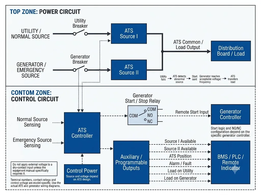
Generator Start / Stop Interface
Many generator-oriented ATS controllers provide a relay or equivalent interface for starting and stopping the generator. Depending on the equipment, relay contacts may be identified by functions such as COM, NO and NC.
Do not assume that the same contact state starts every generator. Before the panel schematic is approved, confirm:
- whether the generator controller expects a dry contact, powered signal or another interface;
- which contact state requests generator start;
- the permitted contact voltage and current;
- whether the command remains active while the generator runs;
- the exact remote-start input specified by the generator manufacturer.
Source Sensing: What Does the ATS Actually Monitor?
An ATS needs information about its sources before it can make a transfer decision. Depending on the controller, monitored conditions can include no voltage, undervoltage, overvoltage, phase loss, voltage unbalance, invalid frequency and incorrect phase sequence. ABB TruONE controller documentation lists these types of source-failure detection functions, but availability varies by controller level and model.[4]
Source sensing may be integrated into the ATS or may require model-specific connections. A generic wiring diagram should explain the function without inventing terminal numbers.
Makna rekayasa: if the project requires specific undervoltage, frequency, phase-loss or phase-sequence behaviour, include that requirement in the ATS specification instead of assuming every controller provides the same monitoring logic.
Control Power
Do not assume every ATS needs the same external control voltage. ATS designs differ. Some controllers derive operating power from the connected sources, while other platforms provide or accept auxiliary control-power options.[4]
The actual product manual must define the control-power source, voltage and connection method.
Auxiliary Contacts, Dry Contacts and Remote Indication
Depending on the controller, auxiliary or programmable I/O can support source status, switch position, alarms, generator exercising, load-shedding logic or remote monitoring. ABB TruONE documentation, for example, identifies auxiliary position contacts and programmable digital I/O on applicable controller levels.[4]
For BMS or PLC integration, define the required function instead of writing only “dry contact required”. Useful project descriptions include:
- Normal source available
- Emergency source available
- Load on normal source
- Load on generator
- ATS position indication
- ATS alarm or fault indication
- Remote test or inhibit input, if required
Makna pembeli: request the controller I/O table together with the ATS wiring diagram before approving the control schematic. “Auxiliary contact” can describe several different functions.
ATS and Circuit Breakers: They Do Different Jobs
The ATS transfers a load between sources. Breakers, fuses and other protective devices perform protection and isolation functions defined by the complete system design.
For a generator panel, confirm the source-side protective devices, load-side arrangement where applicable, prospective short-circuit conditions, ATS ratings and coordination requirements against the selected equipment documentation.
IEC 60947-6-1:2026 applies to transfer switching equipment, including automatic transfer switching equipment and stand-alone ATS controllers.[1]
Common ATS Wiring Mistakes
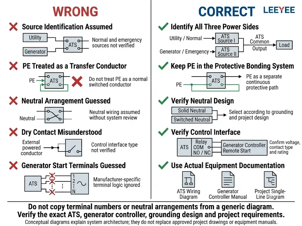
1. Normal and Emergency Sources Are Misidentified
The ATS may use Normal/Emergency, Source I/Source II, Source A/Source B or another manufacturer convention. Identify the function from the manual, not only from terminal position.
2. Load Is Connected to a Source Terminal
The common load output must be distinguished from both source inputs before panel production or commissioning.
3. “2P” Is Automatically Interpreted as L + N
Two poles means two switched current paths. The conductors assigned to those paths depend on the actual system. Some 2P transfer-switch designs use a separate solid neutral.[7]
4. Neutral Is Selected Only by Counting Phases
A three-phase system does not by itself determine whether neutral should be solid or switched. The grounding and bonding architecture must also be reviewed.[3]
5. PE Is Treated as a Normal Transfer Conductor
Protective earth belongs to the installation's protective conductor system. Its continuity and bonding arrangement must follow the approved earthing design.[2]
6. Generator Start Terminals Are Guessed
COM, NO, NC, control voltage and terminal numbers are product-specific. The ATS manual and generator-controller manual must agree before the control circuit is approved.
7. A Dry Contact Is Treated as a Universal Powered Output
A dry contact is not automatically a control-voltage source. Verify the exact interface, permitted voltage and contact rating before connecting a generator controller, PLC or BMS.
8. Source Sensing Is Assumed Instead of Specified
If the project requires particular voltage, frequency, phase-loss or phase-sequence behaviour, verify that the chosen controller provides it and confirm the required settings or sensing connections.[4]
What Should Be Checked Before the ATS Panel Is Approved?
The following is an engineering review checklist, not a live-work procedure. Actual testing and commissioning must be performed under the approved project method by appropriately qualified personnel.
Generator ATS Panel Review Checklist
- Normal source identity confirmed
- Emergency source identity confirmed
- Common load output confirmed
- System voltage verified
- System frequency verified
- Phase arrangement confirmed
- Required pole count confirmed
- Neutral scheme confirmed
- PE and bonding design confirmed
- Source protection coordinated
- ATS short-circuit data reviewed
- Generator start interface verified
- Control-power arrangement verified
- Source sensing functions verified
- Auxiliary I/O functions verified
- Normal-to-generator sequence reviewed
- Retransfer sequence reviewed
- Remote indication requirements confirmed
- Manufacturer drawings included in project file
What Should a Buyer Send Before Ordering a Generator ATS Panel?
A request such as “3-phase 100 A ATS” is not enough to confirm a wiring architecture. The supplier needs enough information to understand both the power circuit and control circuit.
Before Ordering / OEM Information
- Project single-line diagram
- Utility system voltage
- Generator output voltage
- 50 Hz or 60 Hz
- Satu fase atau tiga fase
- Wire system: 2-wire, 3-wire or 4-wire as applicable
- Earthing / grounding arrangement
- Required neutral arrangement
- Arus beban terukur
- Prospective fault level where required
- Source-side breaker information
- Model pengendali generator
- Remote-start interface requirement
- Required ATS status contacts
- PLC or BMS interface requirements
- Control-power requirements
- Fungsi pendeteksian sumber yang diperlukan
- Automatic / manual operation requirements
- Required standard or approval documents
- Panel dimensions and installation constraints
- OEM label or documentation requirements
For projects using IEC-based transfer switching equipment, confirm the applicable product standard and project requirements. IEC 60947-6-1:2026 is the current fourth edition for transfer switching equipment.[1]
Untuk proyek-proyek di Amerika Utara, UL Solutions mengidentifikasi UL 1008 for automatic transfer switches used in emergency and optional standby systems. Applicability and certification scope must be confirmed for the actual product and project.[6]
Need to Confirm an ATS Wiring Configuration?
Send your single-line diagram, source voltages, phase and wire arrangement, neutral requirement, rated current, generator-controller information and required control signals. LEEYEE can use those project details as the basis for configuration discussion before model approval.
Pertanyaan yang Sering Diajukan
Where do the utility, generator and load wires connect on an ATS?
Conceptually, utility connects to the Normal or Source I side, the generator connects to the Emergency or Source II side, and the common ATS output supplies the load. Physical terminal positions and terminal names vary by product, so the exact manufacturer wiring diagram must be used.
Does a 2P ATS always switch line and neutral?
No. Two poles only means that two current paths are switched. In some 230 V single-phase systems they may be L and N. In some 120/240 V single-phase transfer-switch systems the two switched poles are line conductors and neutral can remain solid. Confirm the actual ATS construction and system design.[7]
Does a three-phase generator always need a 4P ATS?
No. A 4P ATS can switch L1, L2, L3 and neutral, while a 3P ATS switches three current paths. Whether the project needs switched neutral depends on grounding, bonding, protection and the applicable system design.[3]
What is the difference between ATS power wiring and generator-start wiring?
Power wiring carries the generator output to the emergency source side of the ATS. Generator-start wiring is a control interface between the ATS controller and generator controller. The exact start interface is equipment-specific.[5]
What does an ATS monitor before transferring to the generator?
It depends on the controller. Available sensing functions can include voltage, frequency, phase loss, voltage unbalance and phase sequence. The selected controller and project settings determine which conditions are actually used.[4]
Can I use generator-start terminal numbers shown in another ATS diagram?
No. Generic diagrams can explain function, but terminal numbering, NO/NC logic, control voltage and contact ratings are model-specific. Use the documentation for both the selected ATS and generator controller.
Should protective earth pass through the ATS?
PE should not be treated as an ordinary load-transfer pole in a generic ATS diagram. Protective conductors and bonding belong to the installation earthing system and must follow the approved grounding design and applicable requirements.[2]
Does an ATS replace the utility and generator breakers?
Do not assume so. Source transfer and circuit protection are different functions. The required breakers, fuses, short-circuit ratings and coordination depend on the selected ATS and complete system design.
What information should I send for an ATS wiring review?
Send the single-line diagram, utility and generator voltages, phase and wire arrangement, grounding system, neutral requirement, rated current, generator-controller model, breaker information and required start, status, BMS or PLC signals.
Referensi
- IEC. IEC 60947-6-1:2026, Low-voltage switchgear and controlgear – Part 6-1: Multiple function equipment – Transfer switching equipment. Halaman publikasi resmi IEC.
- IEC. IEC 60364-5-54:2011+A1:2021, Instalasi listrik tegangan rendah – Bagian 5-54: Pemilihan dan pemasangan peralatan listrik – Pengaturan pembumian dan konduktor pelindung. Halaman publikasi resmi IEC.
- Schneider Electric / ASCO. Neutral Configurations in Transfer Switches, Document ASC-DB-NCTS. Official document page.
- ABB. TruONE Automatic Transfer Switches – Product and Controller Documentation. ABB Library document.
- Cummins. Application Manual – Transfer Switches. Cummins application manual.
- UL Solutions. Layanan Sertifikasi dan Evaluasi Switch. UL Solutions official page.
- Eaton. Automatic Transfer Switch, Bypass Isolation, Contactor Type – Operation and Maintenance Manual, IB140021EN. Eaton official manual.
These references support general transfer-switch principles, standards and manufacturer-specific examples. A configuration shown by one manufacturer must not be assumed to apply to another ATS model. Project drawings and selected equipment documentation remain the basis for final wiring approval.
