
La selezione di un dispositivo di protezione contro le sovratensioni (SPD) in corrente alternata per un quadro di distribuzione principale non è una semplice questione di scegliere il valore di kA più elevato. La corretta soluzione di protezione contro le sovratensioni per MDB dipende dai punti di ingresso della corrente di fulmine, dal sistema di messa a terra, dalle modalità di protezione richieste, dalla tensione operativa, dalla corrente di cortocircuito disponibile e dalle apparecchiature situate a valle.
Questa guida è destinata ai produttori di quadri elettrici, agli installatori elettrici, ai consulenti, ai team di approvvigionamento di progetto e agli acquirenti OEM che devono approvare una configurazione SPD in corrente alternata prima della produzione del quadro o dell'installazione in loco.
Indice dei contenuti
Risposta Veloce
Utilizzare un SPD di Tipo 1 all'origine quando l'impianto può essere soggetto a correnti parziali di fulmine, come nel caso di un edificio dotato di un sistema di protezione esterna contro i fulmini o in altre condizioni accertate di esposizione diretta alla corrente di fulmine.
Utilizzare un SPD di Tipo 2 quando il quadro principale (MDB) richiede protezione contro sovratensioni indotte o di manovra, ma la valutazione del progetto non richiede la capacità di scarica di fulmini di Tipo 1.
Utilizzare un SPD testato di Tipo 1+2 quando il quadro principale richiede prestazioni sia di scarica di fulmini che di limitazione di tensione in un unico dispositivo coordinato.
Dopo aver selezionato il tipo di SPD, confermare il sistema di messa a terra, le modalità di protezione, Uc, Iimp, In, Imax, Up, il comportamento in caso di sovratensione temporanea, la capacità di cortocircuito, la protezione di riserva e i requisiti di segnalazione remota. Il modello finale deve essere approvato in base allo schema unifilare e ai dati di installazione del produttore dell'SPD, non esclusivamente dall'etichetta del prodotto. [1] [2] [3]
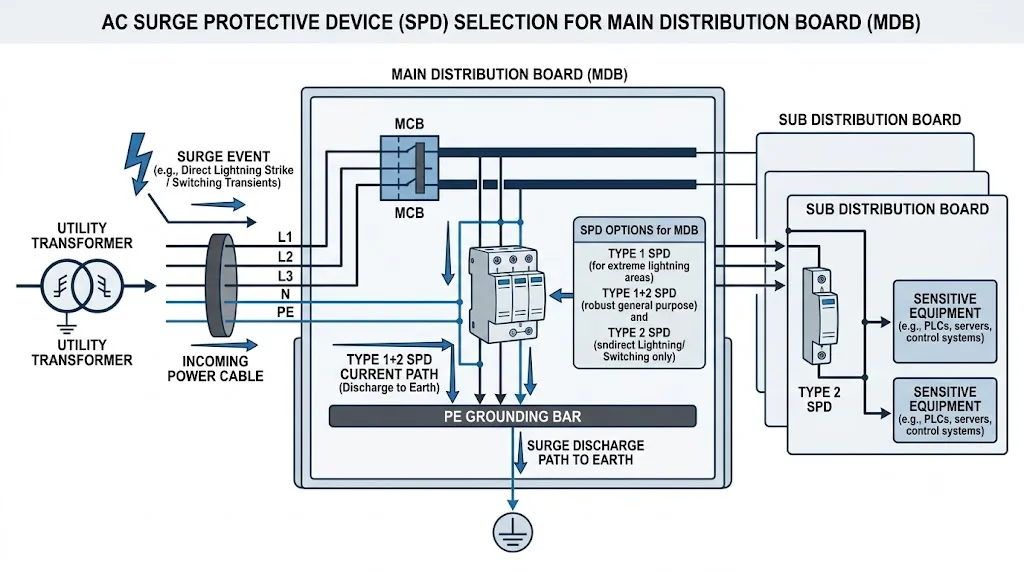
Perché l'MDB rappresenta un punto critico per la protezione dalle sovratensioni
Il quadro di distribuzione principale è solitamente situato in corrispondenza o in prossimità dell'origine dell'alimentazione dell'impianto a bassa tensione. Una sovratensione che penetra in questo punto può propagarsi attraverso diversi circuiti in uscita prima di raggiungere sistemi di controllo, azionamenti, apparecchiature di comunicazione e altri carichi sensibili.
L'installazione di un SPD nel quadro principale (MDB) costituisce il primo stadio di limitazione delle sovratensioni. Ciò non completa automaticamente il progetto di protezione. Quando le apparecchiature a valle sono distanti, presentano un livello di tenuta all'impulso inferiore o richiedono una tensione residua più bassa, potrebbe essere necessaria un'ulteriore protezione coordinata di Tipo 2 o Tipo 3. [3] [5]
Tabella decisionale per la selezione degli SPD AC per MDB
Utilizzare la seguente tabella come strumento di screening tecnico. Essa fornisce un orientamento nella selezione, non sostituisce la valutazione del rischio di fulminazione, le normative locali sugli impianti elettrici o l'approvazione del progetto.
| Condizioni del quadro elettrico principale (MDB) | Direzione di selezione | Cosa deve essere confermato |
|---|---|---|
| È installato un sistema di protezione esterna contro i fulmini | Valutare un SPD di Tipo 1 o un SPD di Tipo 1+2 testato all'origine dell'alimentazione. | Classe LPS, distribuzione prevista della corrente di fulmine, configurazione dell'alimentazione, Iimp richiesto e coordinamento con gli SPD a valle. |
| È stata identificata un'alimentazione aerea in ingresso o un'altra esposizione diretta alla corrente di fulminazione. | Potrebbe essere richiesta una capacità di Tipo 1. | Valutazione del rischio, normative di installazione locali ed eventuale ingresso di correnti parziali di fulminazione nel quadro. |
| Non è stata identificata alcuna condizione di Tipo 1, ma è necessaria una protezione contro le sovratensioni all'origine. | Un SPD di Tipo 2 potrebbe essere idoneo. | Sistema di alimentazione, Uc, Up, In, Imax, livello di tenuta dell'apparecchiatura protetta e protezione di riserva. |
| Un singolo dispositivo deve garantire prestazioni sia di Tipo 1 che di Tipo 2. | Utilizzare un dispositivo testato e dichiarato come Tipo 1+2. | Non dare per scontato che qualsiasi prodotto di Tipo 1 fornisca il livello di protezione di Tipo 2 richiesto. Verificare i dati di test dichiarati completi. |
| Le apparecchiature elettroniche critiche sono collegate molto a valle | Coordinare l'SPD nel quadro principale (MDB) con un'ulteriore protezione a valle. | Percorso dei cavi, distanza di separazione, tenuta all'impulso dell'apparecchiatura, tensione Up ai morsetti dell'apparecchiatura e guida al coordinamento con il produttore. |
Conclusione per gli acquisti: lo stesso quadro di distribuzione principale (MDB) da 400/230 V può richiedere diversi tipi di SPD quando l'esposizione ai fulmini, l'ingresso di alimentazione e i requisiti di protezione a valle sono differenti.
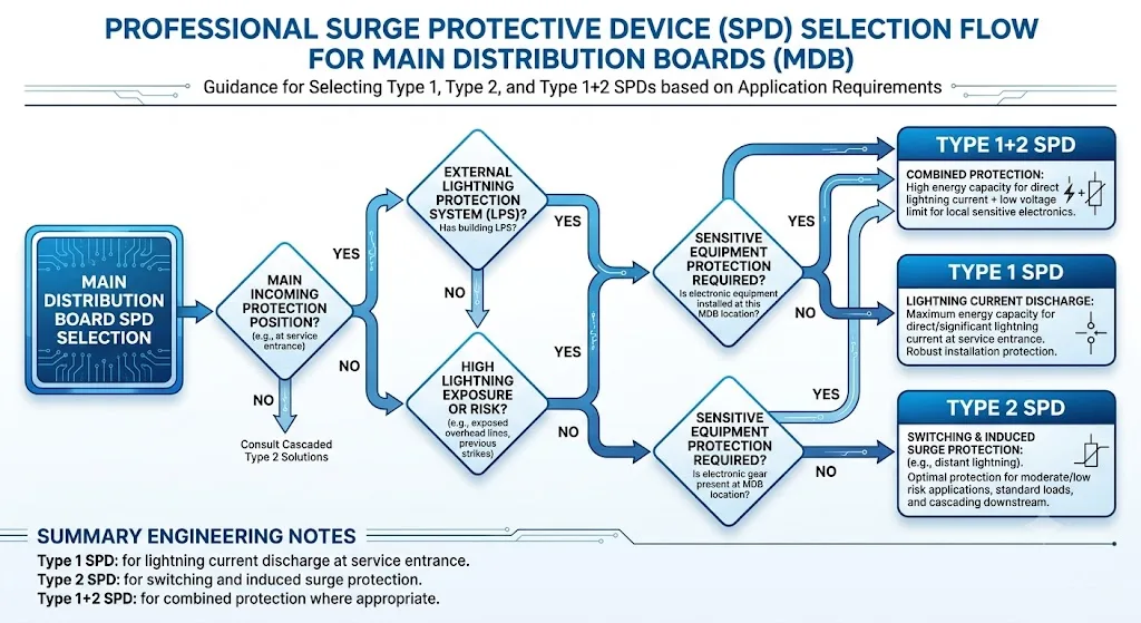
Come scegliere tra Tipo 1, Tipo 2 o Tipo 1+2
Tipo 1: Quando la corrente di fulmine può entrare nel quadro MDB
Gli SPD di Tipo 1 sono testati con una corrente d'impulso di fulmine 10/350 µs. Vengono selezionati laddove il dispositivo potrebbe dover condurre una corrente di fulmine parziale all'origine dell'impianto. [1] [2]
Un edificio con un sistema di protezione dai fulmini esterno è un motivo comune per valutare la protezione di Tipo 1 nel quadro MDB. La corrente Iimp richiesta dovrebbe derivare dal progetto di protezione dai fulmini e dalla distribuzione della corrente, non copiata da un altro progetto.
Tipo 2: Quando il requisito principale è la limitazione delle sovratensioni transitorie
Gli SPD di Tipo 2 sono testati con una forma d'onda di corrente 8/20 µs e sono comunemente usati per limitare le sovratensioni indotte da fulmini e le sovratensioni di manovra. Un dispositivo di Tipo 2 può essere idoneo nel quadro MDB quando la valutazione dell'impianto non richiede la capacità di gestire correnti di fulmine di Tipo 1. [1] [5]
La parola “principale” nel quadro di distribuzione principale non significa automaticamente che ogni progetto necessiti di un Tipo 1. La decisione dipende dalla probabilità che in quella posizione giunga una corrente di fulmine parziale.
Tipo 1+2: Prestazioni combinate in un unico dispositivo testato
Un SPD di Tipo 1+2 presenta prestazioni dichiarate per entrambe le classi di prova. Viene spesso utilizzato nel quadro principale (MDB) quando il progetto richiede la scarica di correnti di fulmine e un livello di protezione di tensione inferiore in un'unica unità.
Tipo 1+2 non significa che il coordinamento a valle possa sempre essere omesso. La tensione finale sulle apparecchiature sensibili è influenzata dal valore Up dell'SPD, dall'induttanza dei conduttori, dalla disposizione dell'installazione, dalla distanza dei cavi e da eventuali stadi di protezione aggiuntivi. [3] [6]
Non effettuare la selezione basandosi esclusivamente sulla marcatura del tipo
Due SPD contrassegnati come Tipo 1+2 possono avere valori diversi di Uc, Iimp, In, Up, comportamento in cortocircuito, modalità di protezione, larghezza del modulo e requisiti di protezione di riserva. È necessario confrontare la scheda tecnica completa e le condizioni di progetto.
Come valutare le configurazioni 3P, 4P e 3P+N
Le etichette dei poli non sono sempre utilizzate in modo coerente tra i fornitori. "4P" può descrivere quattro moduli, quattro terminali o uno specifico circuito di protezione. "3P+N" può riferirsi a una configurazione trifase con un elemento di protezione dedicato tra neutro e terra. L'acquirente deve quindi verificare le modalità di protezione interne e lo schema elettrico invece di approvare il modello basandosi solo sul nome del polo.
| Descrizione di mercato | Cosa può descrivere | Domanda di approvazione |
|---|---|---|
| 3P | Tre percorsi di protezione riferiti alla fase, spesso utilizzati in assenza di un conduttore di neutro separato nel punto di installazione. | Il sistema è TN-C prima della separazione del PEN, o la protezione del neutro viene omessa per un altro motivo documentato? |
| 4P or 4+0 | Quattro percorsi di protezione simili che coinvolgono L1, L2, L3 e N, comunemente collegati verso PE secondo il circuito dichiarato. | Quali sono le esatte modalità di protezione L-PE, N-PE o L-N e sono idonee per il sistema di messa a terra e le condizioni di sovratensione temporanea? |
| 3P+N or 3+1 | Tre percorsi di protezione L-N più un elemento dedicato N-PE, spesso con una tecnologia diversa dai moduli di fase. | L'elemento N-PE è correttamente dimensionato per la corrente di scarica totale, la corrente susseguente e la configurazione TT o TN-S selezionata? |
Conclusione per l'approvvigionamento: specificare il circuito di protezione richiesto, non solo "3P", "4P" o "3P+N" nell'ordine di acquisto.
Differenze tra i sistemi TT, TN-S e TN-C-S
La configurazione di messa a terra determina quali conduttori sono presenti nel quadro di distribuzione principale (MDB) e come deve essere deviata la corrente di sovratensione. Modifica inoltre le condizioni di sovratensione temporanea a cui l'SPD potrebbe essere sottoposto.
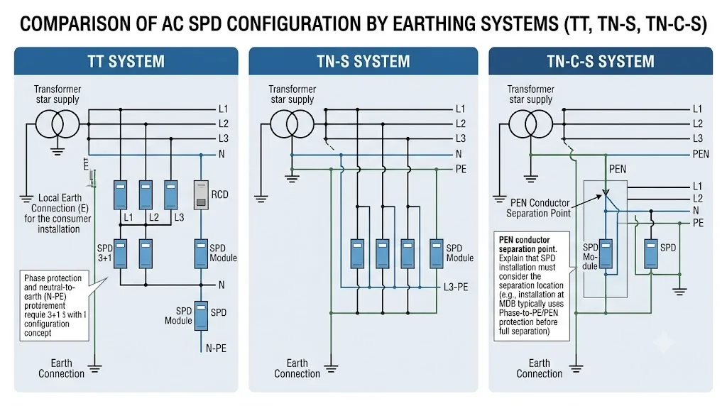
Sistema TT
In un sistema TT, la terra di protezione dell'impianto non è lo stesso conduttore del neutro di alimentazione. Una configurazione 3+1, con protezione fase-neutro e un elemento dedicato neutro-terra, viene comunemente valutata perché può fornire un percorso di scarica N-PE definito, affrontando al contempo le considerazioni sulle sovratensioni temporanee dei sistemi TT.
Questa non è un'istruzione universale per utilizzare ogni prodotto commercializzato come "3+1". L'elemento N-PE, i valori di Uc, le modalità di protezione, la configurazione di disconnessione e le prestazioni TOV devono essere tutti conformi al progetto e alle norme di installazione locali. [3] [6]
Sistema TN-S
In un sistema TN-S, il neutro e la terra di protezione sono separati lungo tutta la parte rilevante dell'impianto. La soluzione per l'MDB può utilizzare una configurazione a quattro percorsi o un circuito 3+1, a seconda del concetto di protezione e del cablaggio dichiarato dal produttore.
La scelta corretta è determinata dalle modalità di protezione, Uc, comportamento TOV, Up e dal coordinamento del sistema. "TN-S significa 4P" è troppo generico per essere usato come regola di approvazione.
Sistema TN-C-S
Un'installazione TN-C-S utilizza un conduttore PEN a monte e conduttori N e PE separati dopo il punto di separazione. La configurazione dell'SPD dipende dal fatto che sia installato prima o dopo tale punto.
Prima della separazione del PEN, le condizioni di installazione assomigliano al sistema TN-C. Dopo la separazione, i conduttori protetti assomigliano al sistema TN-S. Il fornitore deve ricevere lo schema unifilare e la posizione esatta dell'SPD per evitare un collegamento errato del neutro o della terra.
Confine critico di cablaggio
Non approvare mai una configurazione SPD TN-C-S senza aver identificato il punto di separazione del PEN. Un presupposto errato può creare un percorso di protezione sbagliato o un collegamento N-PE inaccettabile.
Quali parametri deve confermare un acquirente di MDB?
I seguenti parametri rispondono a diverse questioni ingegneristiche. Nessuno di essi deve essere utilizzato da solo come prova che un SPD sia migliore di un altro.
| Parametro | Cosa significa | Cosa deve confermare l'acquirente |
|---|---|---|
| Uc | Tensione massima di funzionamento continuativo per la modalità di protezione dichiarata. | Tensione nominale, tensione massima di funzionamento normale, sistema di messa a terra, tolleranza di tensione e condizioni TOV. |
| Iimp | Capacità di corrente impulsiva da fulmine utilizzata per la classificazione di Tipo 1, testata con una forma d'onda 10/350 µs. | Valore richiesto per polo o modalità, distribuzione totale della corrente e base di progettazione della protezione contro i fulmini. |
| In | Corrente di scarica nominale, generalmente associata a test ripetuti 8/20 µs. | Prestazioni di Tipo 2 dichiarate e se la classificazione si applica per modalità o per modulo. |
| Imax | Corrente di scarica massima dichiarata per un evento 8/20 µs secondo il metodo di prova applicabile. | Non utilizzare Imax da solo. Confrontare In, Up, Uc, classe di prova e prestazioni in cortocircuito. |
| Su | Livello di protezione della tensione dichiarato durante i test di sovratensione. | Tensione di tenuta all'impulso dell'apparecchiatura, lunghezza dei cavi e livello di protezione risultante ai terminali dell'apparecchiatura stessa. |
| TOV | Comportamento sotto una sovratensione temporanea a frequenza industriale invece di un breve impulso di sovratensione. | Guasti del sistema di messa a terra, condizioni del neutro e se l'SPD resiste o fallisce in sicurezza secondo il test dichiarato. |
| SCCR o tenuta al cortocircuito | La capacità dell'SPD di essere applicato in sicurezza in un punto con una corrente di cortocircuito presunta specificata in condizioni di protezione dichiarate. | Corrente di guasto presunta all'MDB, fusibile o interruttore richiesto e ambito del certificato per la combinazione completa. |
Conclusione per l'approvvigionamento: un valore Imax elevato non compensa un Uc inadatto, un Up eccessivo, la mancanza di una classificazione di Tipo 1 o un coordinamento del cortocircuito inadeguato.
Flusso di lavoro in otto fasi per la selezione di un progetto MDB
- Confermare i dati di alimentazione. Registrare la tensione nominale fase-fase e fase-neutro, la frequenza e la tensione massima di funzionamento normale.
- Identificare la configurazione di messa a terra nel punto esatto dell'SPD. Indicare TT, TN-S, TN-C o TN-C-S e contrassegnare il punto di separazione del PEN ove applicabile.
- Determinare se è richiesta la funzionalità di Tipo 1. Revisionare l'LPS esterno, l'alimentazione aerea, la valutazione del rischio di fulminazione e la possibilità che una corrente parziale di fulmine entri nell'impianto.
- Definire il circuito di protezione. Specificare le modalità richieste L-N, L-PE, N-PE o L-PEN invece di fare affidamento esclusivamente sulla terminologia 3P, 4P o 3+1.
- Selezionare i parametri relativi alla tensione. Confermare Uc, comportamento TOV e Up rispetto al sistema reale e alle apparecchiature protette.
- Confermare le prestazioni della corrente di scarica. Verificare Iimp per il Tipo 1 e In/Imax per il Tipo 2 in base ai requisiti del progetto.
- Coordinare la protezione contro il cortocircuito e la protezione di backup. Confrontare la corrente di cortocircuito presunta del quadro principale (MDB), il dispositivo di protezione a monte e i dati relativi al fusibile di backup massimo o all'interruttore automatico approvato dal produttore.
- Approvare l'installazione e la documentazione. Verificare lunghezza del collegamento, percorso del conduttore, spazio sulla guida DIN, contatto remoto, modulo di ricambio, schema elettrico, scheda tecnica e campo di applicazione del certificato specifico del modello.
Tre scenari realistici di selezione MDB
Scenario 1: MDB commerciale, 400/230 V TN-S, nessun LPS esterno
Uno scaricatore (SPD) di Tipo 2 può essere idoneo quando la valutazione del progetto non identifica correnti parziali di fulmine all'origine dell'alimentazione. Il progettista deve comunque verificare il circuito di protezione, Uc, Up, In, Imax, la corrente di cortocircuito e i requisiti delle apparecchiature a valle.
Limite di selezione: l'assenza di un LPS esterno non dimostra di per sé che il Tipo 1 non sia necessario. È necessario valutare anche l'alimentazione aerea e altre condizioni di esposizione.
Scenario 2: MDB industriale, TN-C-S, LPS esterno installato
All'origine dell'impianto deve essere valutata una protezione di Tipo 1 o di Tipo 1+2. Il progettista deve identificare se lo scaricatore si trova prima o dopo la separazione PEN e calcolare o specificare la Iimp richiesta in base al concetto di protezione dai fulmini.
Limite di selezione: non copiare automaticamente 12,5 kA o 25 kA per polo da un altro progetto. La classe LPS, la distribuzione della corrente e la configurazione del sistema possono modificare il requisito.
Scenario 3: Quadro principale TT trifase a servizio di controlli sensibili
Viene comunemente valutato un circuito di protezione 3+1, con moduli fase-neutro e un elemento N-PE dedicato. Il modello finale deve essere verificato per Uc, TOV, capacità di scarica totale N-PE, Up e coordinamento con gli SPD del quadro di controllo a valle.
Limite di selezione: la dicitura “3P+N” su un preventivo non è sufficiente. Richiedere lo schema elettrico e le specifiche dichiarate per ogni modalità di protezione.
Fusibile di backup o interruttore magnetotermico (MCB): come verificarlo
Il sezionatore termico interno dello scaricatore non sostituisce automaticamente la protezione di backup esterna contro il cortocircuito. Il suo scopo e le sue condizioni operative sono differenti.
Il fusibile o l'interruttore automatico esterno richiesto dipende dal design dello scaricatore, dalla corrente di cortocircuito presunta, dal dispositivo di protezione a monte e dal coordinamento testato dal produttore. Alcuni scaricatori includono una protezione di backup integrata. Altri specificano un fusibile di backup massimo ammissibile o una caratteristica di interruttore approvata. [3] [5]
Informazioni richieste per l'approvazione della protezione di backup
- Corrente di cortocircuito presunta nel punto di installazione dell'MDB
- Tipo e corrente nominale del fusibile o dell'interruttore a monte
- Dati del fusibile di backup massimo dello scaricatore o dell'interruttore automatico approvato
- Discriminazione o selettività richiesta con la protezione a monte
- Corrente di cortocircuito nominale (SCCR) dello scaricatore in base all'assetto di protezione dichiarato
- Sezione del conduttore e capacità dei terminali
Posizione di installazione e lunghezza del collegamento
Uno scaricatore per MDB viene solitamente collegato vicino alla sezione di ingresso, vicino al sezionatore di ingresso o al punto di connessione in uscita più adatto consentito dal design del quadro. L'obiettivo è creare un percorso breve e diretto dai conduttori in tensione attraverso lo scaricatore verso il PE o PEN.
I conduttori lunghi aggiungono tensione induttiva durante una sovratensione rapida. Questa tensione aggiuntiva appare in serie con il valore Up dichiarato dello scaricatore e può aumentare in modo significativo la tensione che raggiunge l'apparecchiatura.
Le linee guida applicative basate su IEC solitamente mirano a un percorso di collegamento combinato conduttore attivo-scaricatore e scaricatore-PE/PEN di non oltre circa 0,5 m, ove la configurazione di installazione selezionata lo consenta. Le norme locali, la costruzione del quadro e le istruzioni del produttore rimangono l'autorità finale. [3] [5]
Errore comune nella disposizione del quadro
Installare lo scaricatore in uno spazio libero sulla guida DIN lontano dalla barra collettrice di ingresso può comportare cavi di fase e di terra lunghi. Il prodotto potrebbe avere un valore Up dichiarato basso, ma il percorso installato completo può fornire una tensione residua molto più elevata.
Quando è opportuno specificare un contatto di segnalazione remoto?
La segnalazione remota è utile quando l'MDB è incustodito, difficile da ispezionare o collegato a un sistema di gestione dell'edificio, SCADA o di manutenzione. Un contatto di commutazione a potenziale zero può segnalare lo stato dello scaricatore senza richiedere che un tecnico apra il quadro per ogni ispezione.
Non è obbligatorio per ogni MDB. Il progetto dovrebbe confermare la logica del contatto, la portata dei terminali, gli stati normale e di allarme, l'interfaccia dei cavi e se l'allarme indica la fine vita del modulo, la disconnessione o un'altra condizione.
Cosa succede se viene selezionato l'SPD MDB errato?
| Errore di selezione | Possibile conseguenza | Correzione richiesta |
|---|---|---|
| Utilizzo di Tipo 2 dove è richiesta la capacità di scarica della corrente di fulmine di Tipo 1 | Lo scaricatore potrebbe non essere adatto alla sollecitazione prevista dalla corrente di fulmine 10/350 µs. | Rivedere il progetto di protezione dai fulmini e selezionare un dispositivo di Tipo 1 o Tipo 1+2 testato correttamente. |
| Uc troppo bassa per le reali condizioni operative e di TOV | Invecchiamento accelerato, stress termico, disconnessione o guasto prematuro. | Confermare la tensione continua massima, il sistema di messa a terra e le prestazioni TOV. |
| Uc aumentata senza revisione della Up | Il livello di protezione dalla tensione potrebbe non essere più adatto per le apparecchiature a valle. | Valutare Uc e Up insieme alla tenuta all'impulso dell'apparecchiatura. |
| Circuito 3P, 4P o 3+1 errato | Modalità di protezione mancante o collegamento N, PE o PEN errato. | Approvare il circuito di protezione basandosi sul sistema di messa a terra e sullo schema unifilare. |
| Protezione di backup non coordinata | Interventi intempestivi, mancata interruzione sicura di un guasto o non conformità con la combinazione di scaricatori testata. | Attenersi ai dati di coordinamento del fusibile o dell'interruttore magnetotermico (MCB) forniti dal produttore e verificare la corrente di guasto. |
| Cavi di collegamento troppo lunghi | La tensione residua installata può superare la Up dichiarata del prodotto. | Riorganizzare il collegamento del quadro per accorciare e raddrizzare il percorso della corrente di sovratensione. |
Conferma per OEM e ordini all'ingrosso
Un ordine OEM dovrebbe bloccare la configurazione elettrica completa prima che l'etichetta, l'imballaggio o il lotto di produzione vengano approvati. Il solo nome del modello non è sufficiente a garantire la coerenza tecnica.
Informazioni che l'Acquirente deve inviare
- Schema unifilare
- Tensione nominale e massima di funzionamento
- Frequenza
- Configurazione TT, TN-S, TN-C o TN-C-S
- Punto di separazione PEN
- Informazioni su LPS esterno e rischio fulmini
- Classe richiesta: Tipo 1, Tipo 2 o Tipo 1+2
- Modalità di protezione richieste
- Requisiti Iimp, In, Imax e Up
- Corrente di cortocircuito presunta
- Disposizione dei fusibili di backup o degli interruttori magnetotermici (MCB)
- Requisito di segnale remoto
- Spazio su guida DIN e direzione dei morsetti
- Quantità e quantità di moduli di ricambio
- Standard richiesti e mercato di destinazione
- Etichetta OEM, codice modello e file di imballaggio
Informazioni che il Fornitore deve restituire
- Codice modello completo
- Schema del circuito di protezione
- Scheda tecnica completa
- Uc, TOV e Up per modalità di protezione
- Dichiarazioni Iimp, In e Imax
- Dati su cortocircuito e protezione di backup
- Istruzioni di installazione e coppia di serraggio
- Dimensioni del modulo e larghezza del pannello
- Schema dei terminali per il contatto remoto
- Riferimento per il modulo di ricambio
- Ambito del certificato specifico per il modello
- Artwork dell'etichetta OEM approvato
Hai bisogno di una revisione della configurazione SPD per il quadro principale (MDB)?
Inviare la tensione di sistema, il tipo di collegamento a terra, lo schema unifilare, le informazioni sulla protezione esterna dai fulmini, la corrente di cortocircuito presunta e la classe di protezione richiesta. LEEYEE utilizzerà questi dettagli per esaminare una configurazione SPD AC idonea per l'approvazione del quadro, del progetto o dell'OEM.
Domande frequenti
Ogni quadro di distribuzione principale (MDB) richiede un SPD di Tipo 1?
No. Il Tipo 1 viene selezionato laddove correnti parziali di fulmine potrebbero entrare nell'impianto. Un SPD di Tipo 2 può essere idoneo per un MDB quando la valutazione del progetto non richiede la capacità del Tipo 1. È necessario verificare l'LPS esterno, il percorso di alimentazione, l'esposizione ai fulmini e le normative locali.
Un SPD di Tipo 1+2 può sostituire ogni SPD di Tipo 2 a valle?
Non automaticamente. Potrebbe essere necessaria un'ulteriore protezione coordinata quando le apparecchiature sensibili si trovano lontano dall'MDB, hanno un livello di tenuta all'impulso inferiore o richiedono un livello di protezione di tensione inferiore ai loro terminali.
Un SPD 4P è uguale a un 3+1?
No. Una configurazione 4P (o 4+0) e una 3+1 possono utilizzare percorsi di protezione e tecnologie dei componenti differenti. Confrontare il circuito interno, le modalità di protezione, Uc, TOV e l'elemento N-PE anziché fare affidamento sul numero di moduli.
Quale SPD dovrebbe essere utilizzato per un MDB TN-S 400/230 V?
La tensione e l'etichetta TN-S non sono sufficienti per selezionare un modello. Confermare se è richiesta la capacità di Tipo 1, quindi selezionare il circuito di protezione, Uc, Up, i valori di corrente di scarica, il coordinamento del cortocircuito e la protezione di backup. Possono esistere sia soluzioni a quattro vie che soluzioni 3+1, a seconda della progettazione tecnica.
Un Imax più elevato è sempre migliore per un MDB?
No. Imax è solo uno dei valori prestazionali per il Tipo 2. Un SPD idoneo deve anche avere la classe di test, Uc, In, Up, le modalità di protezione, il comportamento TOV e la capacità di cortocircuito corretti.
Un MCB può sempre sostituire il fusibile di backup dell'SPD?
No. Un MCB dovrebbe essere utilizzato solo quando il suo tipo, la sua classificazione e la sua caratteristica operativa sono accettati dal produttore dell'SPD per la corrente di cortocircuito disponibile. In caso contrario, utilizzare la configurazione dei fusibili dichiarata o ottenere una conferma tecnica scritta.
Un MDB OEM dovrebbe includere il segnale remoto?
La segnalazione remota è utile per quadri critici, non presidiati o monitorati centralmente. Verificare la logica di allarme, la portata dei terminali, l'interfaccia BMS o SCADA e lo spazio aggiuntivo nel quadro prima di fissare il modello OEM.
Riferimenti
- Commissione Elettrotecnica Internazionale, IEC 61643-01:2024 — Dispositivi di protezione contro le sovratensioni a bassa tensione — Parte 01: Requisiti generali e metodi di prova. Pagina ufficiale della pubblicazione IEC.
- Commissione Elettrotecnica Internazionale, IEC 61643-11:2025 — Dispositivi di protezione contro le sovratensioni a bassa tensione — Parte 11: Dispositivi di protezione contro le sovratensioni collegati ai sistemi di alimentazione in bassa tensione a corrente alternata — Requisiti e metodi di prova. Pagina ufficiale della pubblicazione IEC.
- Commissione Elettrotecnica Internazionale, IEC 60364-5-53:2019+AMD1:2020+AMD2:2024 — Impianti elettrici a bassa tensione — Scelta ed installazione dei componenti elettrici. Pagina ufficiale della versione consolidata IEC.
- Commissione Elettrotecnica Internazionale, IEC 62305-4:2024 — Protezione contro i fulmini — Parte 4: Sistemi elettrici ed elettronici all'interno di strutture. Pagina ufficiale della pubblicazione IEC.
- DEHN, Protezione dalle sovratensioni in quadri elettrici a bassa tensione, white paper applicativo che copre gli SPD nel punto di alimentazione, protezione di backup, coordinamento e lunghezza dei conduttori. Documento tecnico ufficiale.
- ABB Furse, Protezione dell'alimentazione di rete — Guida ai prodotti della serie di scaricatori di sovratensione di Tipo 1 e Tipo 2, incluse applicazioni MDB, schemi dei sistemi di messa a terra, segnale remoto e guida all'installazione. Documento tecnico ufficiale ABB.
