
Un off-grid automatic transfer switch is used when one AC load must transfer automatically between two available AC power sources, such as an inverter and generator, an inverter and utility supply, or utility and generator.
For system integrators, solar EPCs, telecom projects, pumping stations and backup-power cabinet manufacturers, the first question is not simply “Which ATS size should I buy?” The first question is which two AC sources must feed the same load, and which device is responsible for controlling each source.
Indice dei contenuti
Risposta Veloce
In a conventional off-grid or backup system, the ATS normally works on the Lato CA. The battery remains connected to the inverter or power-conversion system on the DC side. The ATS transfers the downstream load between two compatible AC sources. [1][2]
Before selecting the switch, confirm five things: the two AC sources, system voltage and phase arrangement, maximum transferred load current, pole configuration, and whether the inverter already performs the required transfer function.
LEEYEE's standard compact ATS direction is ordinary low-voltage, two-source, open-transition switching. It should not be treated as a complete microgrid controller or a zero-interruption power solution.
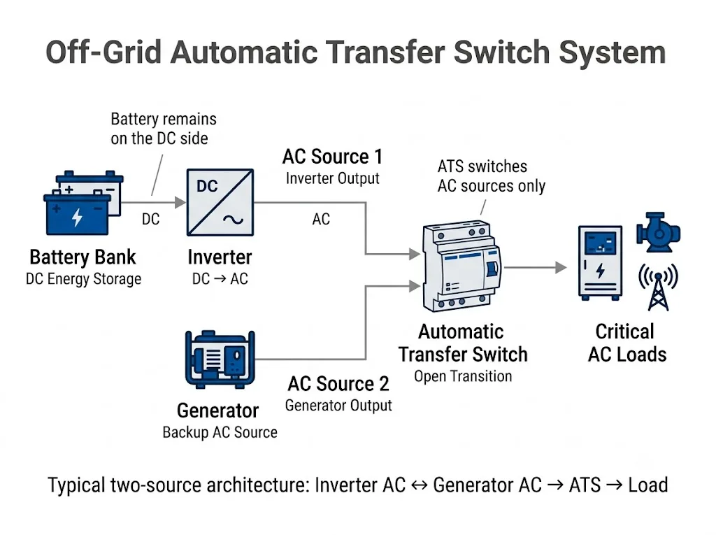
Where Does the ATS Sit in an Off-Grid Power System?
Separating the DC energy path from the AC transfer path prevents one of the most common specification mistakes.
Focus on the ATS relationship column: it shows which equipment actually forms part of the AC transfer function.
| System Component | Funzione principale | ATS Relationship |
|---|---|---|
| Battery / BMS | Stores and manages DC energy | Normally outside the ATS power path |
| Charge controller | Controls DC charging | Does not replace the ATS |
| Inverter / PCS | Converts DC power to AC | Its AC output may be one ATS source |
| Generatore | Provides alternate AC power | Its AC output may be the second ATS source |
| ATS | Transfers the load between sources | Operates at the defined AC transfer point |
Procurement conclusion: battery voltage, Ah or kWh alone cannot determine the ATS rating. Select the ATS from the AC circuit it actually switches.
Which Two AC Sources Need to Be Switched?
IEC 60947-6-1:2026 addresses transfer switching equipment used to transfer a load between power-supply sources. For the compact two-source ATS application discussed here, the practical starting point is therefore simple: identify Source 1 and Source 2 before selecting the switch. [1]
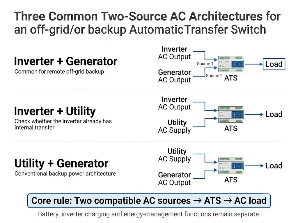
Inverter + Generator
This arrangement is relevant to remote sites where an inverter normally supports the load and a generator provides an alternate AC source when longer backup operation is required.
Victron's transfer-switch documentation provides an example of this principle: two AC inputs can be used for combinations such as inverter plus generator, with one output supplying the downstream load. [2]
Inverter + Utility
An inverter output and utility supply can also form the two AC sources. However, an external ATS is not automatically required just because both sources exist.
Some inverter/chargers include internal AC transfer functionality. Victron, for example, documents MultiPlus-II systems with internal transfer switching as well as a specific external-transfer-switch architecture. [3]
Utility + Generator
Where utility power is available, the ATS can be used in a conventional normal-source and generator-backup arrangement.
The switching concept may be straightforward, but generator starting remains a separate control question. The project must define which controller starts the generator and how the system confirms that the alternate source is ready before transfer.
Does the ATS Start the Generator?
Not every ATS uses the same generator-start method. A generator normally needs a valid start command and enough time to establish acceptable output before the load is transferred.
Some ATSE systems provide dry-contact generator-start outputs. Schneider Electric's TransferPacT documentation, for example, describes genset control using NO and NC dry contacts in applicable configurations. [4]
In other systems, the inverter itself may control generator start. Solis documents a model-specific off-grid architecture in which a hybrid inverter uses a two-wire dry-contact connection to start and stop a compatible generator according to configured system conditions. [5]
Confirm these generator-control details before ordering
- Whether the generator supports remote automatic start.
- Whether the start input is dry contact, two-wire start or another interface.
- Whether the ATS, inverter or another controller sends the start command.
- How source readiness is detected.
- Required start, transfer, retransfer and cool-down delays.
Does the Inverter Already Have a Transfer Function?
This question should be answered before an external ATS is specified.
Victron's MultiPlus-II external-transfer documentation explains that an external transfer switch can replace the internal AC transfer switch in supported configurations. This is a useful example of why transfer functionality may already exist inside inverter/charger equipment. [3]
| Inverter Situation | External ATS Decision | Next Action |
|---|---|---|
| Required transfer already handled internally | May not be needed | Follow the inverter manufacturer's approved architecture |
| Separate external transfer point required | May be suitable | Review source sensing and control logic |
| Independent critical-load circuit | May be suitable | Review the project single-line diagram |
| Complex multi-source system | Standard ATS alone is not enough | Use a system-level engineering design |
Procurement conclusion: send the inverter model and single-line diagram before fixing the external ATS configuration.
Why Open Transition Matters
LEEYEE's standard compact ATS application is based on ordinary open-transition switching.
Open transition means break before make: the existing source is disconnected before the alternate source is connected. Eaton and Schneider Electric describe open-transition ATS operation using this break-before-make principle. [6][7]
This avoids intentional paralleling of the two sources during a normal transfer, but the load experiences an interruption while the transfer occurs. [6][7]
| Tipo di carico | Cosa confermare | Perché è importante |
|---|---|---|
| Pump / motor | Starting and restart behaviour | Restart current can affect source and switch selection |
| Compressor | Permitted restart delay | Immediate restart may not be acceptable |
| PLC / control circuit | Hold-up time | A transfer interruption may reset controls |
| Telecom / IT load | Required continuity | UPS or inverter ride-through may still be necessary |
Come va scelta la corrente nominale dell'ATS?
Start with the maximum design current of the AC load that actually passes through the ATS. Do not size the ATS directly from battery capacity.
Single-phase initial current estimate
Three-phase initial current estimate
These equations provide only an initial load-current estimate. Final selection must also consider the load type, applicable utilisation category, starting or inrush current, upstream protection, conductor rating, fault conditions and the manufacturer's declared ATS ratings.
2P or 4P for an Off-Grid ATS?
Pole selection depends on the actual source and neutral arrangement, not only on whether the system is described as single-phase or three-phase.
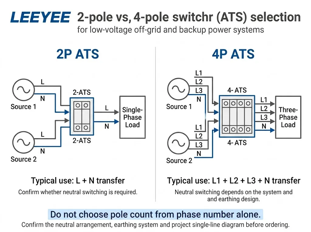
| Circuito tipico | Common Configuration | Da confermare |
|---|---|---|
| Single-phase L + N | 2P may be used | Whether neutral must be switched |
| Three-phase L1 + L2 + L3 + N | 4P may be used | Configurazione di neutralità e messa a terra |
Procurement conclusion: provide the source configuration, neutral arrangement and earthing information before fixing 2P or 4P.
What LEEYEE Product Fits This Application?
The product shown below is the actual compact LEEYEE ATS form relevant to this page. The image shows ATS-2P63 and ATS-4P63 versions with A and B source terminals, Auto / Manual control, status indication and a load output marked “CARGA.”
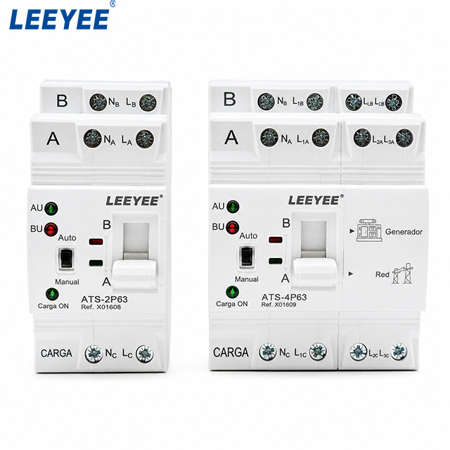
What can be confirmed from the product: the product is a compact integrated two-source ATS. Both versions visibly use A and B source identification and provide Auto / Manual operation. The photographed 4P version also carries Generator and Grid application markings.
What the photo does not prove by itself: the exact rated voltage, utilisation category, transfer time, generator-start output, short-circuit coordination or suitability for a specific inverter architecture. These points must be confirmed from the applicable product datasheet and project documents.
This product format is well matched to the scope of this guide: ordinary low-voltage AC transfer between two defined power sources in compact distribution and backup-power applications.
It should not be presented as a large cabinet-type ATS, bypass-isolation system, closed-transition system or complete microgrid controller.
Where Is This Compact ATS a Practical Fit?
The strongest applications are engineered backup systems where two clearly defined AC sources feed one defined load group.
| B2B Application | Possible Source Pair | Main Selection Check |
|---|---|---|
| Remote telecom cabinet | Inverter + generator | Control continuity and generator logic |
| Farm or irrigation panel | Inverter/utility + generator | Pump starting current and restart sequence |
| Remote monitoring station | Inverter + backup AC source | Control-equipment ride-through |
| Commercial backup cabinet | Utility + generator | Load current, poles and source control |
| Solar EPC auxiliary panel | Inverter output + alternate AC source | Existing inverter transfer functionality |
Procurement conclusion: the application name matters less than the actual two-source AC architecture and transferred load.
When Is a Standard Compact ATS Not Enough?
A standard two-source open-transition ATS should not be stretched into functions that belong to a larger power-management system.
Additional engineering is required when the project needs:
- more than two independently managed power sources;
- intentional source paralleling;
- closed-transition transfer;
- multi-level load shedding;
- complex battery dispatch or microgrid power-flow control;
- zero-interruption transfer for critical equipment.
A Practical ATS Selection Process for B2B Projects
Cosa bisogna inviare prima di effettuare l'ordine?
Off-Grid ATS Project Checklist
- Single-line diagram: show the inverter, generator, utility connection and transferred load.
- Source 1 and Source 2: identify the two AC supplies connected to the ATS.
- Tensione e frequenza di sistema: provide the real project values.
- Phase arrangement: confirm single-phase or three-phase.
- Neutral arrangement: state whether the project requires neutral switching.
- Maximum transferred current: include significant motor, pump or compressor loads.
- Inverter manufacturer and model: provide the manual or relevant wiring page if possible.
- Generator controller: specify the required remote-start interface.
- Permitted transfer interruption: identify loads requiring ride-through or UPS support.
- Protection information: provide upstream protective-device and fault-current information where required.
- Requisiti OEM: provide quantity, label, packaging and documentation requirements.
Need to Confirm the ATS Switching Point?
Send LEEYEE your single-line diagram, inverter model, generator control method, system voltage, phase arrangement, neutral requirement and maximum load current.
We can help confirm whether the intended switching point is suitable for a standard compact open-transition ATS and which project details still require verification.
Domande frequenti
Can an ATS switch between an inverter and a generator?
Yes. An inverter AC output and generator AC output can form the two sources of a suitable transfer-switch architecture. However, the inverter documentation must first be checked because some inverter/chargers already contain transfer functionality or require a specific external-switch arrangement. [2][3]
Can the battery connect directly to the ATS?
Not in the ordinary AC architecture discussed on this page. The battery normally remains on the DC side of the inverter or PCS, while the ATS transfers compatible AC sources on the AC side.
Do I need an external ATS if my inverter already has transfer switching?
Not necessarily. Follow the inverter manufacturer's approved architecture. An additional ATS should only be introduced when the project requires a separate transfer point and the control and wiring arrangement supports it. [3]
Can the ATS automatically start the generator?
It depends on the exact ATS and controller configuration. A Generator marking on the front panel does not by itself prove that the product provides a dedicated generator-start dry contact. Confirm the terminal definition and generator controller interface before ordering or wiring. [4][5]
Un sistema ATS a transizione aperta garantisce un'alimentazione elettrica ininterrotta?
No. Open transition uses break-before-make operation, so the first source is disconnected before the second source is connected. Loads requiring uninterrupted supply may need UPS or inverter ride-through capability. [6][7]
What size ATS do I need for a 10 kW inverter?
Inverter power alone is not enough to select the ATS. Convert the actual AC load into current using the project voltage, phase arrangement and power factor, then check load characteristics, inrush and the manufacturer's declared switch ratings.
Should an off-grid system use a 2P or 4P ATS?
It depends on the phase, neutral and earthing arrangement. LEEYEE's photographed product family includes ATS-2P63 and ATS-4P63 versions, but the final pole configuration must still follow the actual project wiring and neutral-switching requirement.
Can one compact ATS control grid, generator, inverter and battery as four sources?
No. The compact product discussed here should be treated as a two-source AC transfer device, not as a complete multi-source microgrid controller.
Riferimenti
- IEC. IEC 60947-6-1:2026 — Low-voltage switchgear and controlgear — Part 6-1: Multiple function equipment — Transfer switching equipment. Pagina delle pubblicazioni ufficiali dell’IEC.
- Victron Energy. VE Transfer Switch — Introduction. Victron official documentation.
- Victron Energy. MultiPlus-II External Transfer Switch Application — Functionality. Victron official application documentation.
- Schneider Electric. TransferPacT Active Automatic and Automatic User Guide — Genset Start and Alarm. Documentazione ufficiale di Schneider Electric.
- Solis North America. Integrating a Generator with Solis HV Hybrid. Solis official technical guidance.
- Eaton. Automatic Transfer Switches Fundamentals. Eaton official technical guidance.
- Schneider Electric. What Are the Different ASCO ATS Transition Modes? Schneider Electric official FAQ.
