
A diferença entre um SPD 1P+N e um SPD 2P não pode sempre ser determinada a partir do nome do produto. Para um pedido correto de quadro de distribuição monofásico, os compradores devem verificar a real topologia de proteção, sistema de aterramento, modos de proteção, combinação de base e cartucho, escopo de rótulo e certificado.
Índice
Resposta Rápida: SPD 1P+N ou SPD 2P?
Um SPD 1P+N e um SPD 2P nem sempre são eletricamente diferentes. Os nomes podem descrever o formato do produto, enquanto o circuito real pode ser 1+1/CT2 ou 2+0/CT1. Para quadros TT ou TN-S, verifique o diagrama do circuito, os modos de proteção e o escopo do sistema de aterramento aprovado antes de fazer o pedido.
Um SPD verificado 1+1/CT2 é uma direção comum de compra para muitos quadros TT de 230/240 V monofásicos e para projetos TN-S que requerem proteção L–N mais N–PE. Um produto verificado 2+0/CT1 também pode ser adequado quando o projeto exige especificamente caminhos de proteção separados L–PE e N–PE.
Os termos 1P+N e 2P também são usados para MCBs, RCBOs, RCDs e isoladores. A terminologia do SPD relaciona-se a caminhos de proteção contra surtos e construção do produto, não a proteção contra sobrecorrente ou lógica de comutação de disjuntores.
1P+N ou 2P pode descrever polos, módulos ou o formato comercial mostrado no catálogo.
1+1/CT2 ou 2+0/CT1 identifica os caminhos reais de proteção contra surtos.
O diagrama do circuito, o sistema de aterramento e os modos de proteção nominal devem estar em concordância.
O que é um SPD 1P+N?
Um SPD 1P+N é um dispositivo de proteção contra surtos de fase única destinado a sistemas contendo um condutor de fase, neutro e terra de proteção. A descrição normalmente indica que o produto é projetado em torno dos condutores de fase e neutro, em vez de duas fases não relacionadas.
Muitos produtos vendidos como 1P+N utilizam um circuito 1+1 ou CT2: um caminho de proteção entre L e N e outro entre N e PE. No entanto, a redação “1P+N” por si só não prova a disposição dos componentes internos. Os compradores ainda devem verificar o diagrama de circuito do fabricante.
O que é um SPD 2P?
Um SPD 2P geralmente significa um dispositivo de proteção contra surtos de dois polos, dois módulos ou duas posições. Alguns produtos 2P utilizam caminhos de proteção L–PE e N–PE separados, comumente descritos como 2+0 ou CT1.
Outros produtos que apresentam “2P” no nome do modelo utilizam um circuito 1+1 em vez disso. Portanto, 2P não significa automaticamente 2+0. Também não significa “Tipo 2”; a contagem de polos e a classificação do teste de SPD são especificações diferentes.
Separe o Nome do Produto da Topologia de Proteção
A terminologia do catálogo varia entre os fabricantes. Dois produtos podem ocupar ambos dois módulos DIN e parecer semelhantes, enquanto utilizam circuitos internos diferentes. Por outro lado, produtos chamados 1P+N e 2P podem usar o mesmo conceito de proteção 1+1.
| Termo | O que normalmente descreve | O que isso não prova | Verificação necessária pelo comprador |
|---|---|---|---|
| SPD 1P+N | Um produto de formato monofásico fase-plus-neutro | O exato circuito de proteção interna | Solicitar o diagrama de circuito básico |
| SPD 2P | Dois polos, módulos ou posições de produto | Que o produto é necessariamente 2+0 | Confirmar cada modo de proteção declarado |
| 1+1 / CT2 | Proteção L–N seguida de proteção N–PE | As classificações de Tipo, Uc, Up ou corrente de descarga | Verificar classificações para ambos os caminhos de proteção |
| 2+0 / CT1 | L e N protegidos independentemente em relação ao PE | Adequação para cada instalação TT ou TN | Verificar a aprovação do sistema e da posição de instalação |
| DUP tipo 2 | Uma classificação de teste SPD | O número de polos ou topologia interna | Manter a classificação de Tipo separada do 2P |
Peça ao fornecedor para informar se a montagem completa é 1+1/CT2 ou 2+0/CT1 e para identificar os modos de proteção L–N, L–PE e N–PE.
SPD 1+1 vs SPD 2+0: Caminhos de Proteção Internos
A topologia interna determina como a corrente de surto é desviada. É mais importante para a seleção de engenharia do que o número de módulos visíveis na parte frontal do produto.
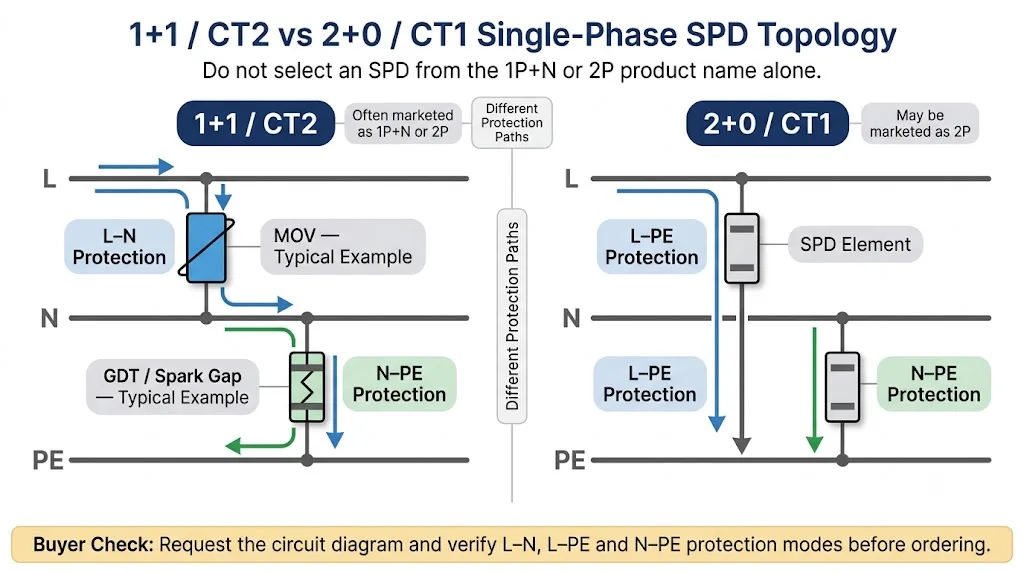
Proteção 1+1 / CT2
Um design típico de 1+1 contém um elemento limitador de tensão entre L e N e um elemento de comutação, como um GDT ou gap de centelha, entre N e PE. As tecnologias exatas dos componentes devem ser confirmadas para o modelo selecionado.
Proteção 2+0 / CT1
Um design típico de 2+0 fornece caminhos de surto separados de L para PE e de N para PE. A tecnologia do componente, a corrente de fuga e o comportamento TOV dependem do design real e não podem ser inferidos pela expressão “2P”.
Exemplo Publicado: Por que “2P” nem sempre significa 2+0
Um SPD monofásico oficialmente publicado possui “2P” em sua designação de produto, enquanto o fabricante descreve seu arranjo elétrico como uma configuração 1+1 para sistemas TT e TN.
Este exemplo demonstra por que os compradores devem verificar o diagrama oficial do circuito e os modos de proteção em vez de interpretar “2P” como uma comprovação automática de uma topologia 2+0.
Veja a referência do fabricante de terceiros
As informações sobre produtos de terceiros são citadas apenas para ilustrar a variação na terminologia da indústria. A LEEYEE não é afiliada, patrocinada ou endossada pelo fabricante mencionado.
Comparação de Compradores: SPD 1P+N vs SPD 2P
| Ponto de comparação | Produto chamado 1P+N | Produto chamado 2P | Ação de compra correta |
|---|---|---|---|
| Nomeação de produto | Usualmente fase mais neutro | Usualmente dois polos ou dois módulos | Não aprove aprovação apenas pela nomenclatura |
| Topologia possível | Freqüentemente 1+1/CT2 | Pode ser 1+1/CT2 ou 2+0/CT1 | Solicitar o diagrama de circuito |
| Caminhos de proteção | Frequentemente L–N e N–PE | Pode ser L–PE e N–PE ou L–N e N–PE | Verifique os modos de proteção individualmente |
| Aplicação TT | Comumente selecionado quando verificado como CT2 | Depende da topologia e da posição do RCD | Estado da TT e posição do RCD na RFQ |
| Aplicação TN-S | Adequado onde o projeto aprovado requer L–N mais N–PE | As versões CT1 e CT2 podem co-existir | Siga a exigência do modo de proteção do projeto |
| Componente N–PE | Frequentemente um GDT ou gap de faísca em produtos 1+1 | Depende do circuito real | Confirme a tecnologia e a classificação do modo |
| Cartuchos | Os módulos de fase e N–PE podem ser diferentes | Os módulos podem ser idênticos ou diferentes | Verifique os códigos dos módulos sobressalentes individuais |
| Uc e Up | Podem ser especificados para L–N e N–PE | Podem ser especificados para L–PE e N–PE | Compare os valores por modo de proteção |
| Escopo do certificado | Deve cobrir a combinação completa de base e cartucho | Deve cobrir o conjunto completo exato | Combinar o certificado, rótulo e lista de materiais (BOM) |
| Principal risco | Assumindo que cada produto 1P+N tem o mesmo circuito | Assumindo que cada produto 2P é 2+0 | Aprovar a topologia antes da produção em massa |
Por que a Topologia de Proteção é Importante
Proteção L–N
A maioria das cargas monofásicas opera entre L e N. Um modo de proteção L–N direto pode, portanto, ser importante ao avaliar o nível de proteção de tensão visto pelo equipamento a jusante.
Proteção L–PE e N–PE
Pulsos de modo comum também devem ser desviados para o sistema de aterramento equipotencial. O nível de proteção completo depende do circuito e do comprimento e roteamento dos condutores da instalação.
Coordenação de RCD
Em sistemas TT, a posição do SPD em relação ao dispositivo de corrente residual afeta o arranjo de conexão aceitável e deve ser incluída nas informações de seleção.
Controle de substituição
O módulo do lado L e o módulo N–PE podem usar tecnologias e classificações diferentes. A substituição incorreta pode criar um risco de desempenho, serviço e garantia.
Qual SPD Você Deve Escolher para TT ou TN-S?
Sistema TT Monofásico
Para muitas placas TT de 230/240 V, especialmente onde o SPD está instalado a montante do RCD principal, um verificado SPD 1+1/CT2 é uma direção comum de compra.
- Confirmar os modos de proteção L–N e N–PE.
- Confirmar o elemento de comutação N–PE e suas classificações.
- Declarar se o SPD está a montante ou a jusante do RCD.
- Verifique o comportamento TOV e as instruções de aplicação do fabricante.
- Siga as regras nacionais de instalação aplicáveis.
Sistema TN-S Monofásico
Projetos TN-S podem usar produtos CT1 ou CT2 dependendo dos caminhos de proteção exigidos, do design da instalação e da aplicação aprovada pelo fabricante.
- Use 1+1/CT2 onde é necessária proteção L–N mais N–PE.
- Use 2+0/CT1 onde a proteção L–PE mais N–PE é especificada.
- Não assuma que uma topologia é universal para todos os painéis TN-S.
- Compare os dados Uc, Up e TOV para os modos de proteção reais.
- Ajuste a escolha final à especificação do projeto.
Determinar se o SPD está instalado antes ou após a separação do PEN. Após a separação, N e PE são condutores separados. Antes da separação, uma descrição genérica de 1P+N ou 2P não é suficiente para aprovar a configuração.
Fluxo de Seleção de SPD Monofásico TT vs TN-S
Utilize o sistema de aterramento, a posição do RCD ou do PEN e a topologia de proteção real como entradas de decisão. Não comece com o número de módulos mostrados em um catálogo de fornecedor.
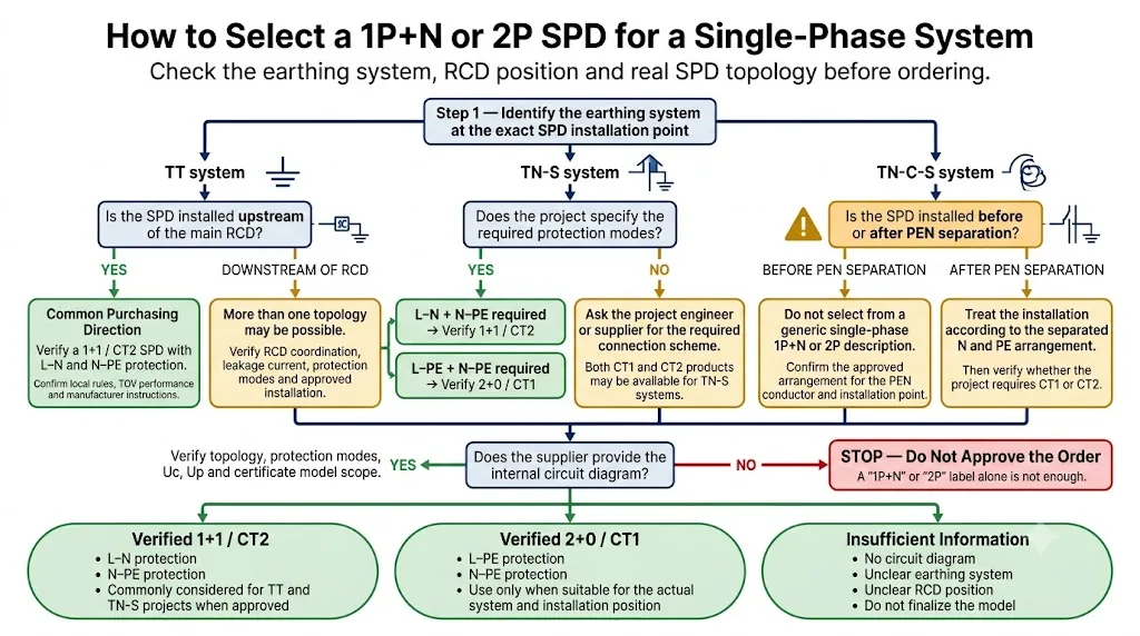
- Identificar o sistema de aterramento na localização do SPD. Confirmar TT, TN-S, TN-C-S ou outra configuração no ponto de instalação exato.
- Confirmar a posição do RCD ou do PEN. Declarar se o SPD está a montante ou a jusante do RCD e antes ou depois da separação do PEN, quando aplicável.
- Verificar a topologia real e os modos de proteção. Confirmar 1+1/CT2 ou 2+0/CT1 e identificar os caminhos L–N, L–PE e N–PE.
- Compare as classificações e os documentos de pedido. Verificar Uc, Up, classificações de descarga, base, cartuchos, rótulo, ficha técnica e escopo do modelo de certificado.
Um rótulo de produto que mostra apenas 1P+N ou 2P não é evidência suficiente da topologia interna ou da adequação do sistema.
Qual Versão é Melhor para Estoque de Distribuidor?
O melhor SKU em estoque não é simplesmente o produto rotulado como 1P+N ou 2P. É o produto com a faixa de aplicação verificada mais ampla, módulos de substituição controlados e documentação que corresponda aos mercados-alvo.
Perfil de Estoque Recomendado para Muitos Mercados IEC
- Aplicação de 230/240 V claramente declarada Tensão nominal, frequência e escopo do sistema estão documentados.
- Circuito 1+1/CT2 verificado, quando apropriado Caminhos de proteção L–N e N–PE são mostrados na ficha técnica.
- Escopo TT e TN-S declarado por escrito Não confie apenas em uma declaração de venda verbal.
- Construção plugável Suporta vendas de módulos de substituição e manutenção em campo mais fácil.
- Códigos de módulo separados Os cartuchos L-side e N–PE podem ser identificados sem confusão.
- Dados Uc e Up específicos do modo Os compradores podem comparar os caminhos protegidos reais.
- Proteção de backup declarada Condições máximas permitidas de fusível ou disjuntor estão disponíveis.
- Pacote de certificado completo A combinação de base e cartucho encomendada está incluída no escopo.
Compare as condições da rede local, a terminologia do cliente, os sistemas de aterramento, os requisitos de TOV e as expectativas de certificação em cada mercado-alvo.
O que a LEEYEE Confirma Antes da Cotação
Antes de recomendar um SPD monofásico para um OEM, distribuidor ou construção de painel pedido, as informações da aplicação devem ser convertidas em uma especificação de produto controlada.
Lista de Verificação para OEM e Pedido em Grande Escala
Um pedido em grande quantidade não deve avançar para a aprovação da etiqueta ou produção em massa até que o sistema, a topologia, os módulos e a documentação tenham sido verificados em relação ao mesmo modelo completo.
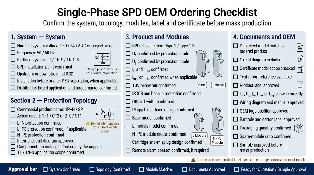
- Sistema e ponto de instalação Confirmar tensão, frequência, sistema de aterramento, posição do RCD e ponto de separação do PEN.
- Esquema de conexão Especifique 1+1/CT2 ou 2+0/CT1 em vez de apenas 1P+N ou 2P.
- Modos de proteção Identifique todos os caminhos de proteção necessários L–N, L–PE e N–PE.
- Classificação do SPD e capacidades de descarga Confirme o tipo, In, Imax, Iimp e Itotal, quando aplicável.
- Uc, Up e TOV Verifique os valores para os modos reais de proteção, não um único valor principal.
- Proteção contra curto-circuito e de backup Confirme o ISCCR e a proteção a montante máxima permitida.
- Combinação de base e cartucho Registre os códigos exatos da base, do módulo L e do módulo N–PE.
- Etiqueta e contato remoto Aprove o modelo, as classificações, a indicação de status e a lógica NO/NC/COM, se necessário.
- Certificado e documentos técnicos Faça corresponder o conjunto encomendado à ficha técnica, ao relatório e ao escopo do certificado.
- Amostra OEM e aprovação da embalagem Aprove o logotipo, o manual, o código de barras, as caixas e a proporção de módulos de reserva antes da produção.
A IEC 61643-11:2025 contém os requisitos específicos para CA de DPS de baixa tensão e é usada em conjunto com os requisitos comuns da IEC 61643-01:2024. Os compradores devem confirmar a edição da norma aceita e as regras de transição para o mercado de destino e o esquema de certificação.
Modelo de RFQ para um SPD Monofásico
Use este formato para evitar receber cotações de produtos que pareçam semelhantes, mas usem circuitos ou combinações de módulos diferentes.
Especificação do comprador copiável
Aplicação: quadro de distribuição CA monofásico
Tensão nominal do sistema: ______ V CA
Frequência: 50 / 60 Hz
Sistema de aterramento no local do DPS: TT / TN-S / TN-C-S / Outro
Posição do DPS: a montante / a jusante do DR
Posição do PEN, se aplicável: antes / após a separação
Topologia exigida: 1+1 CT2 / 2+0 CT1
Modos de proteção exigidos: L-N / L-PE / N-PE
Classificação do DPS: Tipo 2 / Tipo 1+2
Uc por modo de proteção: ____________________
Up por modo de proteção: ____________________
In: ______ kA
Imax: ______ kA
Iimp ou Itotal, se aplicável: ______ kA
Requisito de TOV: _________________________
ISCCR: ______ kA
Proteção de retaguarda máxima: _______________
Construção: plugável / fixa
Largura DIN: ______ módulos / ______ mm
Modelo base: ______________________________
Modelo do módulo L: __________________________
Modelo do módulo N-PE: _______________________
Contato remoto: obrigatório / não obrigatório
Certificado ou norma exigidos: _________
Requisitos de etiqueta OEM: __________________
Requisitos de embalagem: __________________
Quantidade do pedido: __________________________
Quatro Erros Comuns de Compra
Um produto com 2P no nome do modelo ainda pode usar um circuito 1+1.
Os caminhos de proteção do DPS não são o mesmo que os polos de comutação ou de sobrecorrente de um MCB.
A seleção TT e TN-C-S não pode ser concluída sem o ponto de instalação.
Um Imax elevado não corrige a topologia, o Uc, o Up, a TOV ou o escopo do certificado incorretos.
Perguntas mais frequentes
Um DPS 1P+N é o mesmo que um DPS 2P?
Não necessariamente. Ambos os produtos podem ocupar dois módulos DIN, e alguns fabricantes usam as descrições para produtos semelhantes. O circuito interno pode ser 1+1/CT2 ou 2+0/CT1, portanto o diagrama do circuito deve ser verificado.
Todo SPD 1P+N usa um circuito 1+1?
Muitos produtos 1P+N usam proteção L–N mais N–PE, mas os compradores não devem assumir isso sem verificar os modos de proteção declarados e o circuito.
2P significa SPD Tipo 2?
Não. 2P normalmente descreve os polos ou o formato do produto. Tipo 2 é uma classificação de ensaio do SPD. Um produto pode ser tanto 2P quanto Tipo 2, mas os dois termos descrevem propriedades diferentes.
Qual SPD é comumente selecionado para um quadro monofásico TT?
Um SPD 1+1/CT2 verificado é uma opção comum para muitos quadros TT, especialmente a montante do DR principal. A seleção final deve seguir o sistema real, o projeto, as normas locais e as instruções do fabricante.
Um quadro TN-S pode usar 1+1 ou 2+0?
Ambas as topologias podem estar disponíveis para aplicações TN-S. A escolha correta depende de o projeto exigir proteção L–N mais N–PE ou proteção separada L–PE e N–PE, juntamente com os dados de produto aprovados.
O que um comprador deve solicitar antes de aprovar o pedido?
Solicite o esquema elétrico oficial, valores de Uc e Up específicos por modo, capacidades de descarga, dados de TOV, códigos de base e cartucho, instruções de proteção de reserva e âmbito do modelo do certificado.
Precisa Confirmar um SPD Monofásico Antes de Fazer o Pedido?
Envie à LEEYEE a tensão do sistema, o sistema de ligação à terra, a posição do RCD ou PEN, a topologia necessária, as classificações, o certificado e a quantidade da encomenda. Podemos ajudar a confirmar a base, os módulos, a etiqueta e a documentação OEM antes da cotação ou aprovação da amostra.
Referências técnicas
- IEC. IEC 61643-11:2025, requisitos e métodos de ensaio para descarregadores de sobretensões (SPD) de baixa tensão ligados a sistemas de energia de baixa tensão em corrente alternada. Página da publicação IEC .
- IEC. IEC 61643-01:2024, requisitos comuns e métodos de ensaio para descarregadores de sobretensões de baixa tensão. Página da publicação IEC .
- Phoenix Contact. Fundamentos da Proteção contra Raios e Sobretensões, incluindo esquemas de ligação CT1, CT2, x+0 e x+1 e a sua aplicação em sistemas TN e TT. Guia técnico .
- Informação de produto de fabricante externo citada como exemplo publicado de um produto que utiliza a designação "2P", sendo descrito como uma configuração monofásica 1+1. Acedido apenas para fins de comparação terminológica. Referência oficial do fabricante .
