
For a three-phase automatic transfer switch, choosing the pole configuration is not only a mechanical decision. The real engineering question is whether the load neutral should remain continuously connected or transfer with the active source. That decision can affect generator neutral bonding, earth-fault protection, RCD operation and the treatment of N, PE and PEN conductors.
Índice
When should an ATS switch the neutral?
A switched-neutral ATS transfers the load neutral between the normal and alternate sources instead of leaving the neutral permanently connected. In a three-phase four-wire system, this is normally implemented using a fully rated fourth pole that switches N together with L1, L2 and L3.[5]
Switched neutral is commonly considered when source-neutral separation is required, including applications where an alternate generator is designed with its own neutral-earth reference or where the neutral arrangement affects ground-fault sensing.[5][7]
Fazer não use a shortcut such as “TT always means 4P” or “TN-S always means 3P.” The final decision depends on the earthing system, generator neutral-to-earth bonding, PEN separation point, RCD/GFP arrangement and applicable project rules.
Pole count is the result of the neutral and earthing design—not the starting point of the decision.The following table gives an initial engineering direction. It does not replace the approved single-line diagram, generator documentation or applicable national wiring rules.
| System condition | Neutral approach | ATS direction | Confirmar antes de realizar o pedido |
|---|---|---|---|
| Common neutral reference | Neutral may remain solid | Solid-neutral arrangement may be suitable | N-E reference and fault-protection design |
| Separately derived generator arrangement | Source neutrals separated | 4P switched neutral commonly considered | Generator bonding and grounding arrangement |
| Sistema TT | Neutral isolation requires close review | Often switched where required by project rules | RCD, isolation rules and generator earthing |
| Sistema TN-S | N and PE are separate | Solid or switched neutral may be appropriate | Source bonding and protection design |
| TN-C / TN-C-S before PEN separation | PEN must remain continuous | Do not switch PEN as a normal neutral | ATS position relative to PEN separation |
| TN-C-S after PEN separation | Downstream N can be evaluated separately | Depends on source and protection design | Generator bond, PE continuity and RCD/GFP scheme |
Procurement conclusion: confirm the source-neutral and earthing arrangement before fixing the ATS pole configuration.
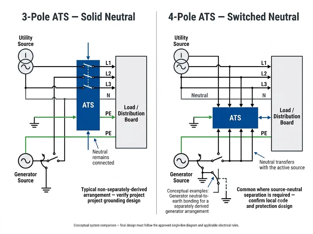
Solid Neutral vs Switched Neutral ATS: What Is the Difference?
In a solid-neutral transfer arrangement, the phase conductors transfer between the two sources while the neutral remains continuously connected. In a 4-pole switched-neutral ATS, the neutral is also transferred through a dedicated, fully rated pole.[5]
This is more than a mechanical difference. The neutral is part of the system reference and earth-fault current path, so the correct configuration depends on how each source is grounded and bonded.
Neutro sólido
The normal-source neutral, alternate-source neutral and load neutral remain electrically connected.
Significado do comprador: commonly evaluated where the alternate source does not establish a separate neutral-earth reference.
Neutro comutado
A dedicated neutral pole transfers the load neutral between the normal and alternate sources.
Significado do comprador: commonly evaluated where source-neutral separation is required.
Overlapping Neutral
The neutral uses a make-before-break sequence so neutral continuity is maintained momentarily during transfer.[6]
Significado do comprador: this is a specialist manufacturer-engineered transfer function, not a normal field modification.
IEC 60947-6-1:2026 is the current IEC edition covering transfer switching equipment, including ATSE. Its published scope states that overlapping-neutral TSE remains outside the types covered by this edition. If a project requires overlapping neutral, verify the manufacturer's declared compliance and test basis with the project approval authority.[1]
How does this apply to the LEEYEE compact ATS?
LEEYEE supplies the compact integrated ATS style shown below, with manual/automatic controls and visible source-status indication on the front panel. The photographed product family includes a 2-pole version for single-phase applications and a 4-pole version for four-conductor transfer applications.
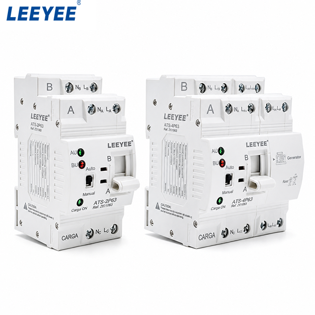
The 4P product is relevant to this topic, but 4P alone does not answer the engineering question
The right-hand LEEYEE unit shown above is the product configuration most directly related to this article because a three-phase four-wire switched-neutral application requires a neutral pole in addition to L1, L2 and L3.
However, the presence of four poles does não mean that the same ATS should automatically be used in every TT, TN-S or TN-C-S project. The project still has to establish whether the neutral should be switched and whether the model's actual switching sequence and electrical characteristics match the approved system design.
Overlapping-neutral operation, bypass isolation and other specialist transfer architectures discussed in engineering literature should not be assumed to be standard functions of this compact LEEYEE ATS. They require separate product and project confirmation.
How do TT, TN-S and TN-C-S systems affect neutral switching?
TT, TN-S and TN-C-S describe different relationships between the source neutral, earth and protective conductors. These relationships change what must be checked before an ATS neutral is left solid or switched.
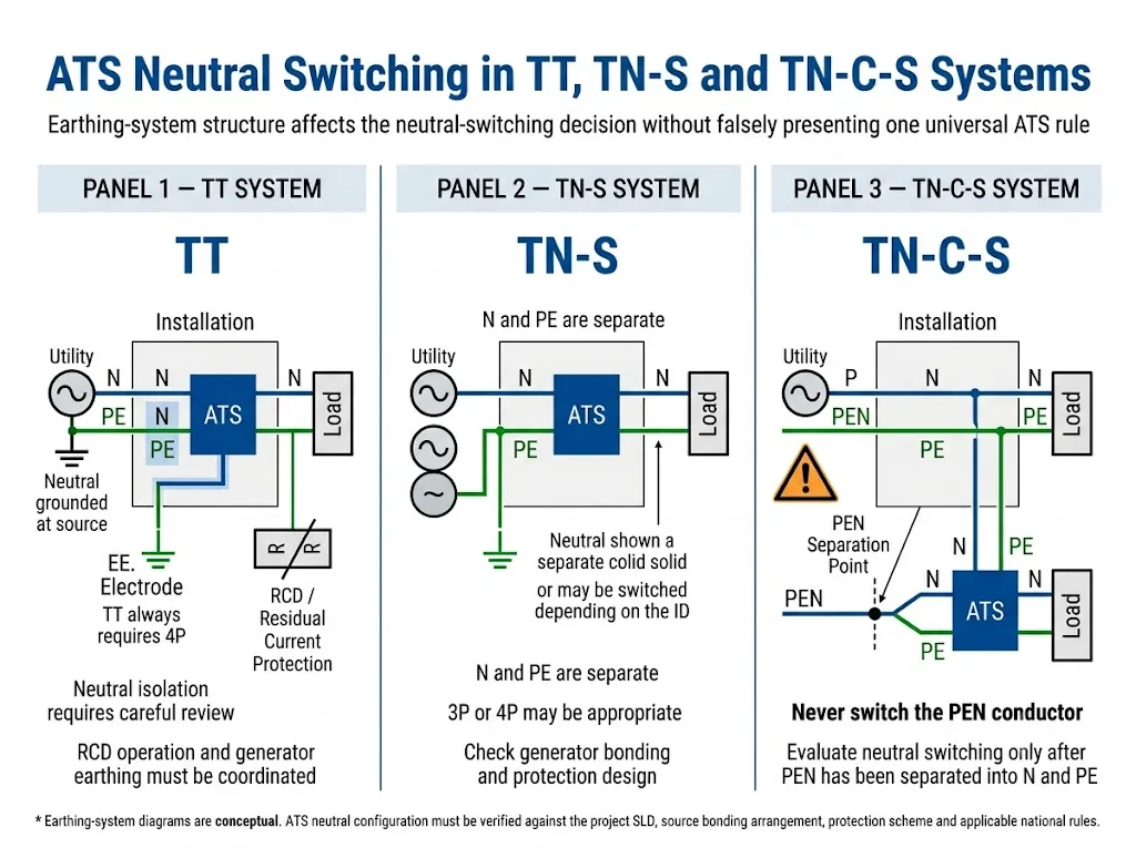
TT systems: why does neutral switching need special attention?
In a TT system, the source neutral is earthed at the source while exposed conductive parts of the installation are normally connected to a local earth electrode. Because the earth-fault loop can have relatively high impedance, residual-current protection is normally central to automatic disconnection for fault protection.[4]
Neutral switching therefore has to be evaluated together with RCD operation and the earthing method used when the generator or alternate source supplies the load.
As one current national example, IET guidance for BS 7671:2018+A4:2026 states that isolation in TT or IT installations requires disconnection of all live conductors. This is a UK requirement and should not be treated as a universal rule for every country, but it demonstrates why neutral isolation can be particularly important in TT projects.[8]
TN-S systems: can the neutral remain solid?
In a TN-S system, N and PE are separate conductors. The neutral can therefore be evaluated independently, while PE must remain continuous and must not be treated as an ATS switching pole.
A TN-S designation does not by itself determine whether the neutral should remain solid or be switched. If the alternate source shares the existing neutral reference, a solid-neutral arrangement may be appropriate. If the generator is designed to establish its own neutral-to-earth reference while supplying the load, a switched-neutral arrangement may be required as part of the complete grounding design.[5][7]
TN-C-S systems: never switch the PEN conductor
A PEN conductor must not be interrupted as though it were an ordinary neutral. In TN-C, the PEN performs both neutral and protective-conductor functions. Schneider Electric's IEC-based Electrical Installation Guide states that the neutral in a TN-C scheme must not be open-circuited because it also constitutes the protective conductor.[3]
In a TN-C-S installation, first identify where PEN is separated into individual N and PE conductors. Only the downstream N conductor should then be evaluated for switching. PE must remain continuous.
This also means ATS location matters. Two projects can both be called TN-C-S but still require different engineering reviews if the transfer switch is installed at a different point relative to PEN separation.
How does generator neutral bonding affect the ATS?
Generator grounding is one of the main reasons not to select the ATS from pole count alone. Whether the alternate source shares the normal-source neutral reference or operates with a separate neutral-earth reference changes the correct transfer arrangement.
Cummins illustrates two common approaches. With a 4-pole switched-neutral transfer switch, the generator neutral can be isolated from the normal-source neutral and may be configured as a separately derived source under the applicable design rules. With a solid-neutral arrangement, the generator neutral remains connected to the service neutral; an additional neutral-ground bond can then create multiple ground-fault current paths.[7]
Do not treat “4P = separately derived” as a universal global rule. The terminology and bonding requirements depend on the applicable electrical code and approved system design. Confirm the generator manufacturer's documentation together with local project requirements.
Solid-neutral generator arrangement
When the alternate-source neutral remains continuously connected to the normal-source neutral, the system has to be reviewed as one neutral network. Any generator-side neutral-to-earth bond must be checked carefully because an additional bonding point can create unintended parallel current paths.[7]
Switched-neutral generator arrangement
When the ATS switches the neutral, the inactive source neutral is isolated from the load neutral. This can support an arrangement in which the active generator provides the required neutral-earth reference. The exact bonding location and grounding conductors must still be confirmed from the project design.[5][7]
How can neutral switching affect RCD and ground-fault protection?
Residual-current and ground-fault protection depend on predictable current paths. If neutral and earth are connected at more than the intended bonding point, part of the current may follow a parallel path and change what the protection device detects.
Cummins links switched neutral with applications requiring accurate ground-fault sensing and explains why an unintended additional N-G bond in a solid-neutral arrangement can create multiple ground-fault paths.[7] In TT installations, RCD operation is particularly important because earth-fault loop impedance is normally too high for ordinary overcurrent protection alone to provide the required automatic disconnection.[4]
If the ATS transfers correctly but an RCD or ground-fault system behaves unexpectedly, check the complete N, PE, bonding and sensing arrangement instead of assuming the transfer mechanism itself is the only problem.
Switched Neutral ATS Decision Flow
A useful ATS selection process starts with the project single-line diagram, not the product catalogue. The following flow shows the questions an electrical contractor, panel builder, generator integrator or engineering buyer should answer before fixing the neutral configuration.
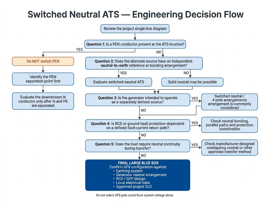
Step 1: Is a PEN conductor present at the ATS location?
If yes, first identify the PEN separation point. A PEN conductor performs a protective function and must not be switched as an ordinary neutral.[3]
Step 2: Does the alternate source have its own neutral-earth reference?
If the generator or alternate source uses a different bonding arrangement, source-neutral separation becomes an important design question. This is a common reason to evaluate a switched-neutral ATS.[5]
Step 3: Is the generator designed as a separately derived source?
If yes, confirm neutral switching together with generator bonding and grounding. Do not select the ATS independently from the source earthing design.[7]
Step 4: How does the protection system detect earth faults?
Review RCDs, ground-fault relays and any sensing arrangement that depends on a defined current-return path. Check for unintended parallel N-PE paths before approving the design.
Step 5: Does the load require neutral continuity during transfer?
Some systems use a manufacturer-designed overlapping-neutral function to maintain neutral continuity during transfer. ASCO describes this as a make-before-break neutral sequence, unlike a conventional switched neutral that is commonly break-before-make.[6]
This is a specialist engineering function and should not be assumed to be part of the standard compact LEEYEE ATS shown on this page. IEC 60947-6-1:2026 also does not include overlapping-neutral TSE within the types covered by its current scope.[1]
Common switched-neutral ATS design mistakes
Choosing 4P only because the system is TT
TT requires careful neutral and RCD review, but the final ATS configuration still depends on project rules and source earthing.
Assuming TN-S automatically means solid neutral
TN-S separates N and PE, but generator bonding and fault-protection design still determine whether N should remain solid or switch.
Switching a PEN conductor
A PEN carries both neutral and protective functions and must not be handled as an ordinary switchable neutral.[3]
Adding a second N-E bond
An extra bond in a solid-neutral arrangement can create unintended parallel neutral-earth current paths.[7]
Ignoring RCD or GFP sensing
Incorrect neutral routing can change the fault-current path seen by residual-current or ground-fault sensing equipment.
Ordering before reviewing the SLD
Neutral configuration is part of the physical ATS and panel design. Late changes can require rewiring or equipment replacement.
What should a buyer confirm before ordering a switched-neutral ATS?
For generator packages, low-voltage panels and OEM projects, provide the system information before requesting a final ATS configuration. This reduces the risk of choosing the correct current rating but the wrong neutral arrangement.
Prepare these project details
| Informação | Por que isso importa |
|---|---|
| Diagrama unifilar | Shows source, N, PE/PEN and bonding locations |
| Utility + generator or utility + utility | Defines the source relationship |
| TT, TN-S or TN-C-S | Establishes the earthing context |
| Ponto de separação PEN | Critical for TN-C-S projects |
| Generator neutral-bonding method | Shows whether source-neutral separation may be required |
| RCD / GFP arrangement | Confirms the intended earth-fault sensing path |
| Single-phase or three-phase four-wire load | Helps determine whether the 2P or 4P compact configuration is relevant |
| Rated voltage and current | Required for basic ATS electrical selection |
| Required neutral transfer function | Confirms whether the standard compact ATS matches the project requirement |
| Required standard and market | Determines the compliance basis that must be verified |
| OEM label / documentation requirement | Allows model, drawings and order documents to be reviewed together |
Need to confirm whether the 2P or 4P LEEYEE ATS fits your system?
Share your single-line diagram, earthing system, generator neutral arrangement, rated voltage/current and RCD or ground-fault information. LEEYEE can use these details to support model and OEM configuration review before the order is finalised.
Perguntas mais frequentes
Does a TT system always require a 4-pole ATS?
No universal rule should be stated that way. TT systems require particular attention to neutral isolation, source earthing and RCD operation. Some national rules require all live conductors to be disconnected for isolation in TT systems, but the final ATS configuration must follow the applicable project and national requirements.[4][8]
Can the neutral be switched in a TN-S system?
Yes. N and PE are separate in TN-S, so the neutral can be evaluated independently. Whether it should be switched depends on the source-neutral relationship, generator bonding and protection design.
Can an ATS switch the PEN conductor in TN-C-S?
A PEN conductor must not be treated as an ordinary switchable neutral because it also performs the protective-conductor function. Identify the PEN separation point first and evaluate downstream N only after N and PE have been separated.[3]
Does a switched-neutral ATS make a generator separately derived?
In code systems that use the term “separately derived system,” switching the neutral can isolate the generator neutral from the normal-source neutral and allow the generator to be configured accordingly. The required neutral-ground bond and grounding arrangement must still follow the applicable code and approved generator design.[7]
Can an incorrect neutral arrangement cause RCD nuisance tripping?
Is the pictured LEEYEE 4P ATS automatically suitable for every TT, TN-S or TN-C-S system?
No. The 4P construction makes it relevant to three-phase four-wire applications where neutral transfer is being considered, but project suitability still depends on the actual neutral-switching function, generator bonding, earthing system, RCD/GFP arrangement and applicable local rules.
Does the standard compact LEEYEE ATS use overlapping neutral?
This should not be assumed. Overlapping neutral is a specialist make-before-break neutral-transfer function. It is discussed here to explain the engineering distinction, but any requirement for overlapping neutral must be confirmed separately against the specific ATS model and project documentation.[6]
What information should I send when requesting a 2P or 4P LEEYEE ATS?
Send the project SLD, rated voltage and current, single-phase or three-phase system details, TT/TN-S/TN-C-S earthing arrangement, generator neutral-bonding method, ATS installation position, RCD/GFP arrangement and destination market. These details allow the pole and neutral strategy to be reviewed before model confirmation.
Referências
- Comissão Eletrotécnica Internacional (IEC), IEC 60947-6-1:2026 — Aparelhagem de baixa tensão – Parte 6-1: Equipamentos multifuncionais – Equipamentos de comutação de transferência, Edition 4.0, published 2 April 2026. Página de publicações oficiais da IEC.
- Comissão Eletrotécnica Internacional (IEC), IEC 60364-5-53:2019+A1:2020+A2:2024 CSV — Low-voltage electrical installations – Part 5-53: Selection and erection of electrical equipment – Devices for protection for safety, isolation, switching, control and monitoring, Edition 4.2. Página de publicações oficiais da IEC.
- Schneider Electric Electrical Installation Guide, Breaking of the neutral conductor. Includes requirements and restrictions concerning neutral and PEN conductor interruption in IEC-based systems. View technical guidance.
- Schneider Electric Electrical Installation Guide, TT system – Principle. Covers TT fault-loop characteristics and the role of residual-current protection. View technical guidance.
- Eaton, Fundamentals of Automatic Transfer Switches (ATS). Includes use of a fully rated fourth pole for switched-neutral three-phase applications and separately derived source considerations. View Eaton technical page.
- Schneider Electric / ASCO, What neutral configurations are available for ASCO Transfer Switches? Defines solid, switched and overlapping-neutral arrangements. View ASCO technical FAQ.
- Cummins, Specifying the Right Transfer Switch. Technical guidance covering solid-neutral and switched-neutral ATS configurations, separately derived generator arrangements, neutral bonding and ground-fault sensing. View Cummins technical paper.
- Institution of Engineering and Technology (IET), Protective, isolation and switching devices explained, Wiring Matters, 2026. Includes current BS 7671:2018+A4:2026 guidance for isolation of live conductors in TT and IT installations. View IET guidance.
