
When a compact automatic transfer switch is used in a generator backup or dual-source system, a project may also ask for utility status, generator status, transfer position or alarms to be sent to a BMS, PLC or other monitoring platform. That does not mean every ATS already includes those interfaces.
Este guia explica what must be confirmed when remote monitoring is required around a compact ATS. It is written for panel builders, generator integrators, BMS contractors, facility engineers and project buyers—not as a consumer remote-control tutorial.
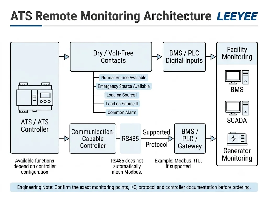
An ATS can only provide remote monitoring when the required outputs or communication functions actually exist in the selected controller or system design. Basic monitoring may use dry or volt-free contacts for source availability, transfer position and alarms. More detailed integration may use a communication-capable controller and an interface such as RS485 with a supported protocol such as Modbus RTU.
For the compact LEEYEE ATS range discussed on this page, dry-contact outputs, RS485, Modbus and BMS communication must not be assumed as standard functions. If a project requires them, the exact model, controller, terminal arrangement and supporting documentation must be confirmed before quotation or model approval.
The compact LEEYEE ATS shown in the current product range is intended first as an automatic source-transfer device, with local Auto / Manual operation and local status indication visible on the product interface. This article explains how a buyer should evaluate additional remote-monitoring requirements around that type of ATS.
The diagrams below are system-integration examples. They are not wiring diagrams for the standard LEEYEE compact ATS and do not state that the product includes dry contacts, RS485, Modbus, Ethernet or a remote BMS interface.
Índice
What Can an ATS Remote Monitoring System Monitor?
The answer depends on the controller. On ATS systems specifically designed for monitoring integration, common data points can include source availability, transfer position, alarms, operating mode, voltage, frequency and event information. Manufacturer implementations show that these functions vary considerably between controller families. [3][4]
The correct engineering approach is therefore to prepare a monitoring-point list first, then verify which of those points can actually be provided by the proposed ATS or surrounding control system.
For procurement, the third column matters most because it shows what must be verified before a model is approved.
| Monitoring Point | O que isso significa | O que deve ser confirmado |
|---|---|---|
| Fonte normal disponível | Source I / utility is considered acceptable. | Whether an external output for this state exists. |
| Fonte de emergência disponível | Source II is available for transfer. | Where this signal comes from and how it is exposed. |
| Carga numa fonte normal | The ATS is supplying the load from Source I. | Whether actual position feedback is externally available. |
| Load on emergency source | The ATS is supplying the load from Source II. | Whether actual position feedback is externally available. |
| Common alarm / fault | The ATS or controller requires attention. | Whether a fault output exists and which conditions it includes. |
| Auto / manual status | Shows the selected operating mode. | Whether this local state is available as an external signal. |
| Transfer failure | A requested transfer did not complete correctly. | Whether the selected controller has this diagnostic. |
| Voltage / frequency | Electrical condition of one or both power sources. | Requires a controller or separate monitoring device that provides these values. |
| Event / alarm history | Supports troubleshooting and maintenance review. | Requires controller memory and documented data access. |
These are possible project requirements, not a list of standard functions on the LEEYEE compact ATS.
Significado do comprador: Do not specify only “ATS with remote monitoring.” Write down the actual status points your BMS, PLC or generator system must receive, then ask the supplier to confirm each point against the exact controller and terminal documentation.
Three Common Ways ATS Status Can Be Sent to a Monitoring System
1. Dry or Volt-Free Contacts
A dry or volt-free contact provides a discrete state rather than a stream of digital data. On a controller designed with external status outputs, individual contacts may represent conditions such as Source I available, Source II available, ATS position or common alarm.
A PLC or BMS digital input can then interpret the contact as open or closed. The contact rating, NO/NC logic, common terminal arrangement and external control circuit must all be checked from the exact wiring documentation.
This method can be practical when the project needs only a small number of simple status points.
2. RS485 With a Supported Protocol
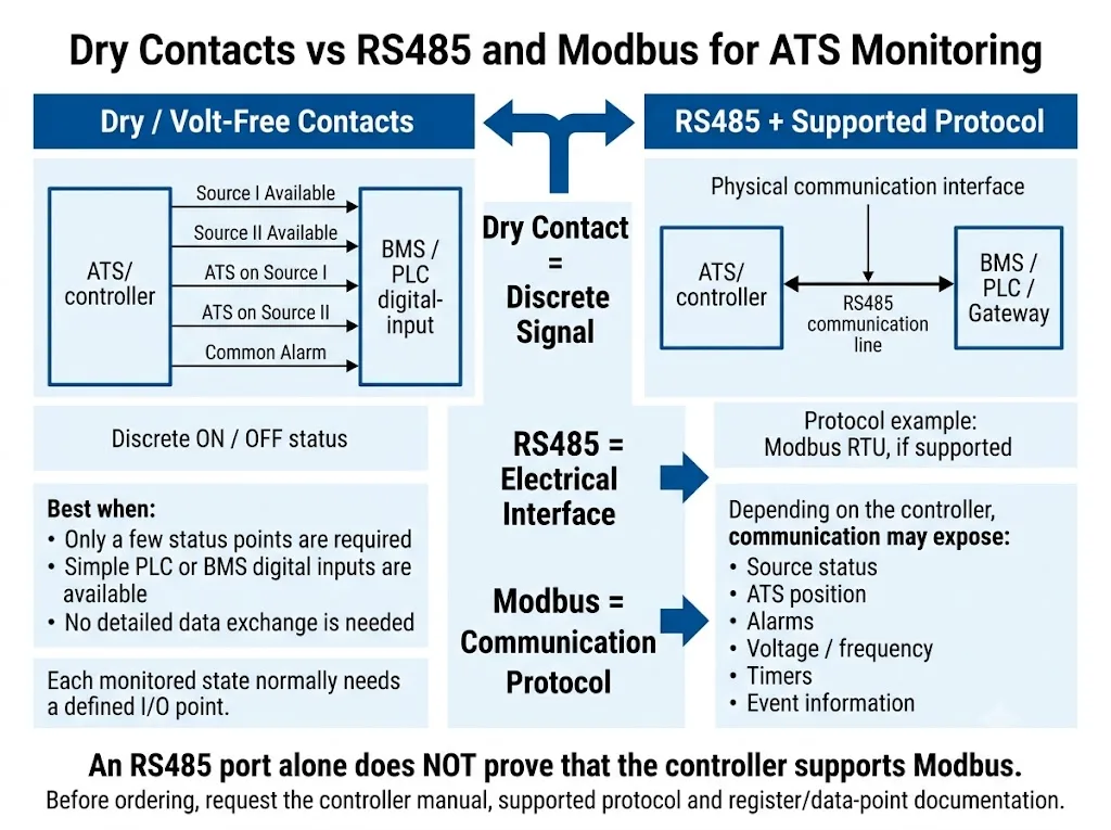
RS485 describes the electrical serial interface. It does not define what the ATS is communicating.
The Modbus Organization publishes the Modbus application protocol separately from the serial-line implementation guidance. Modbus RTU may use RS485, but an RS485 interface does not automatically mean Modbus support. [1][2]
3. Remote Annunciator, Gateway or Supervisory Controller
Some larger or communication-oriented ATS systems use a dedicated remote annunciator, communication module, gateway or supervisory controller. ASCO and Socomec both document examples of this type of manufacturer-specific monitoring architecture. [3][5]
These examples show what is technically possible in ATS systems, but they should not be interpreted as standard functions of the compact LEEYEE ATS.
Dry Contact vs RS485 vs Modbus: What Is the Difference?
| Method | Uso Típico | Main Procurement Check |
|---|---|---|
| Dry / volt-free contact | A small number of discrete ON / OFF states | Whether the required auxiliary outputs actually exist |
| RS485 | Physical serial communication connection | Which protocol, if any, is implemented |
| Modbus RTU | Structured data exchange over a supported serial network | Protocol support, settings and register / data-point map |
| Remote annunciator / gateway | Centralised indication or multi-device monitoring | Compatibility with the exact ATS controller |
Procurement conclusion: select the method from the project requirement and documented controller capability. Do not choose a method only because it sounds more advanced.
Important: an RS485 port alone does not prove Modbus support.
If Modbus is required, ask for the communication manual, supported protocol, communication settings and register or data-point documentation before approving the system.
What Should You Confirm When a Project Specifies Modbus?
The question “Does the ATS have RS485?” is not enough. The BMS or PLC engineer normally needs much more specific information.
- Does the exact controller support Modbus RTU or another required protocol?
- Which physical communication interface is used?
- Is a communication manual available?
- Is a register or data-point map available?
- Which ATS status points can be read?
- Which electrical values, if any, can be read?
- Are alarm or event states available?
- Are any values writable?
- How are device address, baud rate, parity and other settings configured?
- Is an external gateway required?
Eaton's ATC-900 documentation is an example of why this controller-level information matters: Eaton publishes specific Modbus RTU, RS485 and register information for that controller. Socomec likewise documents optional RS485 monitoring on specific ATyS models. These are product-specific examples, not generic ATS capabilities. [3][4]
Generator Start Command Is Not Generator Running Feedback
This distinction is especially important when a compact ATS is used with a standby generator.
A generator-start command tells the generator controls that backup power is required. It does não prove that the generator has started successfully, reached acceptable voltage and frequency, or is ready to carry the load.
If the BMS must display generator-running status, that status may need to come from the generator controller or another documented point in the system design.
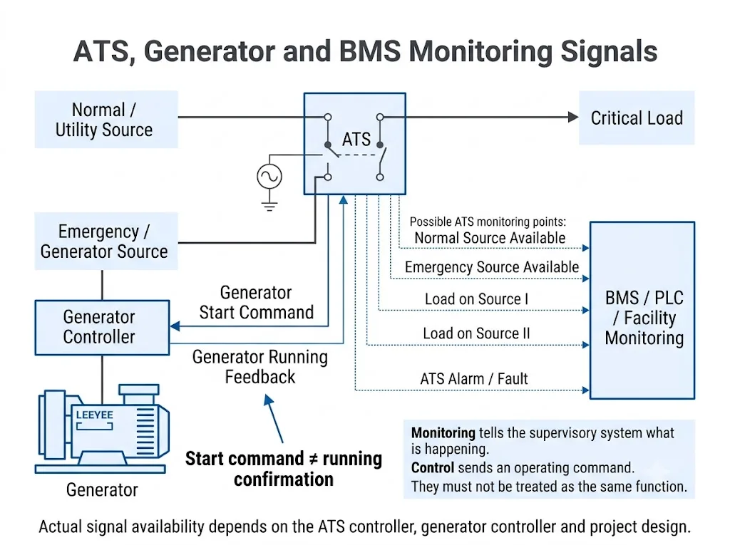
Significado de engenharia: “Generator Start Request,” “Generator Running,” “ATS on Source I” and “ATS on Source II” should be treated as separate project points unless the actual control documentation clearly defines another arrangement.
Remote Monitoring Is Not the Same as Remote Control
Monitoramento remoto means another system can receive or read ATS information. Remote control means an external system can issue an operating command.
An ATS system can provide monitoring without allowing a BMS to initiate transfer. Some manufacturer-specific supervisory systems provide selected test or control functions, but those functions depend on the controller architecture and must be explicitly documented. [5]
Do not infer remote transfer capability from an interface or monitoring function.
Remote transfer, retransfer, generator test or setting changes must be explicitly supported by the exact controller and reviewed against project interlocking, operating permissions and safety requirements.
How Does ATS Monitoring Fit Into a BMS or PLC System?
The automatic transfer function and the supervisory monitoring function should be treated as separate layers.
Discrete-I/O Architecture
ATS / controller → documented auxiliary contacts → BMS or PLC digital inputs.
This is suitable when only a limited number of binary status points is required.
Communication Architecture
Communication-capable controller → supported interface / protocol → PLC, gateway or BMS.
This can be useful when the project requires more status points, measurements or multiple devices.
For the compact LEEYEE ATS: the integration paths above are requirements to verify, not standard functions claimed for the product. If remote monitoring is mandatory, confirm feasibility before finalising the panel design or purchase order.
Typical B2B Project Scenarios
Generator Backup Panel
A panel builder may use a compact ATS primarily for automatic transfer between utility and generator sources. If the project also asks for generator start status, source availability or ATS position to be reported externally, those signals should be checked separately from the main transfer function.
Commercial Building BMS
A building-management specification may request Source I available, Source II available, load position, operating mode and common alarm. The BMS contractor should provide the required point list before the ATS and controller arrangement is finalised.
Industrial or Unattended Site
An unattended facility may require more external status information because operators are not continuously present. If the compact ATS does not provide the required interfaces, the system integrator must determine another documented control or monitoring architecture rather than assuming those functions are built into the ATS.
Does IEC 60947-6-1 Mean an ATS Has BMS or Modbus Functions?
No. IEC 60947-6-1:2026 applies to transfer switching equipment, including automatic transfer switching equipment and stand-alone ATS controllers. Its published scope also notes that auxiliary contacts are outside the scope of this standard. [6]
Therefore, compliance with an ATS product standard does not by itself prove that the product has dry-contact status outputs, RS485, Modbus or a BMS interface.
Significado do comprador: Verify the ATS transfer function and the monitoring / communication requirement separately. A standards statement is not a substitute for checking the actual controller and wiring documentation.
What Should Be Confirmed for a LEEYEE Compact ATS Project?
For the compact 2P / 4P style ATS in the LEEYEE product range, the safest specification method is to separate the standard transfer requirement from any additional monitoring requirement.
| Project Requirement | How to Treat It |
|---|---|
| Automatic transfer between two power sources | Core ATS application; confirm voltage, current and pole configuration. |
| Local Auto / Manual operation | Confirm the exact product operating arrangement. |
| Local source / load indication | Confirm indication functions on the exact model. |
| External source-status contacts | Do not assume; verify terminals and documentation. |
| External ATS-position feedback | Do not assume; verify model-specific auxiliary outputs. |
| RS485 | Do not assume; verify exact controller capability. |
| Modbus RTU | Do not assume; require protocol and data documentation. |
| BMS remote control | Do not assume; requires explicit controller support and project review. |
This distinction keeps the article aligned with the actual compact ATS product instead of presenting high-end communication functions as standard features.
Before Ordering an ATS for a Project With Remote Monitoring
The best time to confirm remote monitoring is before the ATS model and control architecture are frozen.
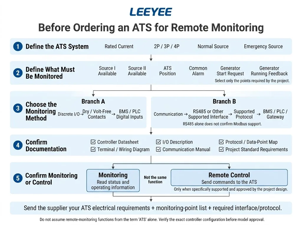
- ATS rated current
- Sistema monofásico ou trifásico
- 2P, 3P or 4P requirement
- Normal-source voltage
- Emergency-source voltage
- Utility / generator or other source arrangement
- Required external source-status signals
- Required ATS-position signals
- Required alarm points
- Generator-start requirement
- Generator-running feedback requirement
- BMS, PLC or SCADA platform
- Dry-contact requirement
- Protocolo de comunicação obrigatório
- Monitoring only or remote control
- Number of ATS units
- Required technical documentation
- Project standard or approval requirement
- Quantidade do pedido
- Requisito de rotulagem ou embalagem OEM
Need to Check Whether a Monitoring Requirement Can Be Supported?
Send LEEYEE your ATS electrical requirements and the BMS or generator monitoring-point list. We can first review the required functions against the applicable product and controller documentation instead of assuming that communication functions are standard.
ATS Remote Monitoring FAQ
Does the compact LEEYEE ATS have Modbus?
This page does not claim Modbus as a standard function of the compact LEEYEE ATS. If Modbus is required for a project, the exact model and controller configuration must be confirmed separately before ordering.
Does the compact LEEYEE ATS have RS485?
RS485 should not be assumed from the product appearance or from the fact that the device is an automatic transfer switch. The exact controller and technical documentation must confirm whether such an interface is available.
Can every automatic transfer switch be monitored remotely?
No. Remote monitoring depends on the controller, auxiliary outputs, communication hardware and system architecture. A standard ATS transfer function does not automatically include remote BMS monitoring.
Is RS485 the same as Modbus?
No. RS485 is an electrical serial interface. Modbus is a communication protocol. Modbus RTU can use RS485, but an RS485 port does not automatically mean that Modbus is supported. [1][2]
Can ATS dry contacts connect to a BMS?
Yes, when the exact ATS or controller provides suitable auxiliary contacts and the BMS input circuit is compatible with the documented contact ratings and wiring logic. The presence of those contacts must be verified first.
What ATS signals are normally useful to a BMS?
Common requirements include source availability, actual ATS position, operating mode and alarms. The project should define which points are truly required instead of assuming every ATS provides all of them.
Does a generator-start output prove that the generator is running?
No. A start request and a running confirmation are different signals. Generator-running feedback normally has to come from a verified point in the generator control system or another documented source.
Can a BMS remotely transfer the LEEYEE compact ATS?
This page does not present remote transfer as a standard function of the compact LEEYEE ATS. Any remote-control requirement must be confirmed against the exact controller and project design before approval.
What should I send LEEYEE if my project needs remote monitoring?
Send the ATS current, system voltage, pole requirement, source arrangement, required status points, BMS or PLC platform, dry-contact requirement, communication protocol requirement and whether the project needs monitoring only or remote control.
Final Engineering Takeaway
The compact LEEYEE ATS and an advanced remote-monitoring system should not be treated as the same thing.
The ATS first solves the source-transfer requirement. If a commercial building, generator system, industrial panel or unattended site also needs BMS monitoring, the external status and communication requirements should be specified separately and checked against the exact product configuration.
The safest procurement sequence is: confirm the ATS electrical configuration → define the monitoring-point list → verify the required outputs or protocol → approve the final system architecture.
Confirm the Monitoring Requirement Before Final Model Approval
Share the electrical configuration and required external monitoring points with LEEYEE. This allows the project requirement to be checked without presenting unverified communication functions as standard ATS features.
Referências
- Modbus Organization. Modbus Specifications and Implementation Guides. Modbus Organization.
- Modbus Organization. MODBUS over Serial Line Specification and Implementation Guide. Official Modbus specifications.
- Socomec. ATyS g Automatic Transfer Switching Equipment. Product documentation describing optional communication and remote-monitoring functions for the specified ATyS family. Socomec ATyS g.
- Eaton. ATC-900 Modbus Communications Guide, IB140006EN. Controller-specific documentation covering Modbus RTU communication and RS485 implementation. Eaton ATC-900 communication guide.
- Schneider Electric / ASCO Power Technologies. ASCO 5310 ATS Remote Annunciator User Guide. Manufacturer documentation for remote indication and selected remote functions on compatible ASCO ATS systems. ASCO 5310 documentation.
- Comissão Eletrotécnica Internacional. IEC 60947-6-1:2026 — Aparelhagem de baixa tensão — Parte 6-1: Equipamentos multifuncionais — Equipamentos de comutação de transferência. IEC 60947-6-1:2026.
