
An automatic transfer switch can be useful at an EV charging station when a load needs to move automatically between two AC power sources.
For the compact LEEYEE ATS shown on this page, the best fit is normally a defined low-voltage AC circuit. That could be an auxiliary panel, control equipment or a selected charging branch.
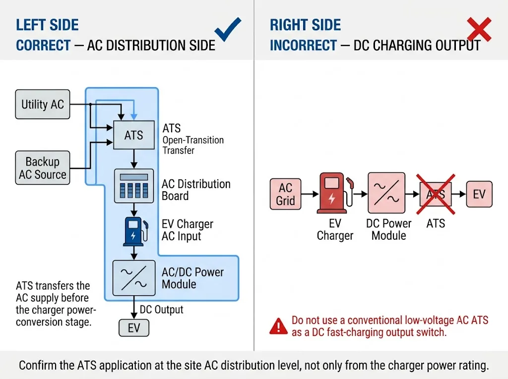
It is não a DC fast-charging output switch. It should not be installed between a charger's DC power module and the vehicle.[1]
Índice
Resposta Rápida
Put the ATS on the AC supply side, before the charger converts power for the vehicle.
Typical source combinations are utility + generator, utility + a suitable PCS AC backup output, or two AC supplies.
Before choosing the ATS, first decide what actually needs backup. Do not size it from the total charging-station kW alone.
| Aplicação | Fit | Significado do Comprador |
|---|---|---|
| Utility ↔ generator for auxiliary loads | Good fit | Typical compact ATS application. |
| Selected EV charger branch | Check first | Confirm real AC current and protection. |
| Utility ↔ PCS backup AC | Verificação do projeto | Confirm PCS and EMS operating logic. |
| Whole high-power charging station | Não assuma | May exceed compact ATS scope. |
| DC charger output ↔ EV | Não | Not the function of this AC ATS. |
Start with the circuit that needs backup, not the total advertised power of the charging station.
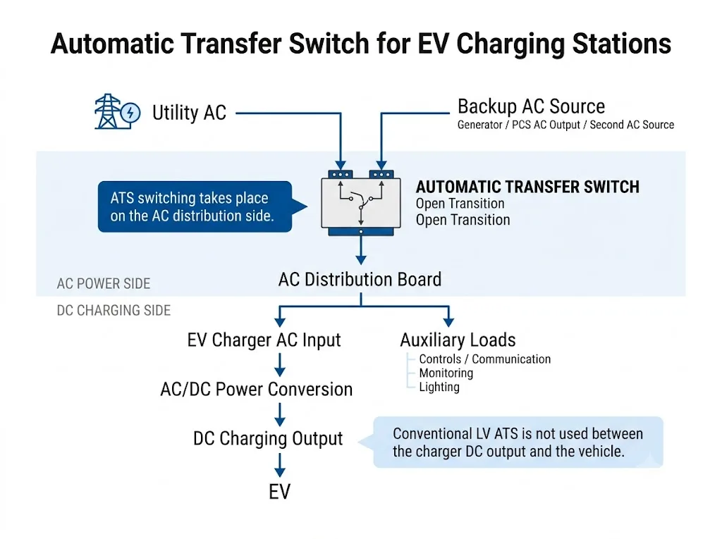
Where Does the ATS Go?
EV charging equipment can contain both AC and DC sections.[1] That is why the first step is to separate the two clearly.
The LEEYEE ATS belongs on the low-voltage AC side. It transfers an AC load between two AC sources.
After that, the EV charger handles its own charging control and power conversion.
Regra simples: ATS before the charger power-conversion stage = possible. ATS between the DC charger output and the EV = not this product's job.
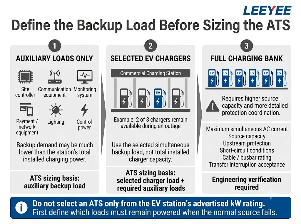
Which Loads Should Be Backed Up?
This decision matters more than the total charger rating.
A charging station may have a large installed capacity but only need a small part of the site to stay powered during an outage.
1. Auxiliary Loads
These may include control systems, communication equipment, network devices, monitoring, payment equipment, lighting and access control.
For a compact ATS, this is often the most practical backup scenario.
2. Selected Chargers
Some projects keep only one or several chargers available during an outage.
In this case, size the ATS from the actual AC current of the selected backup circuit, not from the total installed charger power.
3. Full Charging Bank
Backing up the whole charging station is a different level of project.
It can require much higher current, larger conductors, stronger protection coordination and larger transfer equipment.
Do not assume a compact LEEYEE ATS can serve as the main transfer switch for every high-power charging station. Check the actual circuit and project ratings first.
Generator, BESS or Second AC Source?
Utility + Generator
This is a common ATS arrangement.
When utility power fails, the system can start the generator. Once the backup source is ready, the ATS transfers the selected AC load.
The important point is simple: the generator only needs to supply the loads you decide to keep running.
Utility + BESS / PCS
A BESS can also provide backup power if its PCS provides a suitable AC output.
But this needs more checking than a basic utility-generator system.
Confirm how the PCS works during an outage, how it handles island operation, how neutral and earthing are arranged, and how the EMS controls the system.
For a BESS project, send the single-line diagram and PCS backup-output information. Battery kWh alone is not enough to select the ATS.
Two AC Sources
An ATS can also transfer a load between two compatible AC sources.
Both sources still need to match the project voltage, frequency, protection and ATS requirements.
How Do You Choose Current and Poles?
Do not start from a phrase such as “120 kW charger” or “500 kW station.”
Start from the AC circuit that will actually pass through the ATS.
- Choose the backup load. Auxiliary panel, selected chargers or another defined circuit.
- Confirm the AC system. Voltage, frequency and phase arrangement.
- Find the real maximum current. Use the project load data and charger AC input information.
- Check the backup source. Generator, PCS or second AC supply.
- Check protection. Upstream protection and short-circuit conditions matter.
- Match the LEEYEE model. Confirm current, poles and required control functions.
Current alone is not enough. A calculated load current below the ATS rating does not automatically mean the application is suitable. Protection and short-circuit conditions still need to be checked.
3P or 4P?
| ATS | What It Switches | Main Question |
|---|---|---|
| 3P | L1 / L2 / L3 | Should neutral remain connected? |
| 4P | L1 / L2 / L3 / N | Does neutral also need to transfer? |
Do not choose 3P or 4P from charger power alone.
Check the earthing system, neutral arrangement and the generator or PCS design first.[5]
What Can the LEEYEE Compact ATS Do?
The product shown below is a compact integrated automatic transfer switch for low-voltage AC source transfer.
It is designed around normal open-transition operation. One source is disconnected before the other source is connected.[4]
This means there is a short power interruption during transfer.
The EV charger or control equipment must be able to accept that interruption and restart correctly.
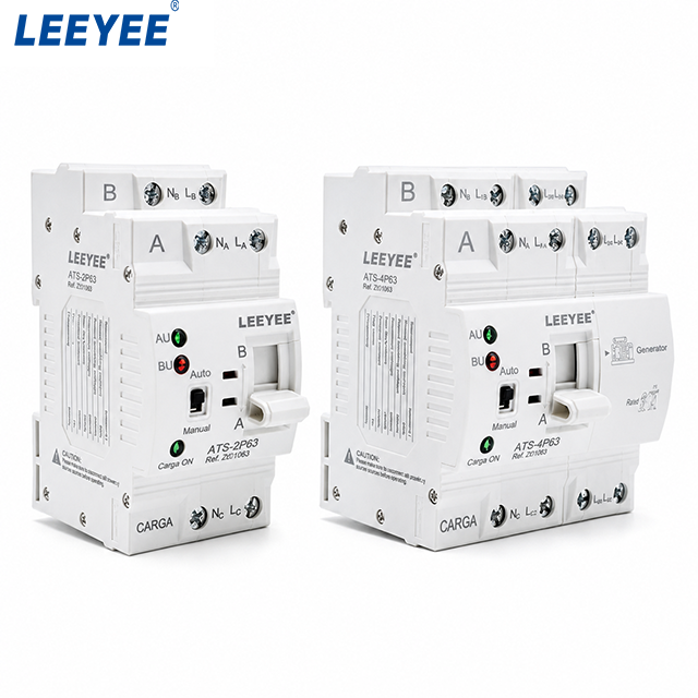
Product boundary: this page is about compact open-transition ATS applications. It is not presenting the product as a closed-transition system, bypass-isolation ATS or large EV charging switchgear.
ATS and EMS Do Different Jobs
| Sistema | Main Job |
|---|---|
| ATS | Transfer the AC load between two sources. |
| EV charger controller | Control the charging equipment and charging process. |
| EMS | Manage power allocation and charging priority. |
| Monitoring / SCADA | Receive operating status and alarms. |
Depending on the selected ATS model, a monitoring system may also receive signals such as:
- Normal Source Available
- Emergency Source Available
- Load to Normal
- Load to Emergency
- Auto / Manual
- Fault Alarm
If these signals are required, confirm the available auxiliary contacts and interface details for the exact LEEYEE model.
What Should You Send Before Ordering?
A useful ATS recommendation needs more than the total charging-station power.
EV Charging ATS Checklist
- Diagrama unifilar
- Normal power source
- Backup power source
- Tensão do sistema
- Frequência do sistema
- Monofásico ou trifásico
- Loads that need backup
- Maximum transferred current
- Charger AC input data
- Requisito de 2P / 3P / 4P
- Sistema de aterramento
- Neutral arrangement
- Upstream protection
- Short-circuit information
- Required status signals
- Acceptable transfer interruption
- Certificados ou documentos necessários
- Quantity and OEM requirement
The single-line diagram is especially useful. It shows the sources, ATS position, downstream loads and protection arrangement in one document.
Need to Check This ATS for Your EV Charging Project?
Send the single-line diagram, voltage, backup source, load current and pole requirement. LEEYEE can help check whether a compact open-transition ATS fits the application.
Perguntas mais frequentes
Is a compact ATS suitable for an EV charging station?
Yes, when it is used on a suitable low-voltage AC circuit within the selected model's ratings. Auxiliary loads and selected charging branches are typical examples.
Can the ATS switch between utility and a generator?
Yes. This is a common ATS application. The generator, load current, poles and protection still need to match the project.
Can the ATS be installed on the DC fast-charging output?
No. The product shown here is for low-voltage AC source transfer, not for switching the charger-to-vehicle DC output.
Can one compact ATS back up the whole charging station?
Only if the complete transferred circuit is within the selected model's verified ratings. Large high-power stations may need a different transfer-switch or switchgear solution.
Should I choose 3P or 4P?
Check whether the neutral needs to switch when the source changes. This depends on the earthing system and the generator or PCS design.
Is open-transition transfer seamless?
No. Open transition disconnects the first source before connecting the second, so the load sees a brief interruption.[4]
Referências
- Comissão Eletrotécnica Internacional (IEC), IEC 61851-1:2017, Electric vehicle conductive charging system – Part 1: General requirements, with Corrigendum 1:2023. Página de publicações oficiais da IEC.
- Comissão Eletrotécnica Internacional (IEC), IEC 60364-7-722:2018, Low-voltage electrical installations – Part 7-722: Requirements for special installations or locations – Supplies for electric vehicles. Página de publicações oficiais da IEC.
- Comissão Eletrotécnica Internacional (IEC), IEC 60947-6-1:2026, Low-voltage switchgear and controlgear – Part 6-1: Multiple function equipment – Transfer switching equipment. Página de publicações oficiais da IEC.
- Eaton, Automatic Transfer Switches (ATS) Fundamentals, technical explanation of open-transition and closed-transition transfer modes. Eaton technical resource.
- Schneider Electric / ASCO Power Technologies, Configurações neutras em comutadores de transferência. Schneider Electric technical resource.
