
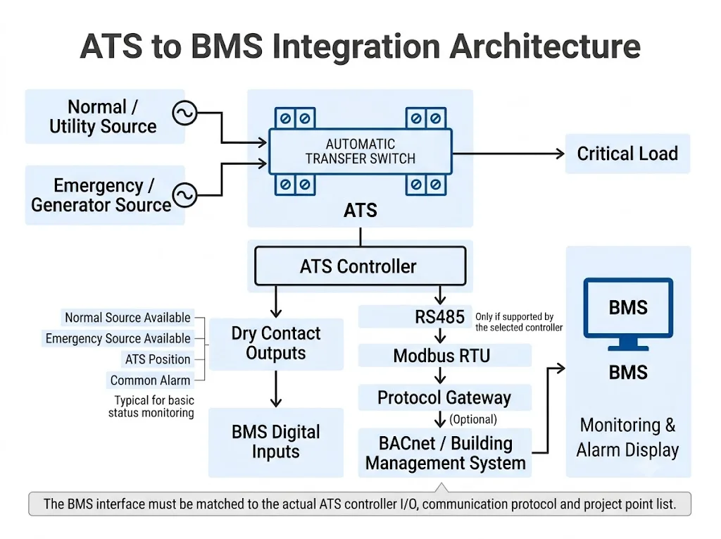
ATS BMS integration means connecting an automatic transfer switch to a building management system so the BMS can receive documented ATS status, alarm or operating information. The interface must be planned around the actual ATS controller and the project's required BMS points.
For LEEYEE compact 2P and 4P ATS projects, BMS functionality should be treated as a project-specific interface requirement, not assumed as a standard function of the compact transfer switch. First confirm what the building needs to monitor. Then confirm whether the selected ATS/controller provides the required contact outputs, communication interface or another approved integration method.
สารบัญ
Quick Answer: How Should an ATS Be Integrated with a BMS?
Start with the required BMS point list. Then verify whether the selected ATS/controller can provide each point through a physical contact, a documented communication interface or an approved external interface solution.
| Project Requirement | Possible Method | สิ่งที่ต้องยืนยัน |
|---|---|---|
| Basic local automatic transfer only | Standard compact ATS configuration | Voltage, current, poles and source arrangement |
| Source or position status to BMS | Dry / auxiliary contacts if provided | Actual terminal function and contact logic |
| Multiple ATS status points | RS485 / Modbus if controller supports it | Protocol, serial settings and register map |
| BACnet-based BMS | Native support or suitable gateway | Protocol mapping and gateway compatibility |
| Remote transfer or test control | Dedicated input or documented communication command | Controller support, authority and interlocks |
How This Guide Applies to a Compact 2P or 4P LEEYEE ATS
A compact ATS and a BMS communication system solve two different parts of the project. The ATS performs the source-transfer function. The BMS, when required, supervises selected operating information through interfaces provided by the ATS/controller.
The compact LEEYEE product format uses a local front operating interface with automatic/manual operation and local source or load status indication. These visible local functions should not be confused with an external BMS interface.
| What the Project Needs | How to Treat the Compact ATS | Next Confirmation |
|---|---|---|
| Automatic transfer between two sources | Core ATS function | Current, voltage, 2P/4P and electrical architecture |
| Local Auto / Manual operation | Local operating function | Confirm selected model specification |
| BMS reads source or switch status | Not assumed from the front panel | Confirm dedicated status outputs |
| RS485 / Modbus monitoring | Project-specific requirement | Confirm controller and communication documents |
| BACnet or BMS network integration | Project-specific integration | Confirm native interface or gateway architecture |
Why Does a Commercial Building BMS Need ATS Status?
A building management system gives operators central visibility of important equipment conditions. For an ATS, the useful question is usually: Which transfer-system conditions does the operator need to see remotely?
On suitably equipped controllers, documented information may include source availability, switch position, operating mode, alarm status or transfer-related information.[4][5] These manufacturer examples show what is possible on particular controllers. They do not prove that the same points are available on every compact ATS.
| การใช้งาน | Possible Monitoring Need | ATS Selection Meaning |
|---|---|---|
| Small commercial distribution board | Source and ATS-position status | Confirm whether external status outputs are required |
| Generator-backed auxiliary panel | Normal source, emergency source and transfer status | Confirm source-status and position feedback separately |
| OEM electrical control cabinet | ATS alarm or position sent to PLC/BMS | Define I/O requirement before model approval |
| Building-wide BMS project | Multiple ATS points over a communication network | Controller/interface requirement becomes critical |
What ATS Points Should the BMS Monitor?
Build the point list around the facility's actual operating needs. Then match each requested point to a real output, terminal or documented communication value.
| Example BMS Point | ความหมายของมัน | Possible Signal Method |
|---|---|---|
| มีแหล่งข้อมูลปกติ | Source 1 satisfies the controller's source-available logic | Contact or communication |
| มีแหล่งพลังงานฉุกเฉินพร้อมใช้งาน | Source 2 satisfies the controller's source-available logic | Contact or communication |
| โหลดบนแหล่งปกติ | Transfer position indicates connection to Source 1 | Auxiliary contact or communication |
| Load on emergency source | Transfer position indicates connection to Source 2 | Auxiliary contact or communication |
| Automatic / non-automatic mode | Operating mode of the controller | Controller-dependent |
| Common alarm | A defined ATS/controller alarm condition is active | Alarm contact or communication |
| Transfer / event information | Transfer state, event or cause information if documented | Communication-dependent |
This is an example engineering point list. Eaton and Socomec documentation demonstrate comparable source, operating-mode, switch-position and alarm information on specific controller families.[4][5]
What Is a Dry Contact in ATS BMS Integration?
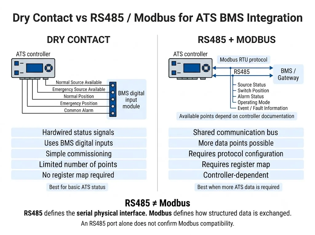
A dry contact is a voltage-free switching contact that changes between open and closed states. A BMS or PLC can monitor that state through a suitable digital input.
Dry contacts are useful when the project only needs a small number of simple status points. Typical examples may include source status, ATS position or a common alarm—but only if the selected ATS/controller actually provides those outputs.
Do not assume that the local indicator lamps on a compact ATS automatically have corresponding external dry-contact terminals.
Dry Contact vs RS485 / Modbus: Which Method Fits the Project?
| ปัจจัยในการตัดสินใจ | Dry Contact | RS485 / Modbus |
|---|---|---|
| Typical purpose | Basic binary status | Multiple documented data points |
| BMS connection | Digital inputs | Serial communication interface |
| Data quantity | Limited by physical outputs | Dependent on controller register map |
| Register map | Not required | Required |
| Commissioning | Verify contact state and NO/NC logic | Verify address, serial settings and register mapping |
| Compact LEEYEE ATS | Confirm output availability before order | Do not assume standard support |
RS485 is not the same thing as Modbus. Modbus is an application-layer messaging protocol, while serial implementations use a separate serial-line specification.[2]
Therefore, the presence of an RS485 terminal or connector alone would not prove that a controller supports the Modbus data required by the project. The communication protocol and register map must be verified.
How to Build an ATS BMS Point List
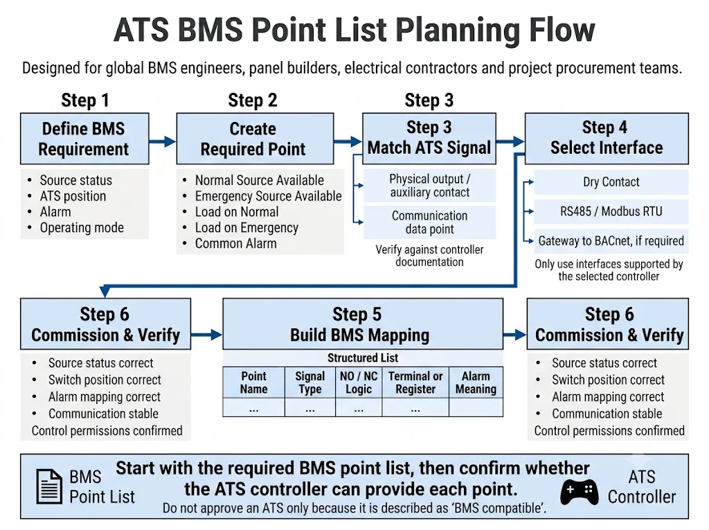
The best sequence is to start with what the BMS needs to know, then work backward to the ATS/controller.
-
Define the Required BMS Information
Identify the real operating need: source availability, transfer position, alarm, operating mode or another specific status.
-
Create a Clear Point Name
Use names such as “Normal Source Available,” “Emergency Source Available,” “Load on Emergency” or “ATS Common Alarm.”
-
Match the Point to a Real ATS Output
Identify the terminal, contact, controller output or communication register that provides the point. If no documentation supports it, do not assume it is available.
-
Select the Interface
Choose hardwired contacts, documented RS485/Modbus communication or another approved integration architecture according to the actual product capability.
-
Document the BMS Mapping
Record point name, signal type, NO/NC logic where relevant, terminal or register reference, alarm meaning and any configuration requirement.
-
Verify During Commissioning
Check that BMS indications correspond to the actual source condition, switch position and alarm state. Communication points must also match the final controller configuration.
Monitoring an ATS Is Not the Same as Controlling It
การตรวจสอบ
ทิศทางทั่วไป: ATS → BMS
- Source status
- Switch position
- Operating mode
- Alarm indication
- Event information if supported
Control
ทิศทางทั่วไป: BMS → ATS
- Transfer command
- Retransfer command
- Test command
- Mode-related command
- Other documented remote functions
Commercial ATS controller documentation shows that some advanced controllers provide both status registers and selected control functions.[4][5] This does not mean that those functions exist on every compact ATS.
What If the Building BMS Uses BACnet?
BACnet is defined by ANSI/ASHRAE Standard 135 as a data communication protocol for building automation and control networks.[3]
If a project uses BACnet, the ATS does not necessarily need native BACnet support. On systems that provide another documented protocol, a suitable gateway may sometimes be used. Eaton, for example, documents ATS communication architectures involving Modbus and building-management gateways.[4]
Do Not Confuse ATS Information with Generator Information
In a generator-backed system, the ATS and generator controller are separate information sources. Depending on the controller, an ATS may provide emergency-source status or generator-start-related information.[4][5]
Detailed generator information—such as engine conditions, fuel information, battery data or engine-controller faults—should not automatically be treated as ATS data. If these points are required, identify whether they come from the generator controller, ATS controller or another gateway.
How IEC 60947-6-1 Relates to the Project
IEC 60947-6-1:2026 applies to transfer switching equipment used to transfer a load between power-supply sources and includes provisions covering automatic transfer switching equipment and controllers.[1]
Compliance with an ATS product standard does not prove that a particular dry contact, Modbus register, BACnet interface or remote-control command is provided. These functions remain model- and controller-specific project items.
Common ATS BMS Integration Mistakes
Assuming the compact ATS front panel proves BMS capability
Local Auto/Manual controls and status lamps show local operating information. They do not prove the existence of corresponding remote contacts or communication registers.
Approving an ATS because a quotation says “BMS compatible”
The quotation should identify the actual BMS points, terminals or communication protocol. A general phrase is not enough for engineering approval.
Assuming RS485 automatically means Modbus
Confirm the actual protocol and register documentation rather than relying only on the physical interface.[2]
Creating the BMS point list after purchasing the ATS
Define the required monitoring points before the ATS/controller is finalized. Otherwise, the project may discover too late that an output or communication function is unavailable.
Using a compact ATS where the project requires a more advanced control architecture
If the project requires extensive network monitoring, remote commands, sophisticated event data, bypass functions or high-criticality system features, confirm whether the compact ATS architecture is appropriate before specifying it.
Before Ordering a LEEYEE ATS for a BMS Project
Send the project requirements before the ATS model is finalized. This allows the basic compact ATS requirement to be separated from any additional controller or interface requirement.
- กระแสไฟฟ้าที่ระบุ
- 2P or 4P requirement
- แรงดันไฟฟ้าและความถี่ของระบบ
- Normal source type
- Emergency source type
- Generator-backed or dual-utility arrangement
- Required BMS point list
- Required dry-contact outputs
- Required communication interface
- Required protocol
- RS485 / Ethernet requirement
- Modbus RTU / TCP requirement
- BACnet / gateway requirement
- Monitoring-only or remote-control requirement
- แผนภาพเส้นเดี่ยว
- BMS point schedule
Have a BMS Point List for Your ATS Project?
Send the required monitoring points, ATS current and pole configuration, source arrangement and communication requirements. LEEYEE can review whether the compact ATS requirement and the requested BMS interface are technically aligned before model confirmation.
ATS BMS Integration FAQ
Can a compact 2P or 4P ATS be connected to a BMS?
Potentially, but only when the selected ATS/controller provides the required external outputs or communication interface. Compact size alone does not confirm BMS capability.
Does the standard LEEYEE compact ATS include Modbus or BACnet?
Do not assume that Modbus, BACnet or another BMS communication interface is included as a standard function. If the project requires communication, confirm the exact controller/interface specification before model approval.
Do the front-panel status lights mean the same signals are available to the BMS?
Not necessarily. A local lamp or indicator confirms local status display only. A BMS requires a separate documented output, contact or communication point.
What ATS signals are normally useful to a BMS?
Typical project requirements may include normal-source availability, emergency-source availability, transfer position, operating mode and alarm status. Actual availability depends on the selected ATS/controller.
What is the difference between ATS dry contacts and Modbus?
A dry contact provides a simple open/closed electrical status for a digital input. Modbus can exchange multiple structured data points when the controller supports the protocol and provides a documented register map.
Is RS485 the same as Modbus?
No. RS485 describes the serial physical interface, while Modbus defines how structured messages are exchanged. The presence of RS485 alone does not confirm Modbus support.[2]
Can a BMS remotely operate a compact ATS?
Only if the selected ATS/controller explicitly provides and documents a suitable remote-control function. Do not infer remote transfer capability from the presence of Auto/Manual controls or from a communication port.
Does the ATS provide all generator data to the BMS?
No general assumption should be made. Detailed generator telemetry may come directly from the generator controller rather than through the ATS.
เอกสารอ้างอิง
- คณะกรรมการเทคโนโลยีกำลังไฟฟ้านานาชาติ (IEC). IEC 60947-6-1:2026 — Low-voltage switchgear and controlgear — Part 6-1: Multiple function equipment — Transfer switching equipment. หน้าการเผยแพร่อย่างเป็นทางการของ IEC .
- Modbus Organization. Modbus Application Protocol Specification และ Modbus Serial Line Protocol and Implementation Guide. Official Modbus specifications .
- ASHRAE. ANSI/ASHRAE Standard 135-2024 — BACnet: A Data Communication Protocol for Building Automation and Control Networks. ASHRAE standards information .
- อีตัน. ATS Controllers and Remote Annunciators Design Guide, DG140004EN. The guide documents examples of ATS controller communication, Modbus data, gateways and building-management-system connectivity. Eaton ATS controller design guide .
- Socomec. ATyS Communication / Modbus Tables. Official controller documentation includes examples of operating mode, switch position, source status, generator-start-relay state, alarm/fault status and transfer information. Socomec ATyS communication table .
