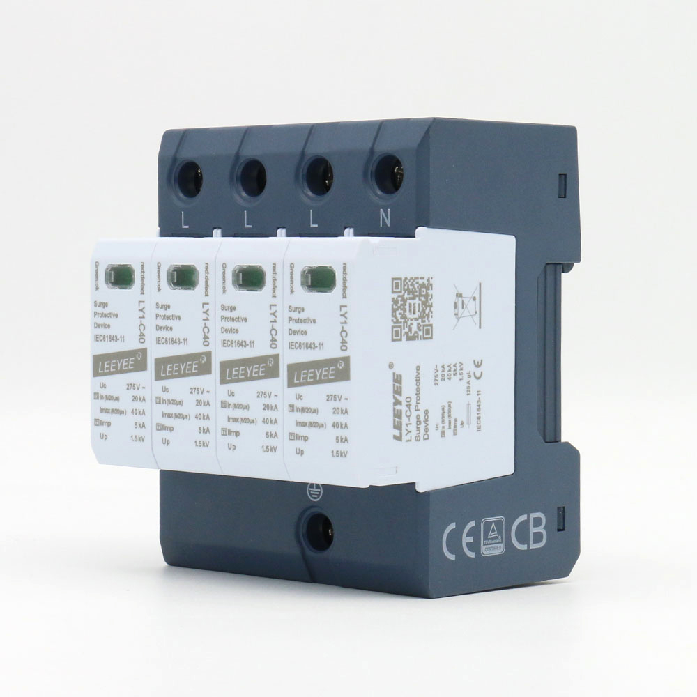
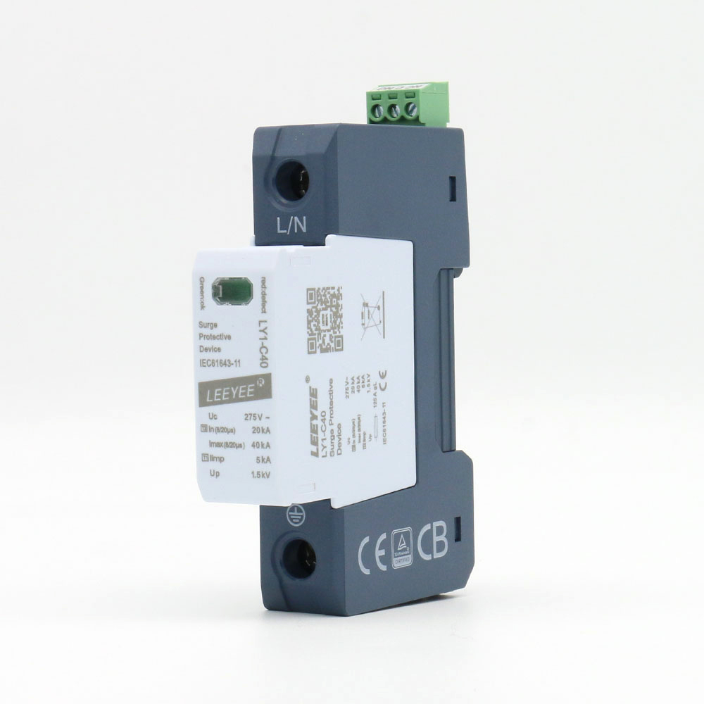
LY1-C40/1(S)
Single-pole Type 2 AC SPD
- Uc options75 / 150 / 275 / 320 / 385 / 440V AC
- In / Imax20kA / 40kA · 8/20μs
- ProtectionHigh-energy MOV · Pluggable module
- Up0.4–2.0kV, depending on Uc
- OptionsVisual indication · Remote contact (S)
Type 2 SPDs for distributors, panel builders, contractors, OEM brands and electrical projects. Confirm Uc, pole configuration, protection mode and model-specific documents before ordering.
A Type 2 keyword is only the first filter. Final selection depends on nominal voltage, Uc, earthing system, pole arrangement, Up and external backup protection.
Use Type 2 duty at distribution or equipment-panel level for 8/20μs lightning-induced and switching transients. Then select the correct MOV or MOV + GDT arrangement for the actual conductors and earthing system.
| System requirement | Starting configuration | Main confirmation |
|---|---|---|
| Single protection path | 1P LY1-C40/1(S) | Protected conductor, PE path, Uc, Up and short-circuit conditions. |
| Two-pole AC circuit | 2P LY1-C40/2(S) | L-PE / N-PE arrangement, earthing design and external backup protection. |
| Three-phase without neutral | 3P LY1-C40/3(S) | Three protected phase paths, Uc, Up and system earthing arrangement. |
| Single-phase plus neutral | 1P+N LY1-C40/1(S)+1 | L-N MOV path, N-PE GDT path and TT/TN-S suitability. |
| Three-phase plus neutral | 3P+N LY1-C40/3(S)+1 | 3+1 protection mode, L-N voltage and N-PE path. |
| Four-pole arrangement | 4P LY1-C40/4(S) | 4+0 versus 3+1 requirement, Uc/Up and DIN space. |
Do not select by pole count alone. Send the single-line diagram, TT/TN-S/TN-C information and system voltage when the network arrangement is uncertain.
Choose a representative model, then confirm the exact Uc, protection mode, remote contact, backup protection and document scope.
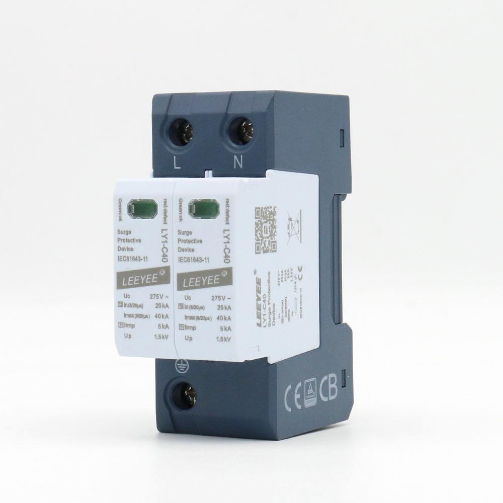
Single-pole Type 2 AC SPD
Two-pole Type 2 AC SPD
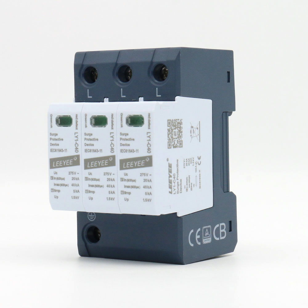
Three-pole Type 2 AC SPD
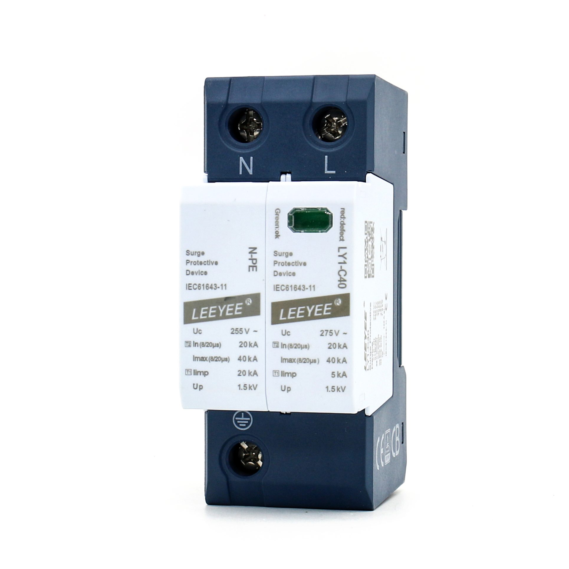
1P+N coordinated Type 2 SPD
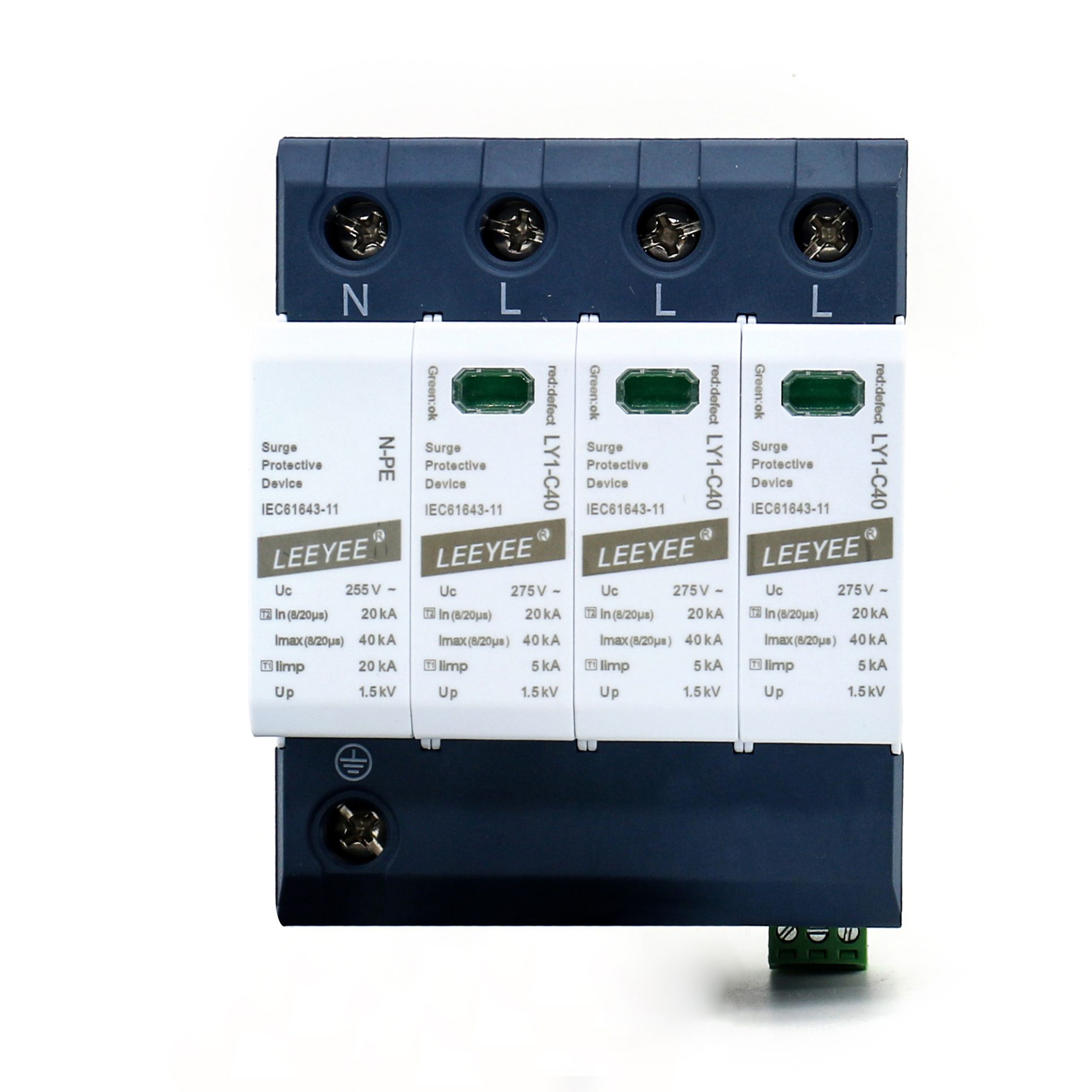
3P+N coordinated Type 2 SPD
Four-pole Type 2 AC SPD
Confirm the installation point, upstream lightning-protection concept and downstream equipment withstand before selecting the final model.
The model should be reviewed as part of the complete distribution, earthing and overcurrent-protection design.
Use these only as an initial review. Final selection must follow the actual protected path, voltage tolerance, TOV conditions and equipment withstand level.
Do not select from kA or nominal voltage alone.
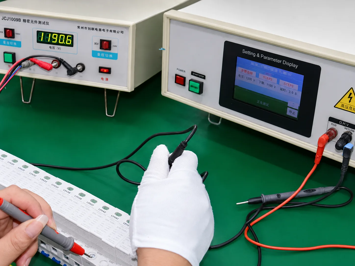
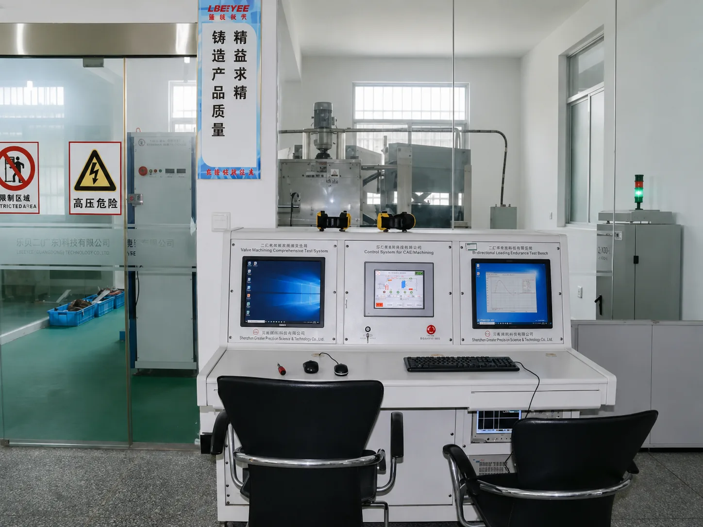
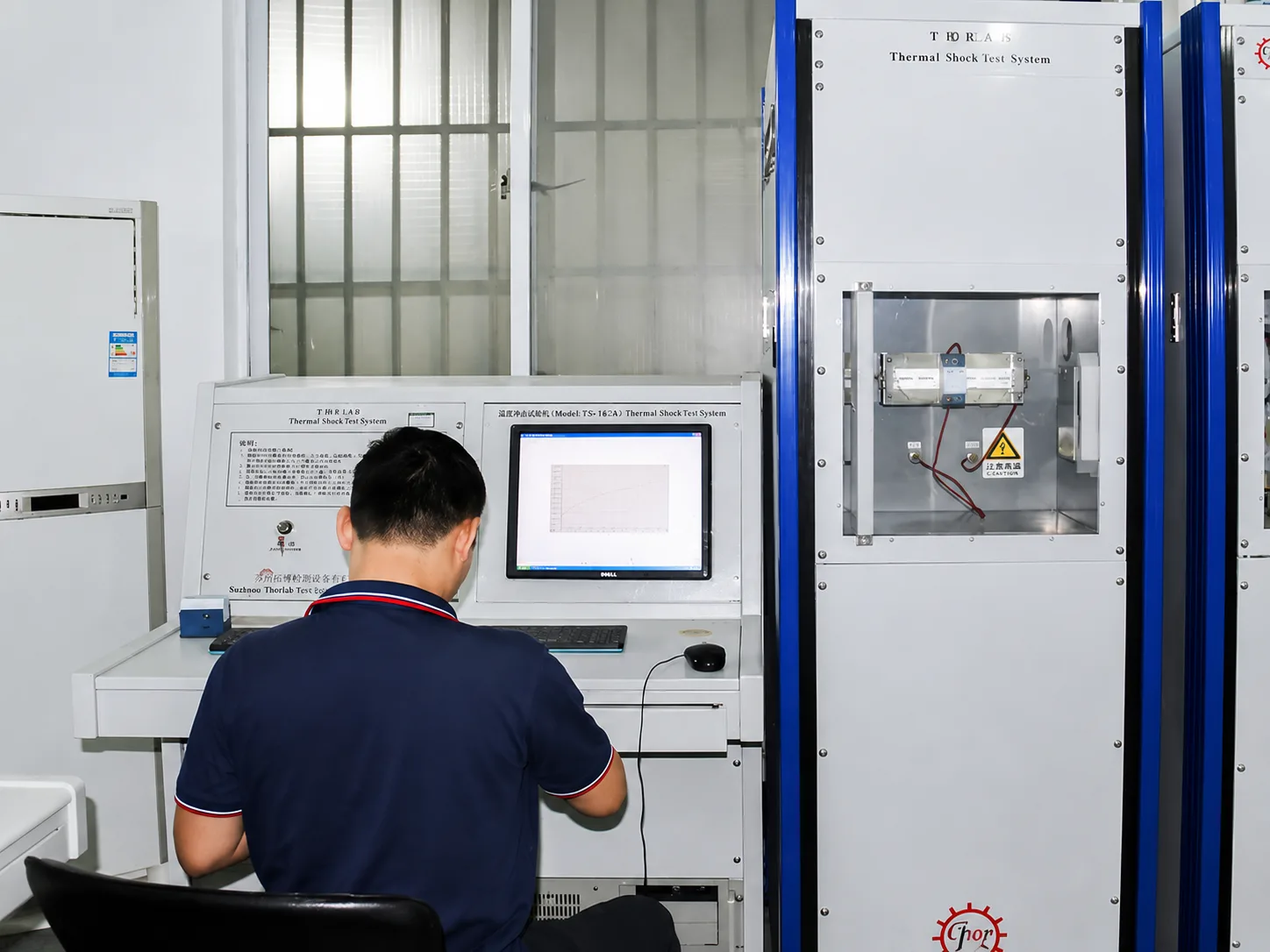
Component, impulse and thermal checks support validation. They do not replace confirmation that the exact model and branding are covered by the submitted document.
Component checks support review of clamping behaviour, leakage-related parameters and batch consistency.
Type 2 selection should verify In, Imax and the tested protection path.
Thermal behaviour and disconnection matter when MOVs age or face abnormal overvoltage.
Reference files must not be treated as universal coverage for every voltage, pole arrangement, suffix or private-label configuration.
Certificate and report coverage depends on the exact model, Uc, pole configuration, suffix, brand and manufacturer. Request model-specific confirmation before project approval.
Do not approve a document from the logo alone.
Confirm the electrical base model first. Then align the logo, model name, label, packaging, instructions and applicable document scope before production.
A Type 2 SPD is a Class II surge protective device evaluated primarily with an 8/20μs discharge-current waveform. It is commonly selected for distribution boards, control cabinets and downstream AC systems.
In is the nominal discharge current used for repeated Type 2 duty, while Imax is the maximum 8/20μs discharge-current value stated for the device. Neither value is the 10/350μs Iimp used for Type 1 duty.
Start with the earthing system and required protection paths. Confirm whether the project needs phase-to-PE MOV paths, a coordinated L-N and N-PE arrangement, or another topology. Then match Uc, Up, poles and document scope.
Use the actual continuous voltage across the protected path, including normal tolerance and expected temporary overvoltage conditions. Then compare the resulting Up with the equipment withstand level.
That depends on the lightning-protection concept and installation risk. Where partial direct lightning current may enter, a Type 1 or Type 1+2 assessment is required upstream.
No. External backup fuse or MCB coordination must still be confirmed from the exact model data, prospective short-circuit current and upstream protective device.
Provide nominal voltage, earthing system, pole arrangement, estimated quantity, remote-contact requirement, required documents, timing and any single-line diagram or BOM.
Send the essential project details. LEEYEE can review Type 2 duty, Uc, poles, protection mode, backup-protection questions and model-specific document availability.
Required fields help filter incomplete retail or non-project requests.