
Solar monitoring surge protection must cover more than the PV AC and DC power circuits. A surge can also enter through an inverter communication port, an RS485 bus, an outdoor Ethernet cable, a weather-station sensor line or the data logger power supply.
A PV plant may continue generating after part of its monitoring network fails. However, the EPC or O&M team may lose inverter alarms, performance data, weather measurements and remote fault visibility. This guide explains how to review those paths without turning the decision into a generic PV SPD selection exercise.
Table of Contents
Quick Answer: Does a Solar Monitoring System Need Surge Protection?
Solar monitoring surge protection should be assessed line by line. Review every external copper path connected to the monitoring system: AC or DC power, RS485 or Modbus RTU, Ethernet or Modbus TCP, PoE, analogue sensor loops and pulse or digital inputs.
A power SPD cannot replace a signal SPD. An RS485 SPD cannot replace an Ethernet protector. Outdoor wiring, inter-building cables and lines crossing different lightning protection or equipotential zones deserve particular attention.
The final configuration must match the real interface voltage, conductor arrangement, transmission rate, cable route, earthing design and equipment instructions.[1][2][3]
| Circuit | Typical Equipment | Protection to Assess |
|---|---|---|
| RS485 / Modbus RTU | Inverter, meter, data logger, smart sensor | RS485-compatible signal SPD matched to the actual wiring and signal limits |
| Ethernet / Modbus TCP | Logger, switch, SCADA gateway, router | RJ45 or industrial Ethernet SPD matched to category, speed and PoE use |
| Low-voltage DC power | Data logger, sensor gateway, router | DC power SPD matched to maximum operating voltage and load conditions |
| Analogue or pulse signal | Pyranometer, temperature, rain and wind sensors | Signal SPD matched to output type, signal range, loop wiring and frequency |
| AC supply | Monitoring cabinet, AC adapter, auxiliary supply | AC SPD selected separately for the power system and installation position |
Solar Monitoring Surge Protection Starts with the Complete Signal Path
A solar monitoring system is a chain of devices and interfaces, not one communication cable.
Depending on the project, the chain may include inverter communication terminals, energy meters, string monitoring units, a data logger, a communication gateway, an Ethernet switch, a router, a weather station and a SCADA connection.
Utility-scale monitoring may also include irradiance, temperature, wind, rain and albedo sensors distributed across the array. Each device can have a separate power input and one or more communication or measurement outputs.
IEC 61724-1 describes terminology, equipment and methods for PV performance monitoring and defines monitoring system classes. It provides the monitoring context, but it does not mean that one SPD design fits every sensor or communication architecture.[4]
Draw the complete monitoring topology before selecting any SPD. List each cable’s source, destination, physical interface, supply voltage and route. This prevents a project from protecting only the central cabinet while leaving the outdoor device port exposed.
For the wider AC-side, DC-side and system-level protection concept, review the separate solar PV surge protection guide. The present page focuses specifically on monitoring, communication and data-acquisition circuits.
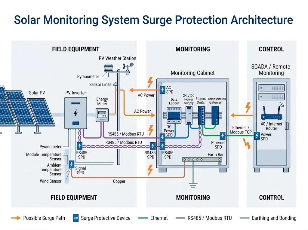
Where Can Surges Enter a PV Monitoring Network?
A nearby lightning event can induce transient voltages in long conductors. Potential differences can also appear between equipment zones, earthing points or conductive structures.
IEC 62305-4 addresses surge protection measures for electrical and electronic systems against lightning electromagnetic impulse. It includes design, installation, inspection, maintenance and testing considerations.[1]
For a solar monitoring system, the most common conductive entry paths are:
- the monitoring cabinet’s AC supply;
- the 24 V DC or other low-voltage supply feeding the data logger, gateway or sensor;
- an RS485 bus between inverters, meters, sensors and the logger;
- an Ethernet copper cable between a logger, switch, router or SCADA cabinet;
- weather-station power and signal cables;
- analogue, pulse and digital input wiring;
- cables crossing between buildings, outdoor structures or different equipotential zones.
A practical protection concept treats every cable crossing into a protected zone as a possible coupling path. Power, measurement, control and information-technology lines must all be considered—not only the PV string circuit.[6]
Select the SPD by the Physical Interface, Not Only the Protocol Name
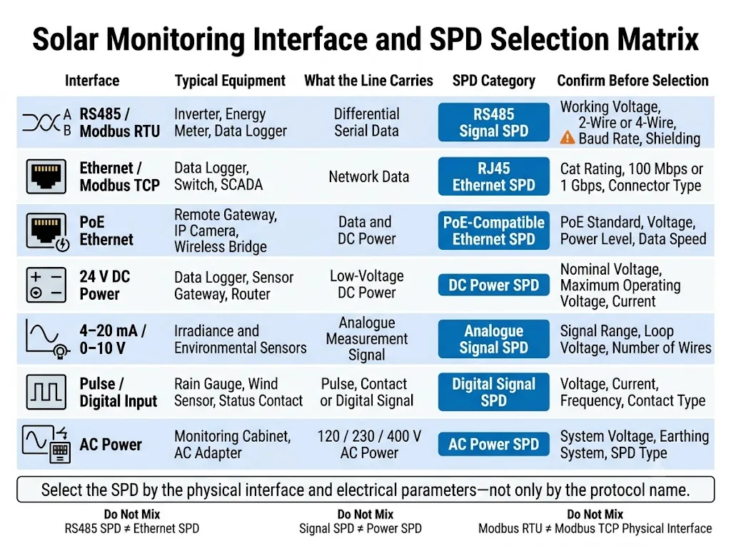
“Modbus”, “weather station” or “data logger” is not enough information to select a protection device.
The official Modbus specification defines Modbus as an application-layer messaging protocol that can operate over different buses and networks. It can be implemented over TCP/IP on Ethernet or through asynchronous serial media such as EIA/TIA-485.
Modbus RTU and Modbus TCP therefore normally require different physical-interface protection.[5]
IEC 61643-21 covers SPDs connected to telecommunications and signalling networks. The 2025 edition also includes networks that provide power on the same line, such as PoE. IEC 61643-22 gives principles for selection, operation, location and coordination of these SPDs.[2][3]
The final column is the most important for project approval. The interface name alone does not confirm compatibility.
| Interface | Typical Equipment | SPD Category | Confirm Before Selection |
|---|---|---|---|
| RS485 / Modbus RTU | Inverter, meter, logger, smart sensor | RS485 signal SPD | Working voltage, two-wire or four-wire layout, conductor count, baud rate, signal reference and shield |
| Ethernet / Modbus TCP | Logger, network switch, SCADA gateway | RJ45 or industrial Ethernet SPD | Connector, cable category, data rate, protected pairs, shielding and installation environment |
| PoE Ethernet | Remote gateway, IP camera, wireless bridge | PoE-compatible Ethernet SPD | PoE method, operating voltage, power level, data rate and pair configuration |
| 24 V DC power | Logger, router, sensor gateway | DC power SPD | Nominal voltage, maximum continuous operating voltage, current and conductor arrangement |
| 4–20 mA / 0–10 V | Irradiance and environmental sensors | Analogue signal SPD | Signal range, loop supply, accuracy requirement, wire count and grounding method |
| Pulse / digital input | Rain gauge, wind sensor, status contact | Digital signal SPD | Voltage, current, pulse frequency, contact type and common conductor |
| AC power | Monitoring cabinet, AC adapter | AC power SPD | System voltage, earthing arrangement, installation point, upstream protection and required SPD type |
Selection conclusion: choose the SPD by the physical interface and electrical parameters—not only by the protocol or equipment name.
RS485 SPD ≠ Ethernet SPD. Signal SPD ≠ power SPD. The protection circuit must preserve the wanted signal while limiting the transient. Confirm the interface datasheet before approval.
How Should RS485 and Modbus RTU Lines Be Protected?
RS485 is widely used between PV inverters, meters, data loggers and intelligent weather sensors. The line may run through outdoor cable trays, underground ducts or several inverter stations. Those routes can expose both connected ports to induced surges and potential differences.
Confirm the real RS485 wiring first
Do not select an SPD from the words “RS485” or “Modbus RTU” alone. Check the device wiring diagram and confirm:
- two-wire or four-wire communication;
- the number of conductors requiring protection;
- normal and maximum working voltage at the interface;
- whether a signal reference conductor is used;
- shield construction and termination method;
- baud rate and acceptable line capacitance;
- terminal layout and connector type;
- indoor DIN-rail or outdoor enclosure installation.
Preserve communication performance
A signal SPD becomes part of the transmission path. Its protective circuit, capacitance, insertion loss and conductor arrangement must be compatible with the intended bus.
A model suitable for a low-speed analogue loop may not be suitable for a higher-speed serial network. Manufacturers provide different protective circuits for high-speed Ethernet, RS485 and analogue or digital interfaces because their electrical and transmission requirements differ.[7]
Keep bus design and surge protection as separate checks
Termination resistors, biasing, topology and node limits are communication-design issues. An SPD does not correct a poorly designed RS485 network.
After installation, the EPC should verify normal communication, error rate and device polling under the final cable layout. For a deeper interface-specific review, see the RS485 surge protection device selection guide.
Send the supplier the inverter or logger communication diagram—not only the protocol name. Ask for the SPD connection drawing, rated signal voltage, protected conductors and relevant transmission data.
How Should Ethernet, Modbus TCP and PoE Be Protected?
Modbus TCP uses Ethernet as its network medium. An Ethernet SPD must therefore match the cabling category, connector arrangement, network speed and whether the cable also carries power.
Confirm these Ethernet parameters
- copper Ethernet or fibre-optic link;
- RJ45 or another industrial connector;
- required data rate and cabling category;
- number of protected pairs;
- whether PoE is present;
- PoE voltage and power requirements;
- shielded or unshielded cabling;
- indoor, outdoor or inter-building route.
IEC 61643-21:2025 explicitly covers signalling networks that can provide power on the same line, including PoE. That does not mean every PoE SPD suits every PoE system. Compatibility still has to be confirmed from the device and network specifications.[2]
Where a fibre link replaces a conductive data cable, the optical path does not carry a conductive surge in the same way as copper. However, transceiver power supplies, conductive armour and associated cabinet wiring still require review.
For interface-specific selection factors, continue to the RJ45 surge protector selection guide.
Do not assume that an RJ45 form factor proves compatibility. Confirm bandwidth, pair configuration, PoE support, shielding and the protected equipment’s maximum interface voltage before approving a model.
How Should PV Weather-Station Sensor Lines Be Protected?
A “weather-station SPD” is not one universal product. The correct protection depends on each sensor’s supply and output circuit.
RS485 Sensors
Smart pyranometers, integrated weather sensors and multi-parameter stations may use RS485 or Modbus RTU. Review them with the same interface checks used for inverter communication.
Analogue Sensors
Examples include 4–20 mA, 0–10 V, millivolt and resistance-based temperature circuits. Confirm signal range, loop supply, wire count and measurement accuracy.
Pulse or Digital Inputs
Rain gauges, wind sensors and status contacts may use pulses, dry contacts or powered digital signals. Confirm voltage, current, frequency and contact arrangement.
Utility-scale monitoring stations can include many sensors with different topologies and cable lengths. Campbell Scientific’s solar monitoring surge-protection paper shows that remote sensors, data acquisition, cable shielding and local grounding must be considered as one system.
The same document recommends following each equipment manufacturer’s grounding instructions because sensor designs differ.[8]
Protect sensor power and signal circuits separately
A sensor can have one cable carrying both DC power and communication, or separate supply and signal conductors. A protective device must match the actual pin assignment.
Never assume that a connector adapter preserves the correct protected conductor arrangement without checking the wiring drawing.
Build a sensor schedule listing the model, supply, output, pin assignment, cable length and mounting location. Select protection from this schedule rather than from the sensor name alone.
Protect Data Logger Power and Inverter Communication Ports Separately
Data logger power input
A data logger may be supplied from 230 V AC, 24 V DC, a DC/DC converter, a battery system or a small independent solar supply. The power entry is a separate surge path from the measurement and communication terminals.
Some data loggers or monitoring stations include internal surge immunity or protective components. Built-in protection should be treated as equipment-specific evidence, not as proof that an external SPD is unnecessary.
Confirm the equipment’s declared immunity, installation manual and the project’s expected surge environment.[8]
Inverter communication ports
The review should cover RS485 A/B terminals, Ethernet ports, meter interfaces, digital inputs, remote-control terminals and communication gateways.
This section concerns the communication interface only. AC-side and PV DC-side inverter protection require separate project checks.
An AC or DC power SPD cannot protect an RS485 or Ethernet port unless a purpose-designed multi-service device explicitly provides coordinated protection for both circuits. IEC 61643-22 recognises multi-service SPDs, but applicable circuit ratings and coordination still require verification.[3]
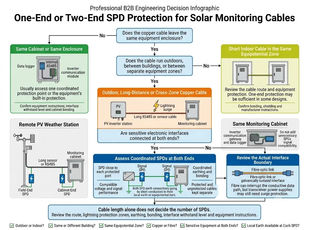
Should Communication SPDs Be Installed at One End or Both Ends?
There is no universal cable-length rule that answers this question for every solar project.
IEC 61643-22 addresses SPD location and coordination for telecommunications and signalling networks. The lightning protection zone concept also treats cables crossing zone boundaries as paths that must be included in equipotential bonding with suitable, coordinated protection.[3][6]
Give priority to a two-end assessment when:
- the cable runs outdoors or between separate structures;
- the field device and monitoring cabinet are in different equipotential zones;
- the route is long or exposed alongside PV structures, fences or cable trays;
- a weather station connects to a remote control cabinet;
- sensitive electronic ports are connected at both ends;
- each end has a suitable local bonding point and coordinated SPD installation can be achieved.
One coordinated protection point may be considered when:
- the connection stays inside one enclosure;
- the cable is short and remains in the same equipotential zone;
- the connected equipment includes documented, coordinated internal protection;
- the interface is galvanically isolated or converted to fibre, subject to remaining power and armour checks.
These are engineering screening conditions, not automatic approval rules. Review the route, lightning protection zones, earthing, bonding, interface withstand level and equipment instructions.
Installation, Earthing and Shielding Determine SPD Performance
A correctly selected SPD can still provide poor protection if it is installed with a long, indirect discharge path or if protected and unprotected cables are mixed together.
- Place the SPD close to the protected interface. Keep the unprotected cable section between the zone entry and SPD as short as practical.
- Use a short, direct bonding connection. Route the SPD connection to the designated local earth or equipotential bar according to the product instructions.
- Separate protected and unprotected wiring. Do not run them together for a long distance after the SPD, because recoupling can reduce the benefit of the protection concept.
- Follow the equipment manufacturer’s shield instructions. Single-end, multi-point or housing connections can differ by sensor and system design.
- Coordinate SPDs at zone boundaries. Devices at different locations must be selected and installed as one protection system, not as isolated components.
- Verify communication after installation. Confirm polling, data quality, network speed and alarms under the final wiring arrangement.
Phoenix Contact’s technical guide recommends dividing a structure into lightning protection zones, including zone-crossing cables in local equipotential bonding through suitable SPDs, using short SPD connections and separating protected and unprotected cables.[6]
Do not apply one shield-termination rule to every pyranometer, RS485 device or monitoring cabinet. Sensor construction, isolation, mounting and manufacturer instructions can change the correct method.[8]
Three Solar EPC Application Scenarios
1. Commercial rooftop PV system
Several rooftop inverters communicate through RS485 to a data logger in an electrical room. The logger then connects to the building network by Ethernet.
Review: the outdoor-to-indoor RS485 route, protection at the zone entry and sensitive ports, the logger’s auxiliary supply and the copper Ethernet connection. Keep the inverter AC/DC SPD design separate from the monitoring-interface review.
2. Utility-scale solar plant
Multiple inverter stations, energy meters, remote weather sensors and SCADA equipment may span different equipment zones. A fibre backbone may be used for long-distance communication while copper remains at field-device level.
Review: every copper segment, field and cabinet bonding points, sensor pin assignments, local auxiliary supplies, interface coordination and spare-module strategy. Include the monitoring topology in the project’s protection-zone review.
3. Remote PV weather station
A standalone station may include a small solar supply, battery, data logger, RS485 sensors and a cellular router. Sensor cables can extend across the array while the enclosure remains exposed outdoors.
Review: sensor-side and enclosure-side protection, supply circuits, router power, antenna-system requirements, enclosure environmental rating and the manufacturer’s grounding method. Do not assume that one SPD at the enclosure protects every remote sensor.
Common Solar Monitoring Protection Mistakes
| Mistake | Why It Creates Risk |
|---|---|
| Protecting only PV DC circuits | The logger, weather station and communication ports remain connected to other conductive entry paths. |
| Buying a “Modbus SPD” without interface data | Modbus may operate over RS485 or Ethernet. The physical layer determines the protective circuit. |
| Using one SPD for power and data | Power and signal circuits have different voltage, current and transmission requirements. |
| Using an RS485 SPD on Ethernet | Pair configuration, bandwidth, connector and PoE requirements are different. |
| Protecting only the cabinet end by habit | A remote field device may remain exposed, especially across outdoor or cross-zone copper wiring. |
| Ignoring the logger power input | Communication protection does not limit a transient entering through the auxiliary supply. |
| Long or indirect SPD bonding | Additional conductor inductance can increase the voltage appearing at protected equipment during a fast transient. |
| Applying one shield rule to every sensor | Grounding and housing arrangements differ. The wrong method can create noise or an unsuitable surge path. |
What Should a Solar EPC Confirm Before Ordering?
A reliable solar monitoring surge protection schedule starts with a cable and interface list, not a general request for “solar SPDs”.
Project information checklist
- PV plant type and monitoring architecture
- Device manufacturer and model
- Source and destination of each cable
- Modbus RTU, Modbus TCP or another protocol
- RS485 two-wire or four-wire arrangement
- Normal and maximum interface voltage
- Signal reference and shield arrangement
- Baud rate or Ethernet data rate
- Ethernet category and PoE requirement
- Sensor supply and output type
- Cable length and routing environment
- Indoor, outdoor or inter-building installation
- Lightning protection and equipotential zones
- Local earthing or bonding point at each end
- DIN-rail, panel or field-enclosure mounting
- Required standard, report or certificate scope
- Remote signalling and replaceable module needs
- Quantity, labelling and OEM documentation needs
Recommended EPC interface schedule
Use one row for each physical cable segment. Do not combine several interfaces into one line.
| From / To | Interface | Voltage / Speed | Route | Protection Point | Project Note |
|---|---|---|---|---|---|
| Inverter station → data logger | RS485 / Modbus RTU | From device datasheets | Outdoor / indoor / cross-zone | Field end, cabinet end or both after review | Confirm wire count, shield and local bonding |
| Weather sensor → met enclosure | RS485, analogue or pulse | From sensor datasheet | Array-mounted outdoor cable | Close to protected interfaces | Confirm pin assignment and sensor grounding |
| Data logger → SCADA switch | Ethernet / Modbus TCP | Category, rate and PoE status | Same room / inter-building / outdoor | At cable zone entries after review | Consider fibre for suitable long cross-zone links |
Procurement conclusion: approve the SPD only after the device datasheet, cable route, earthing method and installation drawing agree with the proposed model.
Send the monitoring topology, device models, interface voltages, cable routes and earthing information. LEEYEE can help review the required SPD categories and identify the project details that still need confirmation before model approval.
LEEYEE is a specialized surge protection and low-voltage protection supplier. CNSPD is LEEYEE’s surge protection-focused platform for global technical buyers.
Frequently Asked Questions
Does every solar monitoring system need a communication SPD?
Not automatically. The decision depends on conductive cable routes, lightning exposure, zone boundaries, earthing, equipment immunity and project requirements. Outdoor or cross-zone copper lines generally deserve a stronger protection review than short internal wiring.
Is a Modbus surge protector the same as an RS485 surge protector?
Not necessarily. Modbus is an application-layer protocol. Modbus RTU commonly uses RS485, while Modbus TCP uses Ethernet. Select the SPD from the physical interface and electrical parameters, not from the protocol name alone.[5]
Can an RS485 SPD be used for Ethernet?
No general substitution should be assumed. Ethernet has different pair arrangements, bandwidth, connector and possible PoE requirements. Use an SPD designed and documented for the actual Ethernet network.
Should RS485 SPDs be installed at both ends?
Both ends should be assessed when the cable is outdoor, long, inter-building, cross-zone or connected to sensitive equipment at both ends. A short cable inside one enclosure may need a different solution. Confirm zone boundaries, bonding, local earth points and equipment instructions before final approval.
Does a data logger need a separate power SPD?
The power input is a separate surge path from communication and sensor terminals. Review the actual AC or DC supply, maximum operating voltage, upstream protection and the logger manufacturer’s immunity information.
How do I select an SPD for a pyranometer or weather sensor?
Confirm the sensor’s supply, output type, signal range, wire count, pin assignment, cable shield and grounding method. A digital RS485 pyranometer, a millivolt sensor and a 4–20 mA transmitter require different interface reviews.
Can fibre remove the need for all surge protection?
No. Fibre can interrupt a conductive data path, but transceiver power supplies, cabinet power, metallic armour and other connected copper circuits may still require protection and bonding review.
What documents should an EPC request before approving a signal SPD?
Request the product datasheet, connection diagram, protected conductor arrangement, rated signal voltage, transmission data, test-standard information, environmental limits and certificate or report scope where required. Check these documents against the actual device and cable schedule.
References
- International Electrotechnical Commission, IEC 62305-4:2024, Protection against lightning – Part 4: Electrical and electronic systems within structures.
- International Electrotechnical Commission, IEC 61643-21:2025, Low-voltage surge protective devices – Part 21: Surge protective devices connected to telecommunications and signalling networks – Performance requirements and testing methods.
- International Electrotechnical Commission, IEC 61643-22:2015, Low-voltage surge protective devices – Part 22: Surge protective devices connected to telecommunications and signalling networks – Selection and application principles.
- International Electrotechnical Commission, IEC 61724-1:2021, Photovoltaic system performance – Part 1: Monitoring.
- Modbus Organization, MODBUS Application Protocol Specification V1.1b3, 2012.
- Phoenix Contact, Fundamentals for Surge Protection: From the Generation of Surge Voltages to a Comprehensive Protection Concept.
- Phoenix Contact, Surge Protection for Information Technology.
- Campbell Scientific, SunSentry G2 Surge Protection.
