
ATS Working Principle & Sequence of Operation
An automatic transfer switch does more than move electrical contacts from one power source to another. In a generator-backed system, the ATS must monitor the preferred source, decide whether that source remains acceptable, coordinate a generator start request, verify the alternate source, transfer the load, monitor utility recovery, retransfer the load and complete the generator cooldown sequence.
For panel builders, generator integrators, distributors, OEM buyers and project engineers, understanding this sequence is important because sensing functions, delays, transition method, interlocking and generator-control interfaces directly affect the ATS configuration required for a project.
Table of Contents
Quick Answer: How Does an Automatic Transfer Switch Work?
An automatic transfer switch works as a controlled power-transfer sequence. It monitors the preferred source and, if that source becomes unacceptable, follows programmed logic before transferring the load. In a utility-to-generator system, the controller can request generator start, verify that the alternate source has reached acceptable voltage and frequency conditions, and then command the switching mechanism to transfer the load. When utility power returns and satisfies the required return logic, the ATS retransfers the load and the generator can complete its cooldown sequence before stopping. [1] [3]
- Monitor utility
- Detect unacceptable source
- Request generator start
- Verify backup source
- Transfer load
- Monitor utility return
- Retransfer load
- Generator cooldown
- ATS operation is a sequence, not one switching movement.
- Generator start time and ATS switching time are different.
- The controller decides when to transfer; the switching mechanism performs the transfer.
- Retransfer normally occurs only after the preferred source satisfies the required return logic.
- Open, delayed and closed transition produce different load-transfer behaviour.
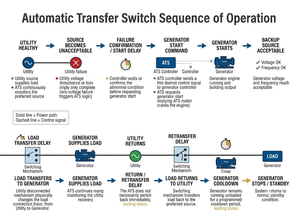
Automatic Transfer Switch Sequence of Operation: Step by Step
The easiest way to understand the ATS working principle is to follow one complete utility failure and recovery cycle. Exact timer names, source-acceptance thresholds and available functions vary by controller, so the final operating sequence must always be verified against the selected ATS, generator documentation and project requirements. [2] [3]
| Stage | What Happens | Buyer Meaning |
|---|---|---|
| 1. Normal operation | Utility or another preferred source supplies the load while the ATS monitors source conditions. | The controller must match the source arrangement and electrical system. |
| 2. Source becomes unacceptable | The controller detects that the preferred source is outside its configured acceptable conditions. | A transfer condition does not have to mean complete zero-voltage failure. |
| 3. Failure confirmation / start logic | After applicable confirmation or start delay, the ATS controller requests generator start. | Confirm generator-start interface and required timing functions. |
| 4. Generator starts | The generator controller carries out cranking, engine start and electrical output build-up. | The ATS normally requests start; it does not mechanically crank the engine. |
| 5. Backup source becomes acceptable | Generator voltage and frequency satisfy the source-acceptance logic required for transfer. | A running engine does not automatically mean the source is ready for the load. |
| 6. Load transfer | The controller commands the switching mechanism to connect the load to the alternate source. | Transition architecture determines whether the load sees a break or controlled overlap. |
| 7. Backup operation | The generator supplies the load while the ATS continues monitoring both source conditions. | The ATS remains active after transfer and watches for utility recovery. |
| 8. Utility returns | The controller detects that the preferred source has returned and evaluates whether it is acceptable. | Utility voltage reappearing does not necessarily cause immediate retransfer. |
| 9. Retransfer | After applicable return logic or retransfer delay, the switching mechanism reconnects the load to the preferred source. | Return timing helps avoid unnecessary cycling during unstable recovery. |
| 10. Cooldown and standby | The generator may continue running unloaded for a configured cooldown period before stopping. | Cooldown is part of the generator-control sequence, not the physical transfer time. |
Procurement conclusion: ask for the complete ATS sequence of operation, not only a quoted “transfer time.”
What Does the ATS Monitor Before It Transfers?
A simplified explanation often says that an ATS “detects a power failure.” In practice, the controller determines whether a source is acceptable or unacceptable according to the sensing functions and settings provided by that controller.
Voltage and frequency are fundamental monitored parameters in many automatic transfer systems. More capable controllers can also monitor conditions such as undervoltage, overvoltage, underfrequency, overfrequency, phase loss, phase reversal or voltage unbalance. Eaton's ATC-900 is one example of a controller providing these functions. [1] [2]
Buyer meaning
Do not define the requirement only as “transfer when power goes off.” Confirm which electrical conditions must make a source unacceptable and whether the proposed ATS controller actually monitors those conditions.
The actual voltage, frequency, pickup, dropout and timing settings are product- and project-specific. They should be confirmed against the current controller manual, generator requirements and project engineering specification rather than copied from generic guidance.
How Does an ATS Start the Generator?
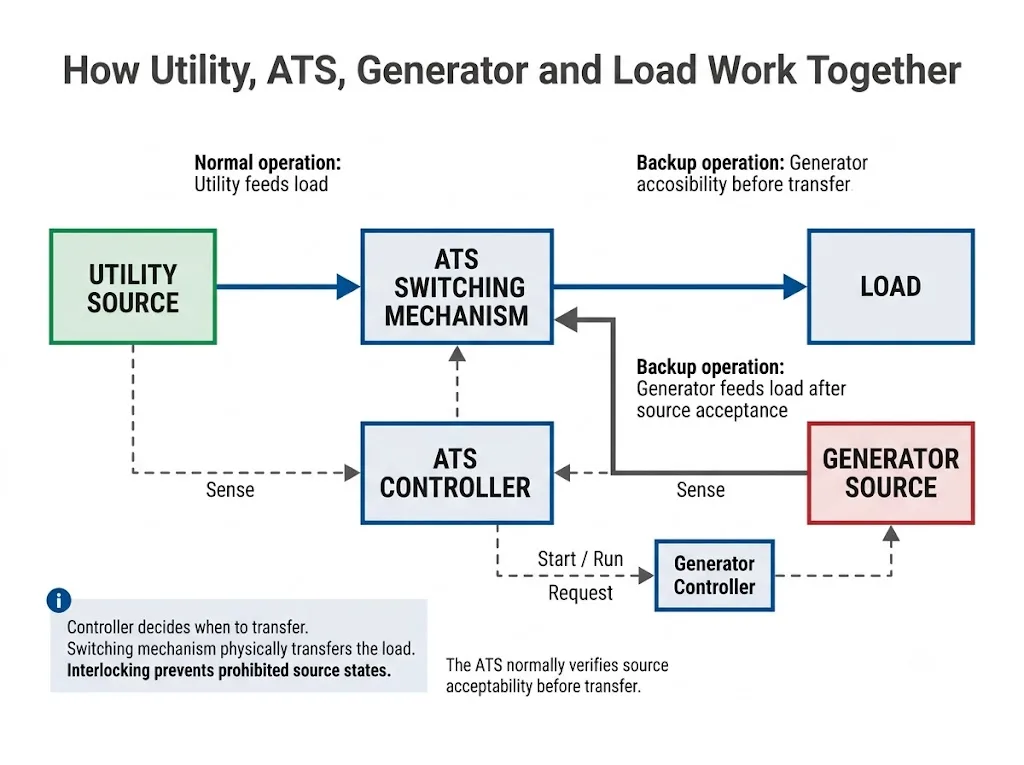
In a typical utility-to-generator system, the ATS controller does not mechanically crank the generator engine. It sends a generator start request through the intended control interface. The generator controller then carries out its own cranking, starting and voltage/frequency build-up sequence.
Cummins transfer-switch application guidance separates these events: the transfer switch initiates the start request, the engine starts and accelerates, the alternate source becomes acceptable, and only then can the transfer sequence continue according to the configured logic. [3]
Important distinction
“The ATS starts the generator” is common shorthand. For engineering and procurement, it is more accurate to say that the ATS requests generator start. This distinction matters when confirming dry contacts, remote-start inputs, auxiliary power and generator-controller compatibility.
What If the Generator Does Not Start or the Backup Source Is Not Acceptable?
Generator running does not automatically mean generator acceptable for transfer. The ATS still needs the alternate source to satisfy the source-acceptance logic required by the controller before it commands transfer. [2] [3]
If the generator fails to start, starts but does not build acceptable voltage or frequency, or becomes unstable before transfer, the ATS cannot simply assume that usable backup power is available.
The exact response can vary by equipment. Depending on the controller and system design, the ATS may remain in its present position, continue waiting, issue an alarm, record an event or follow another programmed sequence.
Buyer meaning
For critical projects, ask the supplier what happens when the alternate source fails to become acceptable. Do not assume that every ATS has the same retry, alarm or fallback behaviour.
Controller, Switching Mechanism and Interlock: Who Does What?
An ATS becomes easier to understand when the decision-making function and the physical power-switching function are separated.
| Part | Main Function | What a Buyer Should Confirm |
|---|---|---|
| ATS controller | Monitors source conditions and executes programmed transfer logic. | Sensing functions, timers, operating modes, alarms and I/O. |
| Switching mechanism | Physically carries current and changes the load connection between sources. | Rated current, utilisation/application requirements and transition mechanism. |
| Generator start interface | Passes the required start/run request to the generator control system. | Signal type and generator-controller compatibility. |
| Mechanical / electrical interlocking | In applicable designs, prevents unintended or prohibited source connection states. | How source separation and interlocking are implemented. |
Eaton describes the switching mechanism as the part that physically carries rated current and changes the load connection from one source to another. Cummins documentation also describes mechanical and electrical interlocking used to prevent inadvertent source-to-source connection in applicable transfer-switch architectures. [1] [5]
Why ATS Switching Time Is Not Total Power Restoration Time
The physical ATS switching action is only one part of the complete outage-to-restoration sequence. Before the switching mechanism can connect the load to the generator source, the system may first need to confirm the utility problem, request generator start, wait for the engine and alternator to build usable output, verify that the source is acceptable and complete any configured transfer delay. [3]
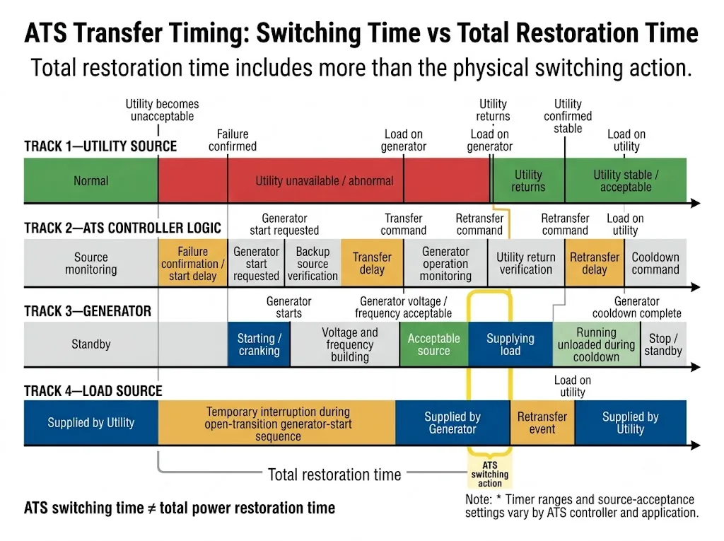
Do not specify a universal delay value.
ATS controllers provide different timing functions and adjustment ranges. Appropriate values depend on controller design, generator characteristics, load behaviour, source stability and project requirements. Manufacturer manuals provide product-specific ranges; they are not universal settings. [2] [3]
What Happens When Utility Power Returns?
The ATS normally continues monitoring the preferred source while the load is on generator power. When utility power returns, the controller evaluates whether the source has recovered to acceptable conditions before executing retransfer. [1]
Why use a return or retransfer delay?
A return delay prevents the ATS from automatically transferring the load back simply because utility voltage reappears for a moment. The delay gives the control logic time to confirm that the preferred source satisfies the required recovery conditions.
This helps reduce repeated transfer and retransfer cycles during unstable utility recovery. The exact delay range, bypass functions and return logic depend on the controller and project configuration. [2] [3]
What is generator cooldown?
After the load has returned to the preferred source, a generator-backed system may keep the engine running unloaded for a configured cooldown period before completing the stop sequence. Cummins identifies engine cooldown as a separate transfer-system timing function following retransfer. [3]
Buyer meaning
When comparing ATS controllers, ask about start delay, transfer delay, retransfer delay and engine cooldown separately. One headline “transfer time” cannot describe the complete operating sequence.
Open, Delayed and Closed Transition: What Happens During the Actual Transfer?
The transition method determines what happens electrically while the load moves from one source to the other. For buyers, this matters because motors, control systems, data equipment and other loads can respond differently to an interruption, intentional neutral period or controlled source overlap.
| Transition Type | What Happens | Buyer Meaning |
|---|---|---|
| Open transition | Source A opens before Source B closes: break before make. | The load sees an interruption during transfer. |
| Delayed transition | The load is disconnected from both sources for an intentional neutral interval before the second source is connected. | Useful where residual load voltage should decay before reconnection. |
| Closed transition | A controlled make-before-break sequence briefly overlaps suitable sources under defined conditions. | Requires suitable ATS design, source conditions and system coordination. |
Schneider Electric / ASCO describes delayed transition as a transfer sequence with an intentional off or neutral interval between sources, while ABB also identifies open, delayed and closed transition as distinct transfer methods. [4] [8]
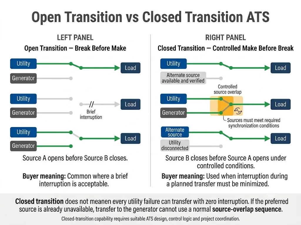
Closed transition does not mean every utility failure produces zero interruption.
If the preferred utility source has already failed, there is no live normal source available to overlap with the generator. Schneider Electric / ASCO notes that transfer from a failed normal source to emergency power is therefore an open-transition event; closed transition is applicable when both sources are available and satisfy the required conditions. [4]
Closed-transition capability is not simply a timer setting added to an ordinary switch. It requires suitable transfer equipment, control logic and system coordination. The current IEC 60947-6-1:2026 edition specifically includes requirements for ATSE having closed-transition capability. [6]
Automatic Mode vs Manual Mode
Operating-mode terminology can vary by manufacturer. Eaton, for example, distinguishes manual, non-automatic and automatic transfer arrangements. In an automatic arrangement, the controller senses source conditions and manages the transfer sequence. In other arrangements, an operator may initiate or physically perform part of the transfer process. [1]
The controller monitors source conditions and initiates transfer according to its configured logic and available functions.
A person initiates or performs transfer according to the ATS design. Generator-start and control behaviour can vary by product.
Project confirmation is required. Do not assume that putting an ATS into “manual” mode disables every automatic function. Some controller designs can retain monitoring or generator-start functions while requiring human intervention for transfer. Check the selected controller manual.
Why Buyers Should Care About the ATS Working Principle
Current rating alone does not tell you whether an ATS will behave correctly in the intended power system. Two switches with the same ampere rating can have very different sensing, timing, transition and control capabilities.
- How quickly backup power can actually become available.
- Which utility abnormalities should initiate the sequence.
- Whether the generator control interface can receive the required start command.
- Whether the load can tolerate open transition, requires a delayed neutral period, or needs another transfer method.
- Whether start, transfer, retransfer and cooldown timing can be coordinated with the project.
This is why a technical buyer should request the controller functions and sequence of operation, not only the ampere rating, pole count and quoted transfer speed.
What Should a Buyer Confirm Before Ordering an ATS?
For a useful technical review, prepare the system information that directly affects the ATS operating sequence.
- Source arrangement: utility-generator, utility-utility or another approved configuration.
- System voltage and frequency.
- Phase and neutral arrangement required by the electrical design.
- Continuous load current and relevant load characteristics.
- Generator start interface and generator-controller requirements.
- Required source-sensing functions such as voltage and frequency monitoring.
- Required transition type: open, delayed or closed transition where applicable.
- Required timing functions: start, transfer, retransfer and cooldown.
- Automatic, manual and test-mode requirements.
- Interlocking and source-separation requirements.
- Short-circuit coordination / withstand-and-closing requirements where applicable.
- Applicable standard, certification and market-access requirements.
Need to Confirm an ATS Operating Sequence?
Send the source arrangement, voltage and frequency, load type, generator interface, required transition method and timing requirements. LEEYEE can review the required operating logic against the proposed low-voltage ATS configuration.
Final selection must still be confirmed against the exact model datasheet, wiring diagram, certificate scope and project requirements.
Standards and Project Boundaries
For IEC-based low-voltage projects, the current international transfer-switch standard is IEC 60947-6-1:2026, Edition 4.0, published in April 2026. It applies to transfer switching equipment used to transfer a load between supply sources at rated voltages not exceeding 1,000 V AC or 1,500 V DC. The 2026 edition also covers automatic transfer switching equipment, stand-alone ATS controllers and ATSE having closed-transition capability. [6]
For North American applications, UL 1008 is a key standard for transfer switch equipment, including automatic transfer switches used in applicable emergency and optional standby systems. [7]
Certification scope must be checked by model.
Mentioning a standard in this guide does not mean every LEEYEE ATS model or every ATS on the market is certified to that standard. Buyers should request the certificate, listing or test documentation applicable to the exact model and destination market.
Frequently Asked Questions
Does an ATS start the generator automatically?
In a typical utility-to-generator system, the ATS controller can send a generator start request after the preferred source becomes unacceptable and the applicable start logic is satisfied. The generator controller then carries out the actual engine-start process. [3]
Why doesn't an ATS transfer immediately after utility failure?
How long does an automatic transfer switch take to transfer?
There is no universal total time. Physical contact switching can be much shorter than the complete power-restoration sequence. Generator startup, voltage and frequency stabilization, source acceptance and controller delays can all add time before the load receives backup power.
What is ATS return or retransfer delay?
It is a controller timing function used before returning the load to the preferred source after that source becomes acceptable again. It helps avoid immediate retransfer during unstable utility recovery. The required value must be confirmed for the selected controller and project.
What is the difference between open and delayed transition?
Does closed transition mean there is never a power interruption?
No. If the normal source has already failed, it cannot participate in a controlled source overlap. Schneider Electric / ASCO explains that transfer from a failed normal source to emergency power is therefore an open-transition event. Closed-transition operation is applicable when both sources are available and satisfy the required conditions. [4]
What happens if the generator does not reach acceptable voltage or frequency?
The ATS should not be assumed to transfer merely because the generator engine is running. The alternate source normally must satisfy the controller's source-acceptance conditions. The exact alarm, waiting, retry or fallback behaviour must be verified from the selected ATS controller documentation. [2] [3]
Is manual mode the same on every automatic transfer switch?
No. Manual, non-automatic, test and automatic modes can behave differently between products. Confirm which source-monitoring, generator-start and transfer functions remain active in each mode before approving the ATS for a project.
References
- Eaton, Fundamentals of Automatic Transfer Switches (ATS). Explains ATS control logic, source monitoring, operating arrangements, transfer sequence and switching mechanisms. Official source
- Eaton, Automatic Transfer Switch Controller ATC-900 Operation and Maintenance Manual, Instruction Booklet IB140012EN. Documents source-status functions including undervoltage, overvoltage, underfrequency, overfrequency, voltage unbalance, phase loss and phase reversal. Official PDF
- Cummins, Transfer Switch Application Manual. Describes source monitoring, generator start request, transfer timing, retransfer logic and engine cooldown as distinct parts of the operating sequence. Official PDF
- Schneider Electric / ASCO, technical guidance on transfer-switch transition methods and operating behaviour, including open, delayed and closed transition and the limitation of closed transition after loss of the normal source. Official source
- Cummins, B-Series CBL Bypass Isolation Transfer Switch. Manufacturer documentation describing mechanical and electrical interlocking used in that transfer-switch architecture. Official source
- International Electrotechnical Commission, IEC 60947-6-1:2026 — Low-voltage switchgear and controlgear — Part 6-1: Multiple function equipment — Transfer switching equipment, Edition 4.0. IEC official publication page
- UL Solutions, Switch Certification and Evaluation Services. Identifies UL 1008 for transfer switch equipment used in applicable emergency and optional standby systems. UL Solutions official source
- ABB, Automatic Transfer Switches Technical White Paper. Describes open, delayed and closed transition as distinct ATS transition methods and explains the role of an intentional neutral position in delayed transition. ABB official PDF
