
An automatic transfer switch in a main distribution board should be selected as part of the complete power-distribution design, not as an isolated switch. For panel builders, electrical contractors, generator integrators and project buyers, the key questions are where the transfer point is located, which loads actually require standby power, what current the ATS must carry, and how the neutral, protection and alternate source are arranged.
This guide focuses on compact automatic transfer switches used in suitable low-voltage MDB sections and essential-load distribution. It keeps the MDB engineering perspective while separating standard compact ATS applications from larger switchgear architectures that require different equipment or a project-specific solution.
Do not select the ATS from the MDB current label alone. Confirm the single-line diagram, transferred load, prospective fault conditions, upstream protection, 3P/4P requirement, neutral and earthing arrangement, generator data and the actual ratings of the selected ATS.[1][2][3]
For a compact ATS in an MDB, these are the first project inputs to confirm.
| Decision item | What to confirm | Why it matters |
|---|---|---|
| Source arrangement | Utility–generator or utility–utility | Changes source monitoring and transfer logic |
| Transferred load | Whole suitable section or selected essential loads | Defines the real current requirement |
| Design current | Actual load/design current | Must remain within the selected ATS rating and application conditions |
| Short-circuit conditions | Prospective fault current and upstream protection | Current rating alone does not prove fault suitability |
| Poles and neutral | 2P / 3P / 4P and neutral strategy | Neutral switching depends on the actual system design |
| Generator data | Voltage, frequency, capacity, neutral and start interface | The alternate source must be acceptable before transfer |
| MDB integration | Busbar, cables, enclosure, access and thermal conditions | The ATS becomes part of the complete assembly |
Procurement conclusion: select the compact ATS from the actual transfer point and load, not from the total MDB nameplate rating alone.
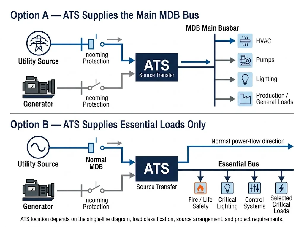
Table of Contents
Where should a compact ATS sit in an MDB?
The best location depends on which loads need an alternate source. In many projects, the useful question is not “Does the MDB need an ATS?” but “Which part of the MDB must remain supplied when the normal source fails?”
Selected MDB section
A compact ATS can supply a defined section when the transferred load and fault conditions remain within the selected device's declared ratings.
Essential-load bus
The ATS transfers only critical circuits such as selected controls, lighting, pumps or other project-defined essential loads. This can avoid sizing the standby source for every outgoing circuit.
Eaton's ATS guidance describes both utility–generator and utility–utility applications and shows why transferred loads and source availability must be defined as part of the power architecture.[4]
Utility–generator or utility–utility?
LEEYEE's compact ATS format is most naturally applied to conventional two-source transfer arrangements. The two most relevant MDB scenarios are utility–generator and utility–utility.
Utility–Generator
The ATS monitors source availability and transfers the load after the alternate source reaches acceptable operating conditions. Generator start and stop logic must be coordinated with the controller and genset interface.
Utility–Utility
There is no generator start sequence, but source priority, acceptable source conditions, transfer delay and retransfer logic still need to be defined.
How should ATS current be matched to the MDB?
The ATS current rating should match the actual transferred load, not automatically the full MDB busbar rating. If only an essential-load section is transferred, the relevant current is the load that passes through the ATS under normal and alternate-source operation.
The selected ATS must also remain within the manufacturer's declared service conditions. When the ATS is built into an MDB, the complete switchboard still has its own assembly requirements under IEC 61439 where applicable.[2][3]
Why short-circuit conditions still matter for a compact ATS
A compact size does not remove the need to check fault conditions. Rated current describes normal load carrying. Short-circuit performance addresses a different operating condition.
For an MDB application, compare the prospective short-circuit current at the ATS location and the upstream protective arrangement with the selected transfer equipment's declared data. IEC 60947-6-1:2026 is the current IEC product standard for transfer switching equipment within its stated scope.[1]
Is this a Class PC or Class CB application?
Class PC and Class CB describe different transfer-switch architectures. They should not be treated as quality levels.
LEEYEE's standard compact ATS direction is based on compact switching equipment rather than a circuit-breaker-based Class CB architecture. The exact classification and ratings of the model being quoted should still be confirmed from its technical documentation.
Class CB systems use circuit-breaker-based transfer architectures and can be appropriate in other MDB designs, but that does not mean the standard compact LEEYEE ATS should be presented as a Class CB product. Schneider Electric's current TransferPacT information shows the structural distinction between breaker-based Class CB and switch-disconnector-based Class PC arrangements.[5]
Open transition is the relevant standard configuration
For the standard compact LEEYEE ATS discussed on this page, the practical reference is conventional open-transition switching: one source is disconnected before the other source is connected.
This break-before-make behaviour is different from closed transition, where two acceptable sources are momentarily paralleled under controlled conditions. Closed-transition systems require additional equipment capabilities, source conditions and project review.[6]
A practical compact ATS selection workflow for an MDB
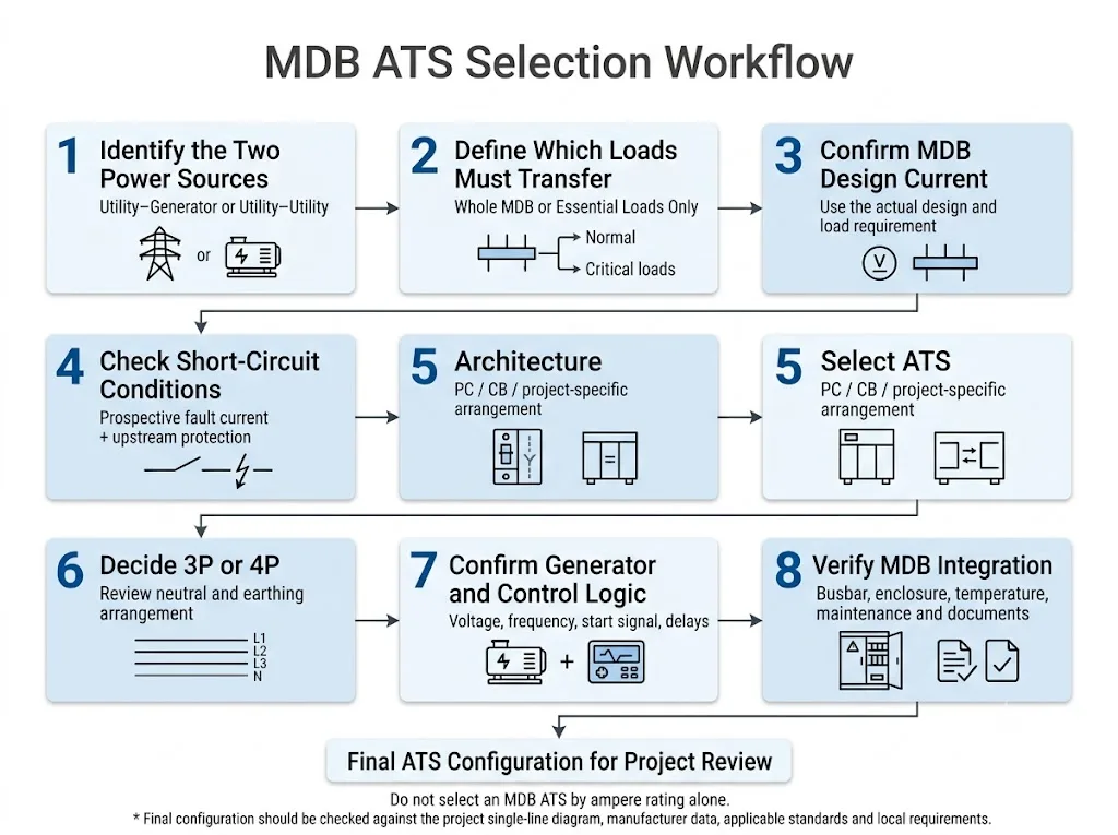
- Read the single-line diagram. Identify the normal source, alternate source and intended transfer point.
- Define which loads must transfer. Separate the actual standby load from loads that do not need alternate-source supply.
- Calculate or confirm the transferred design current. Do not automatically use the full MDB busbar rating.
- Check prospective short-circuit conditions. Compare project fault conditions and upstream protection with the selected ATS data.
- Confirm the required poles. Decide 2P, 3P or 4P from the actual system and neutral design.
- Confirm open-transition operation. If the project requires closed transition, treat it as a different engineered solution.
- Confirm generator and control requirements. Provide voltage, frequency, neutral arrangement and required start interface.
- Verify integration into the MDB. Check enclosure space, busbars, wiring, cable access, thermal conditions and maintenance access.
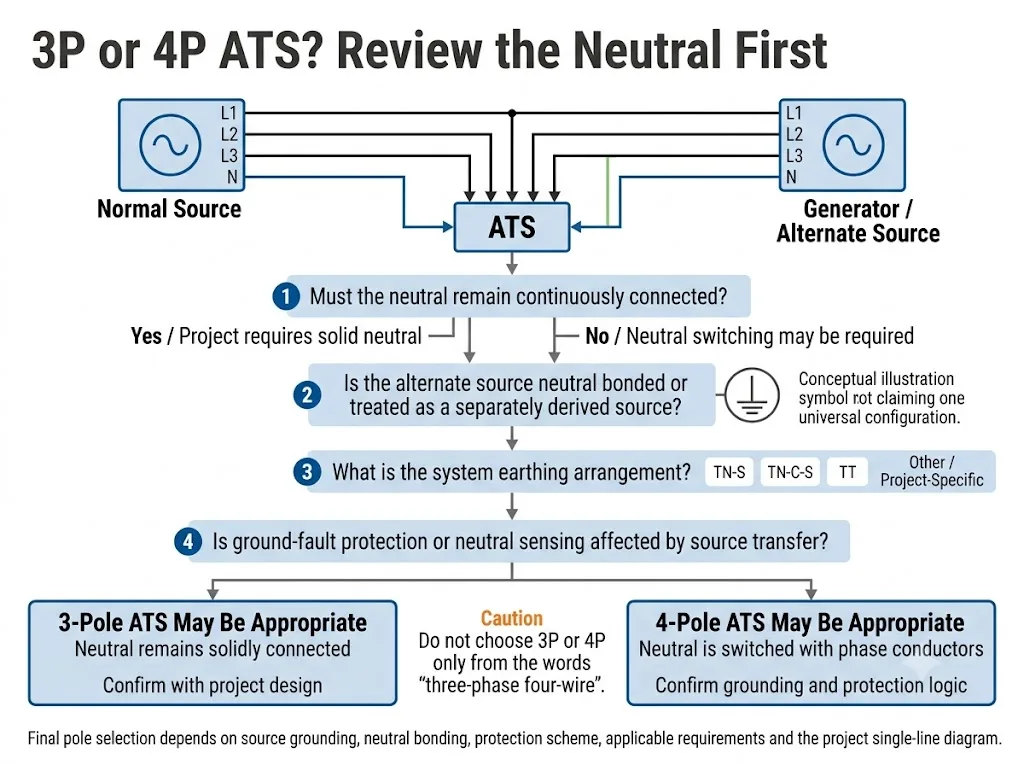
Does a three-phase four-wire MDB always need a 4-pole ATS?
No. A three-phase four-wire system does not automatically mean every project requires a switched neutral.
The decision depends on the normal and alternate source grounding arrangements, neutral bonding and any ground-fault protection or sensing affected by source transfer. Schneider Electric's ASCO guidance explains that solid-neutral versus switched-neutral selection depends on the distribution system and the grounding of the alternate source.[7]
Can a compact ATS be installed inside the MDB?
Yes, when the selected ATS is suitable for the actual current and fault conditions and the panel is designed around the device. This is one of the most relevant uses of the compact ATS format.
The ATS can be mounted as a transfer component within a suitable MDB section or an essential distribution section. The panel builder must still coordinate busbars, incoming and outgoing conductors, enclosure space, heat dissipation, wiring access and maintenance clearance.
IEC 61439-2 covers power switchgear and controlgear assemblies within its stated scope. Compliance of the ATS component does not automatically establish compliance of the finished MDB assembly.[3]
Which generator information should be confirmed?
For a generator-backed MDB section, the ATS supplier should receive enough information to confirm whether the alternate source and control interface match the selected product.
- Generator rated voltage
- Frequency
- Rated power or available current
- Neutral arrangement
- Start / stop signal requirement
- Required transfer and retransfer delays
- Critical motors or other high-inrush loads
The generator must reach acceptable operating conditions before the load is transferred. The exact voltage/frequency acceptance thresholds and delays should follow the selected controller, generator system and project requirements rather than be invented as universal values.[4]
What should you send before requesting a compact MDB ATS?
A good quotation starts with the single-line diagram and the actual transfer point. This prevents the ATS from being selected only from a current value with no information about the source, fault conditions or neutral.
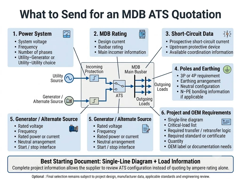
Prepare these items before fixing the ATS model
- Single-line diagram
- System voltage and frequency
- Utility–generator or utility–utility arrangement
- Actual transferred-load current
- MDB busbar rating
- Prospective short-circuit current at the ATS location
- Upstream breaker or fuse information
- 2P / 3P / 4P requirement
- Earthing arrangement
- Neutral switching requirement
- Generator voltage and frequency
- Generator rated power or available current
- Generator neutral arrangement
- Start / stop interface requirement
- Transferred-load list
- Required transfer/retransfer logic
- Required standard or certificate
- Quantity and OEM requirements
Need help confirming a compact ATS for your MDB?
Send LEEYEE your single-line diagram, transferred-load current, source arrangement, short-circuit information, pole requirement, neutral/earthing details and generator data. We can review which standard compact ATS configuration should be considered for the project.
FAQ for compact ATS selection in an MDB
Can a compact ATS be used in a main distribution board?
Yes, when the selected transfer point, load current, short-circuit conditions, poles, voltage and source arrangement are within the selected ATS's declared application limits. In many projects the compact ATS is more naturally used for a suitable MDB section or essential-load bus than for a very high-current main incomer.
Should the ATS transfer the entire MDB?
Not necessarily. If only essential loads require backup power, the ATS can be applied to a dedicated essential-load section. The project single-line diagram should define which circuits really need to transfer.
Can I select the ATS only from the MDB current rating?
No. Confirm the actual transferred load, prospective short-circuit conditions, upstream protection, poles, neutral arrangement and source information. A matching ampere number alone does not prove suitability.
Is the standard LEEYEE compact ATS a Class CB solution?
The standard compact ATS should not be presented as a circuit-breaker-based Class CB transfer architecture. Confirm the exact classification of the selected LEEYEE model from its current technical documentation before project approval.
Does the standard compact ATS use closed transition?
The standard product direction discussed on this page is conventional open-transition transfer. Closed-transition systems require a different engineered configuration and should not be assumed from the standard compact ATS.
Does a three-phase four-wire MDB always need a 4-pole ATS?
No. Pole selection depends on whether the neutral must remain connected or be switched, together with the grounding and protection arrangement of both sources.[7]
Why must short-circuit conditions be checked?
Because continuous-current rating and fault performance are different characteristics. A compact ATS should only be applied where its declared short-circuit conditions match the actual installation and associated protection.[1]
Can the compact ATS be built into an IEC 61439 MDB?
References
- International Electrotechnical Commission (IEC). IEC 60947-6-1:2026, Low-voltage switchgear and controlgear — Part 6-1: Multiple function equipment — Transfer switching equipment. IEC official publication page.
- International Electrotechnical Commission (IEC). IEC 61439-1:2020, Low-voltage switchgear and controlgear assemblies — Part 1: General rules. IEC official publication page.
- International Electrotechnical Commission (IEC). IEC 61439-2:2020, Low-voltage switchgear and controlgear assemblies — Part 2: Power switchgear and controlgear assemblies. IEC official publication page.
- Eaton. Fundamentals of Automatic Transfer Switches (ATS). Official technical guidance covering utility–generator and utility–utility applications, source monitoring and transfer sequence. Eaton technical guide.
- Schneider Electric. Source Changeover Switches / TransferPacT. Manufacturer information illustrating the distinction between breaker-based Class CB and switch-disconnector-based Class PC architectures. Schneider Electric source changeover range.
- Schneider Electric / ASCO Power Technologies. ATS Transition Modes. Technical explanation of open, delayed and closed transition operation. Schneider Electric technical FAQ.
- Schneider Electric / ASCO Power Technologies. Neutral Configurations in Transfer Switches, Document ASC-DB-NCTS, Version 1.0. Official Schneider Electric document page.
Project boundary: This page is an engineering and procurement guide for applying a compact ATS within a suitable MDB or essential distribution section. Final model selection, short-circuit coordination, pole configuration, neutral switching, generator interface, enclosure integration and compliance must be confirmed from the actual single-line diagram, current LEEYEE model data, applicable standards and local project requirements.
