
For compact low-voltage distribution panels, an automatic transfer switch is usually selected to transfer a defined load between two sources such as the utility supply and a standby generator. The key engineering questions are where the ATS should be installed, how its upstream protection is arranged, whether the neutral must switch, and whether the selected device fits the actual panel and load.
This guide is written for panel builders, electrical contractors, generator integrators and OEM buyers working with compact ATS solutions such as LEEYEE's 4-pole utility-to-generator transfer-switch configuration. It focuses on practical low-voltage distribution applications rather than large power-frame or high-current switchgear systems.
Table of Contents
Quick Answer: How Is a Compact ATS Used in a Low-Voltage Panel?
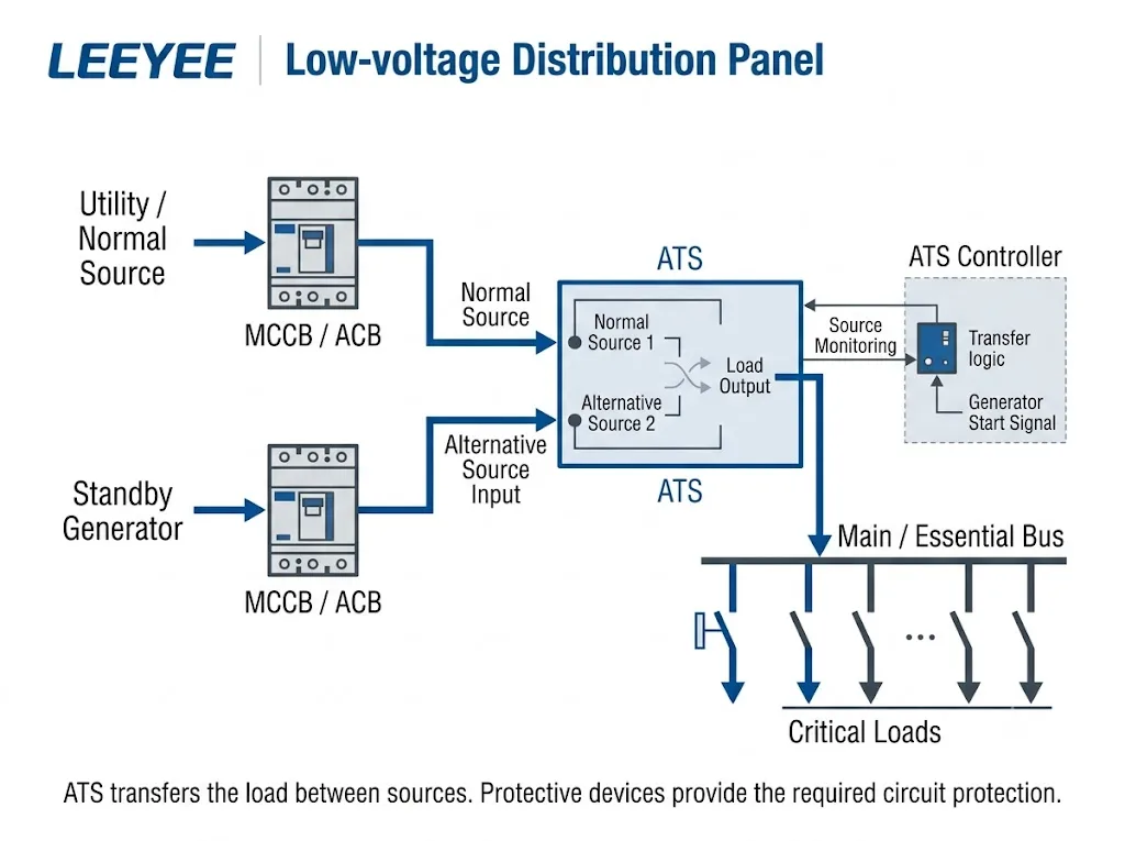
In a typical compact distribution-panel application, two power sources enter the ATS and one selected source feeds the downstream load. Source-side circuit protection is coordinated separately according to the actual electrical design. IEC 60947-6-1:2026 covers transfer switching equipment, while IEC 61439-2:2020 addresses the complete low-voltage power switchgear and controlgear assembly. [1][2]
Generator / Source B → Protective Device → ATS
ATS → Selected Distribution Loads
For a compact 4-pole ATS, the three phase conductors and neutral can be transferred between the two sources where the project requires switched-neutral operation. The exact pole strategy must still be confirmed from the project's neutral and earthing arrangement.
Buyer meaning: do not order a compact ATS only by its front-panel model marking or nominal current. Confirm the voltage, load current, source arrangement, neutral strategy, upstream protection, available fault current and panel space first.
Which Low-Voltage Panels Are Best Suited to This ATS Application?
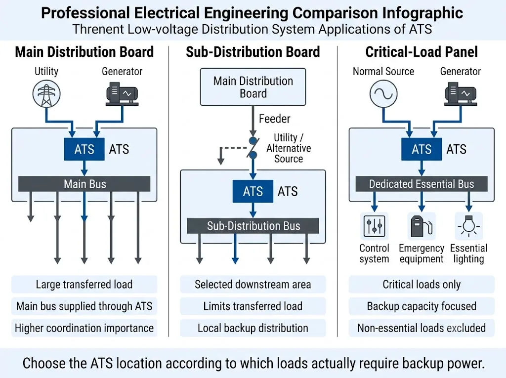
A compact ATS is most relevant where a defined low-voltage load group needs automatic or manual transfer between two available power sources.
Typical B2B applications include small and medium distribution boards, selected sub-distribution boards, generator-backed equipment panels and dedicated critical-load panels.
| Panel Application | ATS Role | Main Design Question |
|---|---|---|
| Small or medium incoming board | Transfers the selected board between two sources | Can the ATS, source protection and panel safely support the transferred load? |
| Sub-distribution board | Transfers one selected downstream area | Which feeders actually require backup power? |
| Critical-load panel | Transfers only priority loads | Can the alternative source support all transferred critical loads? |
| Generator-backed equipment panel | Changes the equipment supply between utility and generator | What transfer logic and generator-start arrangement are required? |
This guide does not assume that a compact ATS is suitable for large high-current MDB applications. Large switchboards require equipment specifically selected and documented for their current, fault level and protection architecture.
How Does the LEEYEE 4-Pole ATS Fit This Application?
Product fit: the LEEYEE product configuration shown for this application is a compact 4-pole ATS with separate A and B source terminals, load-side terminals and front Auto / Manual operation. Its visible markings also indicate grid and generator source use.
These visible features make this product format relevant to compact utility-to-generator transfer applications and other two-source low-voltage distribution arrangements. Exact current rating, operating voltage, utilization category, short-circuit capability, control functions and certification scope must be confirmed from the exact model datasheet and test documentation.
This distinction is important. The page explains how a compact LEEYEE ATS can be integrated into a low-voltage distribution panel without implying that the same product covers every large MDB, power-frame or high-current ATS application.
Should the ATS Be Installed After an MCCB, MCB or Fuse?
The ATS should not automatically be treated as the only protective device in the circuit.
IEC 60947-2:2024 covers low-voltage circuit-breakers, while IEC 60947-6-1:2026 covers transfer switching equipment. The required source-side protective arrangement must therefore be confirmed from the ATS documentation, system fault conditions and project design. [1][3]
Generator → MCCB / MCB / Fuse as Required → ATS
ATS → Distribution Loads
For compact ATS installations, upstream protection is particularly important because the transfer device must be coordinated with the available fault current and the manufacturer's declared short-circuit conditions.
Do not assume one breaker arrangement applies to every LEEYEE ATS model. The exact upstream protective-device requirement must be checked against the selected ATS documentation and project SLD.
What Does Each Device Do in a Compact ATS Panel?
| Device | Main Function | Buyer Meaning |
|---|---|---|
| ATS | Transfers the load between Source A and Source B | Confirm current, poles, source type and declared operating conditions |
| MCCB / MCB | Provides circuit protection according to its declared characteristics | Coordinate with cable, load, fault level and ATS requirements |
| Fuse | Provides overcurrent or short-circuit protection where specified | Use only where compatible with the system and ATS documentation |
| ATS control section | Supports source selection and transfer operation | Confirm actual monitoring and control functions from the exact model |
A compact ATS transfers the power source; it does not remove the need to design the circuit protection correctly.
Why a 4-Pole ATS Can Be Relevant to Utility-to-Generator Panels
A 4-pole ATS switches the three phase conductors and the neutral. This can be relevant where the system design requires the neutral to transfer between the normal and alternative sources.
Switched-neutral arrangements are commonly considered in systems involving separately derived sources, including some generator applications. Eaton technical guidance discusses switched-neutral transfer arrangements in this context. The final requirement still depends on source bonding, earthing, residual-current protection and applicable project rules. [4]
Do not interpret “generator application” as an automatic requirement for 4P. A 4-pole ATS is appropriate only when the electrical design requires the neutral to be switched.
3P or 4P: What Should the Panel Builder Confirm?
| Arrangement | Neutral Behaviour | What Must Be Confirmed |
|---|---|---|
| 3P ATS | Neutral generally remains continuous | Whether the system permits a common neutral between sources |
| 4P ATS | Neutral transfers with the phase conductors | Whether the project requires switched-neutral operation |
Pole count must follow the real conductor and earthing arrangement rather than a simple three-phase rule.
Do Not Select This ATS Only by Its Current Marking
A compact ATS may look simple, but the electrical selection still requires more than one number.
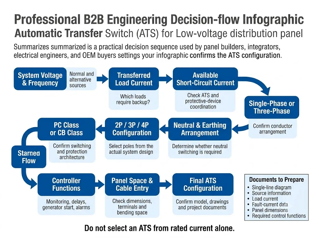
Before fixing the exact model, confirm:
- normal-source voltage and frequency;
- alternative-source voltage and frequency;
- transferred-load current;
- single-phase or three-phase arrangement;
- neutral and earthing arrangement;
- required pole count;
- available short-circuit current;
- upstream protective device;
- load characteristics and inrush current where relevant;
- required transfer and manual-control functions;
- cabinet dimensions and terminal access;
- required standards and certification documents.
Buyer meaning: a model marking such as “4P” tells you the pole configuration, but it does not by itself confirm whether the ATS is suitable for your voltage, current, fault level or protection scheme.
Why Short-Circuit Conditions Still Matter for a Compact ATS
Compact size does not remove the need for short-circuit coordination.
A fault downstream of the ATS can subject the transfer equipment to fault current until the protective device operates. The selected ATS and protective-device arrangement must therefore match the available fault conditions and the manufacturer's declared ratings. IEC 60947-6-1 and IEC 60947-2 provide the relevant equipment frameworks, while IEC 61439-2 applies to the complete panel assembly. [1][2][3]
Project confirmation: the product photograph alone does not provide enough information to determine the exact short-circuit capability of the selected LEEYEE ATS. Use the model datasheet, test documentation and specified upstream protection when approving the panel.
How Should the ATS Be Positioned Inside a Compact Panel?
Physical integration matters because compact distribution panels often have limited wiring and termination space.
Check:
- Source A terminal access;
- Source B terminal access;
- load-terminal access;
- cable bending space;
- upstream protective-device position;
- control wiring and indication access;
- manual operating access;
- maintenance clearance;
- panel temperature-rise requirements;
- complete assembly verification.
The LEEYEE compact ATS format shown for this application combines the transfer mechanism and front operating interface in one relatively compact assembly, which can simplify panel integration. Exact dimensions and installation clearances must still be taken from the selected model drawing.
What Does Auto / Manual Operation Mean for the Panel Builder?
The visible LEEYEE product configuration includes Auto / Manual operation on the front panel.
In automatic mode, source monitoring and switching behaviour depend on the internal control logic of the exact ATS model. In manual mode, the operator can use the product's intended manual operating function where permitted by the manufacturer.
Do not infer additional controller features from the product appearance. Functions such as adjustable delays, voltage thresholds, dry contacts, RS485, Modbus or remote alarms must be confirmed from the exact ATS datasheet.
What Changes in a Utility-to-Generator Application?
The product markings shown for this LEEYEE ATS make the utility/grid and generator application particularly relevant.
A typical system concept is:
Utility Unavailable → Generator Becomes Available → ATS Transfers the Load
Utility Restored → System Retransfers According to the ATS Control Logic
The exact generator-start sequence, time delays, voltage thresholds and retransfer behaviour must not be assumed from the product image. These functions require confirmation from the exact control specification.
If the connected load includes motors, pumps, transformers or other equipment with significant inrush current, generator capacity and transfer behaviour should also be reviewed before model approval.
A Practical Selection Flow for This Type of Compact ATS
- Confirm Source A: voltage, frequency and supply type.
- Confirm Source B: generator or another alternative supply.
- Define which loads transfer: entire small board or selected critical loads.
- Confirm the transferred-load current.
- Check available short-circuit current.
- Confirm upstream protection.
- Confirm whether neutral switching is required.
- Select 3P or 4P accordingly.
- Confirm the required automatic and manual functions.
- Check ATS dimensions and terminal access.
- Confirm standards, certificates and model-specific documentation.
- Approve the final panel drawing before ordering.
Common Selection Mistakes with Compact 4-Pole ATS Products
1. Assuming 4P Is Automatically Correct for Every Three-Phase Panel
Four-pole switching should be selected because the neutral needs to transfer, not simply because the system is three-phase.
2. Assuming the ATS Replaces the Upstream Breaker
The transfer function and circuit-protection function must be coordinated from the actual device documentation and electrical design.
3. Ignoring the Generator Capacity
A correctly selected ATS cannot compensate for an alternative source that is unable to support the transferred load.
4. Using the Product Model Marking as the Complete Specification
Pole count and visible model information do not replace voltage, current, short-circuit, protection and control documentation.
5. Assuming Every Compact ATS Has Remote Communication
Communication and remote-contact functions vary by model. Verify them before the panel drawing is approved.
6. Ignoring Terminal and Cable Space
Even a compact ATS requires sufficient space for two source circuits, the load circuit and safe termination access.
Important: this article explains how this type of compact ATS can be applied in a low-voltage panel. Final selection must use the exact LEEYEE model datasheet, declared ratings, wiring instructions and project electrical requirements.
Before Ordering a LEEYEE ATS for a Low-Voltage Panel
Prepare These Project Details
Need to Confirm a Compact ATS Configuration?
Send LEEYEE your single-line diagram, source voltages, transferred-load current, neutral arrangement, upstream protective device and available panel space. These details help confirm whether the selected 4-pole ATS configuration matches the actual low-voltage distribution project.
Final model approval should always be based on the exact product datasheet, declared ratings and project requirements.
Frequently Asked Questions
Is this type of compact ATS suitable for a low-voltage distribution panel?
Yes, where the panel current, voltage, source arrangement, short-circuit conditions, pole requirement and protection scheme are within the declared limits of the selected model. Suitability must be confirmed from the exact datasheet rather than from physical appearance alone.
Is a 4-pole ATS suitable for a utility-to-generator system?
It can be, particularly where the neutral must transfer between the two sources. Whether switched neutral is required depends on the project's source bonding, earthing and protection arrangement. [4]
Does the ATS need an upstream MCCB or MCB?
The required protection arrangement depends on the ATS's declared short-circuit conditions, available fault current and project design. Do not assume that the transfer switch itself replaces the required protective device. [1][3]
Can this ATS be used in a main distribution board?
It may be suitable for a small or medium incoming distribution board when the electrical ratings and fault conditions are within the selected model's declared limits. This page does not claim that the compact LEEYEE ATS is intended for large high-current power-frame MDB applications.
Does Auto / Manual mean the ATS has remote communication?
No. Auto / Manual operation does not by itself prove that the device supports RS485, Modbus, dry contacts or remote alarms. Those functions must be confirmed from the exact controller or ATS documentation.
What should I send LEEYEE before ordering?
Start with the single-line diagram, both source voltages, transferred-load current, available fault-current information, upstream protection, neutral strategy, required pole count, panel dimensions and required standards or certificates.
References
- International Electrotechnical Commission (IEC), IEC 60947-6-1:2026 — Low-voltage switchgear and controlgear — Part 6-1: Multiple function equipment — Transfer switching equipment. IEC official publication page .
- International Electrotechnical Commission (IEC), IEC 61439-2:2020 — Low-voltage switchgear and controlgear assemblies — Part 2: Power switchgear and controlgear assemblies. IEC official publication page .
- International Electrotechnical Commission (IEC), IEC 60947-2:2024 — Low-voltage switchgear and controlgear — Part 2: Circuit-breakers. IEC official publication page .
- Eaton, Fundamentals of Automatic Transfer Switches, technical guidance covering transfer-switch operation and switched-neutral applications. Eaton technical guidance .
- ABB, Automatic Transfer Switch Technical Resources, application guidance for low-voltage transfer systems. ABB ATS technical resources .
