
Wenn ein Projekt bereits ein Überspannungsschutzgerät vom Typ 1 oder Typ 1+2 erfordert,,ist die nächste Frage normalerweise, ob die Blitzimpulsstrom bewertung Iimp 12,5 kA oder 25 kA betragen sollte..Die richtige Bewertung hängt vom Blitzschutzniveau des Projekts, vom erwarteten Stromverhalten, von den Schutzarten und von der Art und Weise ab, wie der Hersteller den Wert angibt.
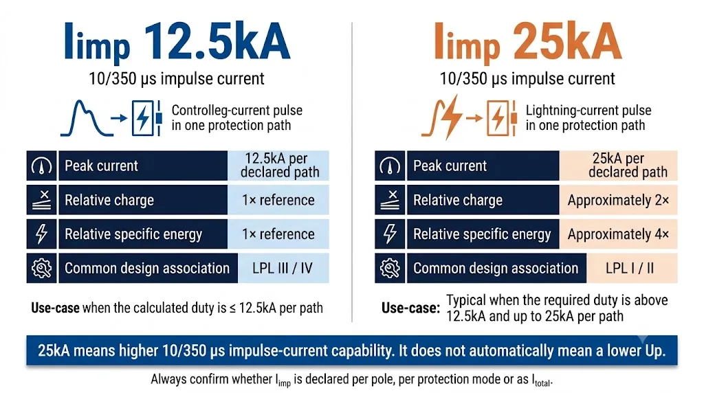
Wählen Sie Iimp 12,5kA wenn die Berechnung oder die akzeptierte Projektregel zeigt, dass die erforderliche 10/350 μs Impulsstromfähigkeit nicht mehr als 12,5 kA durch den deklarierten Pol, Ast oder Schutzmodus beträgt. Dies wird häufig mit LPL III und IV Installationen in Verbindung gebracht.
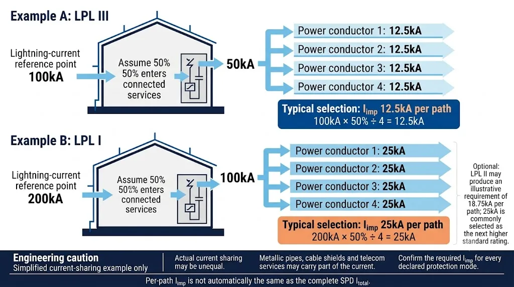
Wählen Sie Iimp 25kA wo die erforderliche Leistung über 12,5 kA und nicht mehr als 25 kA liegt. LPL I erzeugt üblicherweise einen 25 kA Bedarf in einer vereinfachten Vierpfad-Berechnung. LPL II produziert einen anschaulichen Wert von 18,75 kA, sodass die nächsthöhere gängige Produktbewertung normalerweise 25 kA beträgt.
Wählen Sie nicht aus der höchsten Zahl im Datenblatt. Bestätigen Sie, ob Iimp für einen Pol, einen Schutzmodus oder das gesamte SPD-Arrangement gilt, und überprüfen Sie Itotal separat.
Inhaltsübersicht
Iimp 12,5 kA oder 25 kA: Entscheidung in 30 Sekunden
Häufig für LPL III/IV Installationen, wenn die Stromverteilung Berechnung 12,5 kA oder weniger durch jeden deklarierten Schutzpfad unterstützt.
Häufig für LPL I und für LPL II Projekte, bei denen das anschauliche Ergebnis von 18,75 kA auf eine verfügbare 25 kA Produktbewertung aufgerundet werden muss.
Entscheiden Sie nicht allein aufgrund des Gebäudetyps oder der lokalen Blitzschlaghäufigkeit. Ermitteln Sie die LPS-Klasse, die Versorgungsanordnung und die aktuelle Verteilungsbasis.
Was ist Iimp bei einem Typ 1 SPD?
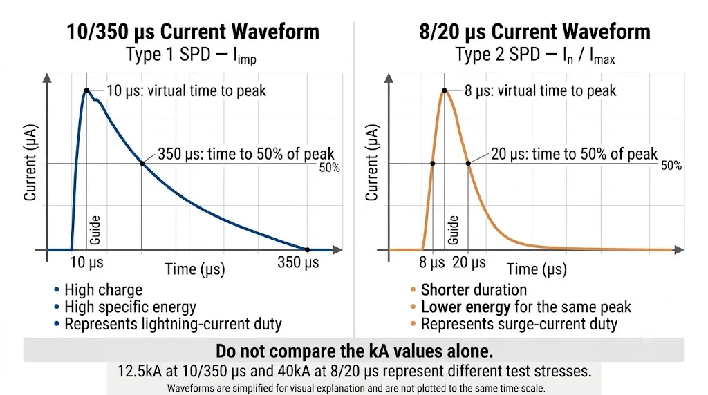
Iimp ist der Spitzenimpulsstromwert, der verwendet wird, um die Blitzstromhandhabungskapazität eines Typ 1 SPD auszudrücken. Er wird in Kiloampere angegeben und ist mit dem 10/350 μs Wellenform.
IEC 61643-11:2025 sind die aktuellen Anforderungen und Testmethodenstandards für SPDs, die an AC-Niederspannungssysteme angeschlossen sind. IEC 61643-12:2020 bietet Auswahl-, Betriebs-, Standort- und Koordinationsprinzipien. [1] [2]
Iimp darf nicht mit Unter oder Imax. Diese Werte verwenden normalerweise die kürzere 8/20 μs Wellenform, die mit der Funktion des Typs 2 verbunden ist.
Was bedeutet die Wellenform 10/350 μs?
Die Bezeichnung beschreibt einen standardisierten Stromimpuls. Die Wellenform steigt rasch bis zu ihrem Scheitelwert an und klingt danach über einen deutlich längeren Zeitraum ab als die für Typ-2-Prüfungen verwendete 8/20 μs-Wellenform.
Was ändert sich, wenn Iimp von 12.5kA auf 25kA steigt?
Wenn die standardisierte Wellenform gleich bleibt, verdoppelt eine Erhöhung des Scheitelstroms von 12.5kA auf 25kA den Spitzenstrom und etwa die Ladung. Da die spezifische Energie mit dem Integral des Stromquadrats zusammenhängt, steigt die spezifische Energiebelastung ungefähr um das Vierfache.
Iimp 12,5 kA vs. 25 kA: Hauptunterschiede
| Vergleichspunkt | Iimp 12,5kA | Iimp 25kA | Was der Käufer bestätigen sollte |
|---|---|---|---|
| Prüfwellenform | 10/350 µs | 10/350 µs | Beide Werte müssen anhand derselben Wellenform angegeben werden. |
| Spitzenstrom | 12.5kA über den angegebenen Pfad oder Modus | 25kA über den deklarierten Pfad oder Modus | Prüfen Sie genau, wo der angegebene Wert gilt. |
| Typische LPL-Zuordnung | LPL III und IV | LPL I; auch häufig für LPL II gewählt | LPL II hat einen beispielhaften berechneten Wert von 18.75kA, der normalerweise auf 25kA aufgerundet wird. |
| Impulsenergiebelastung | Unter | Etwa das Vierfache der spezifischen Energiebelastung für dieselbe Wellenform | Produkttechnologie, Größe und Nachstromverhalten können abweichen. |
| Spannungsschutzpegel Up | Produktspezifisch | Produktspezifisch | Ein höherer Iimp garantiert kein niedrigeres Up. |
| Typische Auswahlgrundlage | Erforderliche Beanspruchung nicht höher als 12.5kA | Erforderliche Beanspruchung über 12.5kA und nicht höher als 25kA | Verwenden Sie den nächsten zertifizierten Bemessungswert, der dem berechneten Bedarf entspricht oder darüber liegt. |
| Wirtschaftliche Auswirkungen | Oft kompakter und wirtschaftlicher | Oft größer oder auf einer höherenergetischen Auslegung basierend | Prüfen Sie DIN-Breite, Anschlussgröße, Vorsicherung und Platz im Schaltschrank. |
Wischen Sie horizontal, um die gesamte Tabelle anzuzeigen.
Wie das Blitzschutzniveau Iimp beeinflusst
IEC 62305 definiert Blitzschutzpegel und bildet die Grundlage für das Blitzrisikomanagement und Maßnahmen zum Überspannungsschutz. Die Ausgabe 2024 legt zudem größeren Wert auf die Dimensionierung von Stoßströmen und auf Aspekte der Stromaufteilung. [6] [7]
| Blitzschutzniveau | Referenz-Blitzstrom | Beispielrechnung mit vier Pfaden | Übliche praktische Auswahl |
|---|---|---|---|
| LPL I | 200kA | 200kA × 50% ÷ 4 = 25kA pro Pfad | Iimp 25kA |
| LPL II | 150kA | 150kA × 50% ÷ 4 = 18,75kA pro Pfad | Iimp 25kA als die nächsthöhere übliche Bemessung |
| LPL III | 100kA | 100kA × 50% ÷ 4 = 12,5kA pro Pfad | Iimp 12,5kA |
| LPL IV | Referenzklassenwert 100kA | Wird häufig auf ähnlicher Basis von 12,5kA pro Pfad bewertet | Iimp 12,5kA |
Wischen Sie horizontal, um die gesamte Tabelle anzuzeigen.
Wie man Iimp in realen Projekten auswählt
12,5kA kann geeignet sein, wenn
- Die Auslegung auf LPL III oder IV basiert.
- Die erforderliche Beanspruchung durch jeden deklarierten Schutzpfad nicht mehr als 12,5kA beträgt.
- Die Service- und Potentialausgleichsanordnung der Berechnung entspricht.
- Die genaue SPD-Topologie für das Netzsystem zertifiziert ist.
25kA kann erforderlich sein, wenn
- Die Anlage ist für LPL I oder II ausgelegt.
- Der berechnete Bedarf übersteigt 12,5 kA.
- Es stehen weniger wirksame Stromaufteilungspfade zur Verfügung.
- Der Planer, die Ausschreibung oder die nationale Vorschrift verlangt ausdrücklich 25 kA.
Benötigt jedes Gebäude mit einem externen LPS 25 kA?
Nein. Ein äußeres Blitzschutzsystem bedeutet, dass ein Typ-1-Schutz am Einspeisepunkt normalerweise zu berücksichtigen ist, legt aber nicht automatisch die Iimp-Nennleistung fest. Ein Projekt nach LPL III oder IV kann 12,5 kA verwenden, wenn die Berechnung dies stützt. LPL I oder II führt häufig zu einer Produktauswahl mit 25 kA. [4] [5]
Wie sieht es bei Standorten mit hoher Blitzaktivität und Industrieanlagen aus?
Hohe Blitzaktivität erhöht die Eintrittswahrscheinlichkeit eines Ereignisses, sie führt jedoch allein nicht zu einem festen Iimp-Wert. Industrieeinführungen, Krankenhäuser, Telekommunikationsanlagen, Gefahrenbereiche und andere kritische Einrichtungen rechtfertigen häufig die höhere Nennleistung aufgrund des LPL, des Ergebnisses der Stromverteilung oder der Folgen eines Ausfalls — nicht einfach, weil sie “industriell” sind.”
Verwechseln Sie nicht Iimp pro Pfad mit Itotal
Angebote für Typ-1-SPD führen häufig mehrere hohe kA-Werte in derselben Tabelle auf. Diese können unterschiedliche Schutzmodi beschreiben und dürfen nicht als austauschbar behandelt werden.
Iimp für einen Pfad oder Modus
Dies ist der Impulsstrom durch einen angegebenen Schutzpfad, z. B. L–N, L–PE, N–PE oder L–PEN.
Ein als “12,5 kA pro Pol” beschriebenes Produkt beweist nicht automatisch, dass jeder Schutzmodus denselben Wert hat.
Itotal für die Anordnung
Itotal ist eine separate Angabe für den vollständigen mehrpoligen SPD oder die geprüfte Anordnung.
Er muss den verifizierten Herstellerdaten entnommen werden — nicht durch Multiplikation der Anzahl der Module erzeugt werden.
Warum 3+1-Produkte besondere Aufmerksamkeit erfordern
In einem 3+1-SPD können die L–N-Schutzpfade und der N–PE-Pfad unterschiedliche Iimp-Werte aufweisen. Herstellerangaben können Iimp für L–N, Iimp für N–PE und Itotal für die vollständige Konfiguration separat angeben. [8]
Praktischer Auswahlprozess für Iimp bei Typ 1 SPD
Identifizieren Sie die äußere LPS, die Exposition gegenüber direktem Blitzstrom, die Freileitung, die Ausschreibungsspezifikation oder die lokale Vorschrift.
Bitten Sie den SPD-Lieferanten nicht, die LPL allein aus dem Gebäudenamen oder der Branche abzuleiten.
Berücksichtigen Sie die einführenden Energieleiter, verbundenen Versorgungsleitungen, Kabelschirme, das Erdungssystem und eine mögliche ungleiche Verteilung.
Bestätigen Sie, ob das System einen 1+1-, 3+1-, 4+0-, L–N-, L–PE-, N–PE- oder L–PEN-Schutz verwendet.
Verwenden Sie 12,5 kA, wenn die Anforderung nicht höher als 12,5 kA ist. Verwenden Sie 25 kA, wenn die Anforderung über 12,5 kA und nicht höher als 25 kA ist.
Überprüfen Sie Uc, Up, In, Imax, TOV-Verhalten, Kurzschlussfestigkeit, Folgestrom, Vorsicherung und Leiteranforderungen.
Bestätigen Sie, dass die genaue Spannung, Topologie, Polzahl und der Modellcode im Zertifikat oder im Geltungsbereich des verifizierten Prüfberichts aufgeführt sind.
Einkaufsliste für Typ 1+2 SPD in großen Mengen
Bei Schaltschrankprojekten, Lagerbeständen von Händlern und OEM-Bestellungen sollte die Bestellung präziser sein als nur „Typ 1+2, 25 kA“.
- Klassifizierung Typ 1 oder Typ 1+2
- Geltende IEC- oder EN-Normenausgabe
- Iimp-Wert bei 10/350 μs
- Durch Iimp abgedeckter Schutzpfad oder Modus
- Deklariertes Itotal für das vollständige SPD
- Systemspannung und Uc/MCOV
- Spannungsschutzpegel Up
- In und Imax bei 8/20 μs
- TN-C-, TN-S-, TN-C-S-, TT- oder IT-System
- 1+1-, 3+1-, 4+0- oder andere Topologie
- L-N-, L-PE-, N-PE- und L-PEN-Nennwerte
- Netzfolgestrom-Löschfähigkeit
- Kurzschlussfestigkeit oder -beständigkeit
- Maximal zulässige Vorsicherung
- TOV-Verhalten und sicherer Ausfallmodus
- Anschlussgröße und Anzugsdrehmoment
- Steckbare oder Monoblock-Bauweise
- Optische Anzeige und Fernmeldekontakt
- Genaue Modellabdeckung in der Zertifizierung
- OEM-Etikett, Verpackung, Mindestbestellmenge (MOQ) und Vorlaufzeit
Parameter, die eine gesonderte Bestätigung erfordern
Iimp ersetzt nicht Auswahl von Uc, Auswahl von Up, Nennstrom oder Auswahl von Imax. Jeder Parameter beantwortet eine andere technische Frage.
| Parameter | Was der Lieferant angeben sollte | Warnhinweis |
|---|---|---|
| Iimp | Wert, 10/350 μs-Wellenform und genauer Schutzmodus | Nur „25kA SPD“ ohne Wellenform oder Modus |
| Itotal | Verifizierter Wert für die vollständige Konfiguration | Summe durch informelle Multiplikation erstellt |
| Typendeklaration | Typ 1 oder Typ 1+2 gemäß geltender Norm | „T1+T2“ nur als Marketingtext verwendet |
| Zertifikat | Zertifikatsinhaber, exakte Modellfamilie und Parameterumfang | Zertifikat gehört zu einem anderen Modell oder Hersteller |
| Netzwerksystem | Zugelassene Topologie für TN-, TT- oder IT-Systeme | Die gleiche Konfiguration wird für jedes System angeboten |
| Sicherungsschutz | Maximale Absicherung oder Schutzschalter und Koordinationsbedingungen | Keine deklarierte Anforderung an den Vorsicherungsschutz |
| Nach oben | Deklariertes Up für die relevanten Modi | Ein höherer Iimp wird als Nachweis für ein niedrigeres Up präsentiert |
| OEM-Zulassung | Genehmigtes Modell, technisches Etikett, Verpackung und Dokumente | Produktion beginnt vor technischer Bestätigung |
Wischen Sie horizontal, um die gesamte Tabelle anzuzeigen.
Angebotsanfrage-Vorlage kopieren und versenden
Senden Sie die folgenden Informationen an den SPD-Hersteller, um wiederholte Klärungen und fehlerhafte Angebote zu reduzieren.
Häufig gestellte Fragen
Ist ein 25kA Typ 1 SPD immer besser als ein 12,5kA Modell?
Er verfügt zwar über eine höhere Impulsstrombelastbarkeit (10/350 μs), ist aber nicht automatisch die bessere Gesamtspezifikation. Uc, Up, Topologie, Kurzschlussbedingungen, Vorsicherungsschutz und Zertifizierung müssen ebenfalls zum Projekt passen.
Kann ein 25kA SPD einen 12,5kA SPD ersetzen?
Er bietet möglicherweise ausreichend Iimp-Spielraum, jedoch nur, wenn auch die Spannungsfestigkeit, das Netzwerksystem, die Schutzmodi, Up, die Folgestromlöschfähigkeit, der Vorsicherungsschutz, die Anschlüsse und die Zertifizierung geeignet sind.
Warum wird LPL II normalerweise mit einem 25kA SPD kombiniert?
Eine vereinfachte Vier-Pfad-Berechnung ergibt 18,75 kA pro Pfad. Da 18,75 kA kein üblicher Produktnennwert ist, liegt der nächsthöhere handelsübliche Wert normalerweise bei 25 kA.
Erfordert ein externes Blitzschutzsystem immer 25 kA?
Nein. Bei Projekten der LPL III oder IV können 12,5 kA verwendet werden, sofern dies durch die Auslegung der Stromverteilung gestützt wird. LPL I oder II führt üblicherweise zur Auswahl von 25 kA.
Ist Iimp 12,5 kA dasselbe wie Imax 12,5 kA?
Nein. Iimp verwendet eine 10/350 μs Wellenform für die Typ 1-Belastung. Imax verwendet eine 8/20 μs Wellenform für die Typ 2-Belastung. Die Strombelastungen sind unterschiedlich.
Kann ich den Strom pro Pol mit der Anzahl der Pole multiplizieren?
Nicht, es sei denn, der Hersteller deklariert den resultierenden Wert als Itotal für die geprüfte Gesamkonfiguration.
Was sollte bei einem 3+1 Typ 1+2 SPD überprüft werden?
Überprüfen Sie Iimp für die L–N-Pfade, Iimp für den N–PE-Pfad, Itotal, Uc, Up, das Folgestromverhalten, den Vorsicherungsschutz und die Kompatibilität mit dem TT- oder TN-S-System.
Was passiert, wenn der erforderliche Iimp 25 kA überschreitet?
Überprüfen Sie eine dedizierte Typ 1-Lösung mit höherer Nennleistung sowie die gesamte Blitzschutzarchitektur. Verwenden Sie ein 25-kA-Produkt nicht über dessen deklarierte und zertifizierte Belastung hinaus.
Brauchen Sie eine SPD-Spezifikation vom Typ 1+2 für eine OEM-Bestellung?
Senden Sie uns die Systemspannung, Erdungskonfiguration, Topologie, LPL, erforderliche Iimp, Up, Kurzschlussbedingungen und den Zielmarkt. LEEYEE kann die Bestellparameter vor der Angebotserstellung und Kennzeichnungsfreigabe überprüfen.
Technische Referenzen
- IEC 61643-11:2025, Überspannungsschutzgeräte für Niederspannung – Anforderungen und Prüfungen für Überspannungsschutzgeräte in Niederspannungsanlagen. IEC-Publikation anzeigen
- IEC 61643-12:2020, Auswahl- und Anwendungsgrundsätze für Überspannungsschutzgeräte in Niederspannungsanlagen. IEC-Publikation anzeigen
- Handbuch der elektrischen Installation, Auswahl eines Typ 1 SPD, einschließlich des häufig referenzierten Mindest-Iimp von 12,5 kA bei 10/350 μs pro Zweig, sofern keine strengere Regel gilt. Auswahlhilfe ansehen
- Phoenix Contact, Typ 1+2 Überspannungsschutz-Portfolio und Anwendungsleitfaden für 12,5 kA und 25 kA Nennleistungen. Technische Referenz ansehen
- Legrand, technische Dokumentation für modulare SPD, einschließlich 12,5 kA-pro-Pol-Richtlinien für LPL III/IV-Anwendungen. Technisches Dokument ansehen
- IEC 62305-1:2024, Blitzschutz – Allgemeine Grundsätze und Blitzstromparameter. IEC-Publikation anzeigen
- IEC 62305-4:2024, Überspannungsschutzmaßnahmen für elektrische und elektronische Systeme, einschließlich Überlegungen zur Stromaufteilung. IEC-Publikation anzeigen
- Herstellerdaten von DEHNshield mit separaten Iimp-Werten für L–N- und N–PE-Modi sowie einer separaten Angabe zum Itotal. Technische Produktdaten ansehen
Nationale Installationsvorschriften, Projektspezifikationen und die Berechnungen des verantwortlichen Blitzschutz-Ingenieurs haben Vorrang vor allgemeinen Auswahlbeispielen. Überprüfen Sie die neuesten Produktdaten und den Zertifizierungsumfang vor der Bestellung.
