
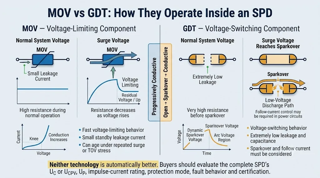
MOV und GDT werden beide zum Überspannungsschutz verwendet, aber sie funktionieren unterschiedlich. Ein MOV limitiert die Spannung progressiv. Ein GDT oder Funkenstrecke bleibt hochwiderständig, bis der Funkenüberschlag einen leitfähigen Entladungspfad schafft.
Für die Beschaffung von Engineering und OEM ist die eigentliche Frage nicht einfach, welches Bauteil besser ist. Der Käufer muss bestimmen, welche komplette SPD-Struktur zur Anwendung, Systemspannung, Schutzmodus, Überspannungswelle, Fehlerbedingungen und Zertifizierungsanforderungen passt.
Inhaltsübersicht
Schnelle Antwort: Was ist der Unterschied zwischen MOV und GDT?
MOVs sind spannungsbegrenzende Komponenten. Ihr Widerstand verringert sich fortschreitend, während die Spannung ansteigt. Sie werden häufig in AC Typ 2 SPDs, PV DC SPDs und anderen Stromschutzschaltungen eingesetzt, da sie ein kompaktes und vorhersehbares spannungsbegrenzendes Verhalten bieten.
GDTs und Leistung-Funkenstrecken sind spannungswechselnde Komponenten. Sie bleiben während des normalen Betriebs hochresistiv und wechseln in einen leitenden Entladezustand, nachdem es zum Überschlag gekommen ist. Sie sind nützlich, wenn sehr niedrige Leckströme, niedrige Kapazitäten oder hohe Isolationswerte im normalen Zustand erforderlich sind.
Keine der Technologien ist automatisch besser. Vergleichen Sie die Uc oder Ucpv, Up, Iimp, In, Imax, Schutzmodus, Nachlaufverhalten, Trennstruktur, Kurzschlussschutz und Zertifizierung der kompletten SPD. [1] [8]
MOV vs GDT: Die wesentlichen Unterschiede
Die folgende Tabelle gibt die direkte Antwort, die die meisten Ingenieure vor der Überprüfung der tiefergehenden technischen Abschnitte benötigen.
Wischen Sie horizontal, um die vollständige Vergleichstabelle zu sehen.
| Vergleichspunkt | MOV | GDT / Funkenstreckentechnologie | Käuferinterpretation |
|---|---|---|---|
| Betriebsprinzip | Spannungsbegrenzender nichtlinearer Widerstand | Spannungsschaltung nach Überschlag | Die beiden Technologien steuern transiente Spannung auf unterschiedliche Weise. |
| Leckstrom im Normalbetrieb | Ein kleiner Leckstrom ist normalerweise vorhanden | Extrem niedriger Leckstrom vor dem Überschlag | Leckage und Isolierung können in N-PE-, Signal- und Überwachungsanwendungen von Bedeutung sein. |
| Spannungsverhalten | Die Spannung folgt der nichtlinearen Strom-Spannungs-Kurve des MOV | Die Spannung steigt auf dynamisches Durchschlagen und fällt dann in den Bogenbereich | Vergleichen Sie die getesteten Up des vollständigen SPD, nicht nur die Komponentenbeschreibung. |
| Reaktionsverhalten | Schnelle Materialreaktion, aber Verkabelung und Induktivität beeinflussen weiterhin das Ergebnis | Das Durchschlagen hängt von der Spannungsanstiegsrate und der Gerätearchitektur ab | Generische Nanosekundenansprüche ersetzen keine vollständigen SPD-Testdaten. |
| Surge-Strombehandlung | Kann hoch sein, wenn sie richtig dimensioniert, verbunden und thermisch geschützt sind | Kann sehr hoch sein nach der Zündung in einem entsprechend gestalteten Gerät | Vergleichen Sie immer die Wellenform, den Strom pro Pol und die Testklassifikation. |
| Kapazität | Allgemein höher | Allgemein sehr niedrig | GDT-Technologie ist oft nützlich in Hochfrequenz- und Signalschutz. |
| Alterung | Wiederholte Überspannungen, Wärme und TOV können Leckströme und Varistor-Eigenschaften verändern | Harsh discharge duty kann Elektroden erodieren oder das Durchschlagverhalten verändern | Keine der Komponentenfamilien sollte als unendlich haltbar beschrieben werden. |
| Strom verfolgen | Erzeugt nicht das gleiche Lichtbogen-Nachlaufstromproblem wie ein Funkenstrecke | Der Strom der Stromquelle kann nach der Zündung weiterlaufen, es sei denn, das Design löscht oder kontrolliert ihn | Die Nachlaufstrom-Leistung ist in der Stromversorgung und einigen DC-Anwendungen entscheidend. |
| Häufige Anwendungen | AC Typ 2, PV DC und spannungsbegrenzende Schutzvorrichtung für den Stromanschluss | N-PE-Module, primäre Signalstufen und viele Typ 1 Blitzstromanwendungen | Dies sind gängige Verwendungen, keine universellen Regeln. |
| Hauptbeschaffungsrisiko | Ignorieren von TOV, thermischer Trennung und Verhalten am Lebensende | Ignorieren von dynamischem Durchschlag, Vorlaufspannung und Nachlaufstrom | Genehmigen Sie die vollständige SPD, nicht nur die interne Komponente. |
Welche Struktur wird häufig in jeder SPD-Anwendung verwendet?
Wischen Sie horizontal, um die vollständige Anwendungstabelle anzuzeigen.
| Anmeldung | Verbreitete Struktur | Hauptgrund | Was zu bestätigen ist |
|---|---|---|---|
| AC Typ 2 Verteilungstafel SPD | Häufig auf MOV basierend | Kompakte spannungsbegrenzende Schutzvorrichtung | Uc, In, Imax, Up, thermische Trennung und Backup-Gerät |
| TT 1+1 oder 3+1 N-PE Pfad | Häufig auf Funkenstrecken basierend | Hohe N-PE-Isolation und sehr niedrige normale Leckage | N-PE Gesammtstrom, Systemtopologie, Uc und Up |
| Typ 1 Serviceeingang | Getestete Funkenstrecke, MOV oder koordinierte Typ-1-Struktur | Muss dem angegebenen Blitzimpuls standhalten | Iimp, 10/350 μs-Wellenform, Up und Nachlaufverhalten |
| PV-DC-Überspannungsschutzgerät | PV-spezifische spannungsbegrenzende Strukturen sind häufig | Spannungsbegrenzung mit sicherer DC-Fehlertrennung | Ucpv, Iscpv, In, Imax oder Iimp, Up und Zertifikatsumfang |
| RS485 oder Signal-SPD | GDT plus koordinierter Feinschutz ist häufig | Niedrige Kapazität mit einer niedrigeren endgültigen Restspannung | Signalspannung, Kapazität, Frequenz, Up und Prüfklasse |
| Niedrigleckende hybride Schutzvorrichtung | Die Struktur der Serie GDT- und MOV-Elemente kann verwendet werden | Der GDT kann das MOV von der kontinuierlichen Betriebsspannung isolieren | MCOV, vordere Schutzspannung, Klemmverhalten und Prüfung |
LEEYEE OEM-Bewertungsschwerpunkt
Für die Projektabstimmung sollte die Überprüfung mit der Systemspannung, der Erdungsanordnung, dem Schutzmodus und der anwendbaren SPD-Klassifizierung beginnen. Interne MOV-, GDT- oder Funkenstrecken-Technologie werden dann zusammen mit Up, Stromstoßwellenform, Fehlverhalten, Trennung, Produktetikett und Umfang des Zertifikats bewertet.
Wie funktioniert ein MOV in einem Überspannungsschutzgerät?
MOV: Spannungsbegrenzendes Verhalten
MOV steht für Metall-Oxid-Varistor. Sein Widerstand ändert sich nichtlinear mit der angelegten Spannung. Bei normaler Systemspannung bleibt die Baugruppe bei hohem Widerstand und führt einen kleinen Leckstrom.
Ein nackter MOV ist kein vollständiges SPD.
Ein praktisches Leistungs-SPD hängt auch von der thermischen Trennung, der internen Leiteranordnung, der Isolierung, der Statusanzeige, den Anschlüssen, der Gehäusekonstruktion und der Koordination mit integrierter oder externer Sicherung ab.
Wiederholte Überspannungsbelastung, übermäßige Betriebsspannung, Wärme oder TOV können die MOV-Leckage und Temperatur erhöhen. Eine sichere Trennung und eine klare Lebensdaueranzeige sind daher wichtige Teile des vollständigen Designs. [10]
Die Anzahl oder der Durchmesser der MOV-Scheiben beweisen nicht die vollständige SPD Leistung. Die Materialzusammensetzung, die Anschlussmethode, die thermische Regelung, die Abmessungen der Leiter und die Tests des Gesamtprodukts beeinflussen alle das Ergebnis.
Wie funktioniert ein GDT oder Funkenstrecke in einem SPD?
GDT: Spannungsschaltverhalten
Ein Gasentladungsrohr enthält zwei oder drei Elektroden in einem abgeschlossenen Gehäuse mit einer kontrollierten Gasgemisch. Bei normaler Spannung ist der Abstand nicht leitend und bietet einen sehr hohen Isolationswiderstand. Wenn der transiente Zustand seine dynamische Durchschlagbedingung erreicht, ionisiert das Gas und erzeugt einen leitfähigen Entladungsweg.
Die Frage der Nachstrom
Sobald ein Leistungsfunkenbogen gezündet hat, kann die angeschlossene Quelle weiterhin Strom durch den leitfähigen Weg liefern, nachdem der ursprüngliche transienten Zustand vergangen ist. Dies ist als Nachstrom bekannt.
Das komplette Leistungs-SPD muss diesen Strom löschen, unterbrechen oder sicher koordinieren. Eine hohe Impulsstromfähigkeit allein beweist nicht die Eignung für jede AC- oder DC-Quelle.
IEC 61643-312 definiert die Eigenschaften und Anwendungen von GDT Komponenten und unterscheidet diese Komponenten speziell von den vollständigen Anforderungen eines fertigen SPD. [7]
Ist ein GDT dasselbe wie jede Hochspannungsfunkenstrecke?
Nein. Ein GDT ist eine Art von gasgefülltem Spannungsschalter-Komponente, aber der Begriff Funkenbogen umfasst ein breiteres Spektrum von Strukturen.
- Ein diskreter GDT ist normalerweise eine kompakte, geschlossene Komponente mit zwei oder drei Elektroden.
- Ein Leistungs-SPD kann größere eingekapselte, ausgelöste, Kohlenstoff-, Graphit- oder Mehr-Elektroden-Funkenbogenstrukturen verwenden.
- Typ-1-Funkenbogenmodule können spezielle Lichtbogenkammern, Auslösungssysteme und nachstromlöschende Strukturen enthalten.
Statt nur zu fragen, ob ein SPD einen GDT enthält, fragen Sie, ob der Schutzweg spannungsbegrenzend oder spannungsschaltend ist, welche Impulswelle anwendbar ist, welches Nachstromverhalten erklärt wird und wie das vollständige SPD getestet wurde.
Reaktionszeit, dynamische Funkenüberschlag und Spannungs-Schutzlevel
Viele Komponentenvergleiche behaupten, dass ein MOV schneller und ein GDT langsamer ist. Diese Aussage ist zu einfach für eine vollständige SPD-Auswahl.
Die dynamische Funkenüberschlagspannung eines GDT hängt teilweise von der Spannungsanstiegsgeschwindigkeit ab. Ein steiler Transient kann eine kurze Vorderspannung erzeugen, bevor der leitende Entladezustand etabliert wird. Serien-GDT-und-MOV-Strukturen können daher eine Vorder-Schutzspannung aufweisen, die bei der Koordination berücksichtigt werden muss. [11]
Das Verhalten von MOV wird auch durch die Anschlusslänge, die induktive Eigenschaften des internen Leiters, die Stromamplitude und die Prüfspannung beeinflusst. Die am Gerät auftretende Spannung ist das Ergebnis der kompletten SPD und der Installation, nicht einer generischen Komponentenantwortzeit.
Verwenden Sie das angegebene Spannungs-Schutzniveau Up, die geltende Impulswellenform, den Schutzmodus und die Installationsanforderungen. Genehmigen Sie eine SPD nicht nur aufgrund eines beworbenen Nanosekundenwerts.
Warum verwenden viele N-PE-Module Funkenstreckentechnologie?
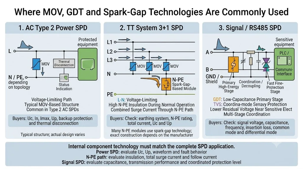
In TT-Systemen und einigen TN-S-Anordnungen werden häufig 1+1- oder 3+1-Topologien verwendet. Phasenleiter sind über spannungsbegrenzende Pfade gegen Neutralleiter geschützt, während der Neutralleiter über ein spannungsschaltendes N-PE-Modul mit dem Schutzerd verbunden ist.
Typische 1+1-Anordnung
- L-N: üblicherweise ein MOV-basierter spannungsbegrenzender Pfad
- N-PE: üblicherweise ein funkenbasierter Schaltweg
- Verwendet in geeigneten einphasigen TT- und TN-S-Anwendungen
Typische 3+1 Anordnung
- L1/L2/L3-N: häufig MOV-basierte Schutzwege
- N-PE: ein hochkapazitiver spannungsschaltender Schutzweg
- Verwendet in geeigneten dreiphasigen TT- und TN-S-Anwendungen
Der N-PE-Schaltweg bietet während des normalen Betriebs eine hohe Isolation und sehr geringe Leckströme. Bei einem Überschlag trägt er den kombinierten Impulsstrom vom Neutralleiter zum Schutzerdungssystem. [14]
Bestätigen Sie, ob der angegebene Wert der Gesamtstrom, der Strom pro Schutzmodus oder der Strom pro Pol ist. Produkte mit ähnlichen 1+1 oder 3+1 Beschriftungen können unterschiedliche N-PE Entladekapazitäten haben.
Wie sich MOV- und GDT-Strukturen nach SPD-Anwendung unterscheiden
Verteilerkästen und Steuerpanels
MOV-basierte Strukturen sind in Typ 2 AC SPD häufig, da sie kompakten spannungsbegrenzenden Schutz für Verteilungs-Level Überspannungsströme bieten.
- Bestätigen Sie Uc, In, Imax und Up.
- Überprüfen Sie die thermische Trennung und den Backup-Schutz.
- Passen Sie den Schutzmodus an das Erdungssystem an.
Blitzstrom-Eintrittspunkte
Produkte der Typ 1 können speziell entwickelte Funkenstrecken, MOV-Baugruppen oder koordinierte Strukturen verwenden. Die Klassifizierung Typ 1 basiert auf Tests des Gesamtprodukts, nicht auf dem Komponentenname.
- Überprüfen Sie Iimp mit der 10/350 μs Wellenform.
- Bestätigen Sie Up und den Strom pro Pol.
- Überprüfen Sie den Nachlaufstrom und die downstream Koordination.
Kombinatorboxen und Solarinverter
Spannungsbegrenzer-Varistorstrukturen sind in PV-DC-SPDs häufig anzutreffen, aber die wichtige Frage ist, ob das gesamte Gerät unter DC-Überlast- und Fehlerbedingungen sicher getrennt werden kann.
- Bestätigen Sie Ucpv, Iscpv, In, Imax oder Iimp und Up.
- Überprüfen Sie die Polarität und das PV-spezifische Fehlverhalten.
- Überprüfen Sie den Zertifikatsumfang im Vergleich zum bestellten Modell.
RS485, Telekommunikations- und PLC-Schnittstellen
GDTs werden oft als niedrigkapazitive Hochenergie-Hauptstufe verwendet. Eine koordinierte TVS oder eine andere feine Schutzstufe kann dann die verbleibende Spannung in der Nähe empfindlicher Elektronik begrenzen.
- Bestätigen Sie die Signalspannung und die maximale Betriebsspannung.
- Überprüfen Sie die Kapazität, Frequenz und Einfügedämpfung.
- Überprüfen Sie den Schutz gegen Gleichtakt- und Gegentaktstörungen.
AC-Leistung, PV-DC und Telekommunikations- oder Signal-SPDs unterliegen unterschiedlichen Produktanforderungen. Ein komponentenbezogener Vergleich kann daher die anwendungsspezifische Auswahl von Komplettprodukten nicht ersetzen. [2] [4] [6]
Warum werden MOV und GDT manchmal kombiniert?
MOV- und GDT-Technologien können in Reihe geschaltet oder in einem mehrstufigen Schaltkreis koordiniert werden. Ziel ist es, nützliche Eigenschaften zu kombinieren, nicht einfach nur ihre Stromwerte zusammenzuzählen.
Serie GDT-und-MOV-Schutz
In einem seriellen Hybrid kann der GDT den MOV während des normalen Betriebs von der kontinuierlichen Systemspannung isolieren. Dies kann den Standby-Leckstrom durch den MOV verringern und den kontinuierlichen elektrischen Stress reduzieren. Nach einem Durchschlag trägt der MOV zur Spannungsbegrenzung bei. [12] [13]
Koordinierter Signalschutz
Ein GDT kann den höheren Energiezufluss aufnehmen, während ein nachgeschalteter Suppressor die verbleibende Transienz in der Nähe der geschützten Schnittstelle begrenzt. Ein Koordinierungselement kann erforderlich sein, damit die Hauptstufe arbeitet, bevor die Feinschutzstufe überlastet wird.
Überprüfen Sie MCOV oder Betriebsspannung, Frontschutzspannung, Klemmverhalten, Leckstrom, Stromwellenform und Komplettproduktprüfung. Falsch koordinierte Komponenten können dennoch schlechten Schutz bieten.
MOV vs GDT Alterung, Ausfall und Sicherheit
MOV-Stress und Lebensende
Wiederholte Impulse, hohe Umgebungstemperaturen, übermäßige Dauerbetriebsspannung und TOV können die Eigenschaften von MOV ändern. Leckage und Selbstheizung können zunehmen, was thermische Trennung und Statusanzeige wichtig macht.
GDT- und Funkenlückenverschleiß
Eine schwere Entladepflicht kann Elektroden erodieren oder die Durchschlagseigenschaften verändern. Leistungsentladungskonstruktionen müssen auch den Lichtbogen ausschalten, den Strom und die Isolierung nach dem Betrieb kontrollieren.
Die Sicherheit des Fertigprodukts hängt auch von internen Trennschaltern, Backup-Schutz, Isolationsabständen, Anschlüssen, Gehäusematerial, Anzeige-Systemen und Kurzschlusssicheren ab.
Ein Zertifikat für eine MOV-, GDT- oder thermische Schutzkomponente beweist nicht, dass der montierte SPD auf DIN-Schiene den geltenden Gesamtproduktstandard erfüllt.
OEM- und Ingenieureinkaufscheckliste
Beginnen Sie eine RFQ nicht nur mit “MOV SPD” oder “GDT SPD.” Beginnen Sie mit dem System und der erforderlichen Schutzleistung.
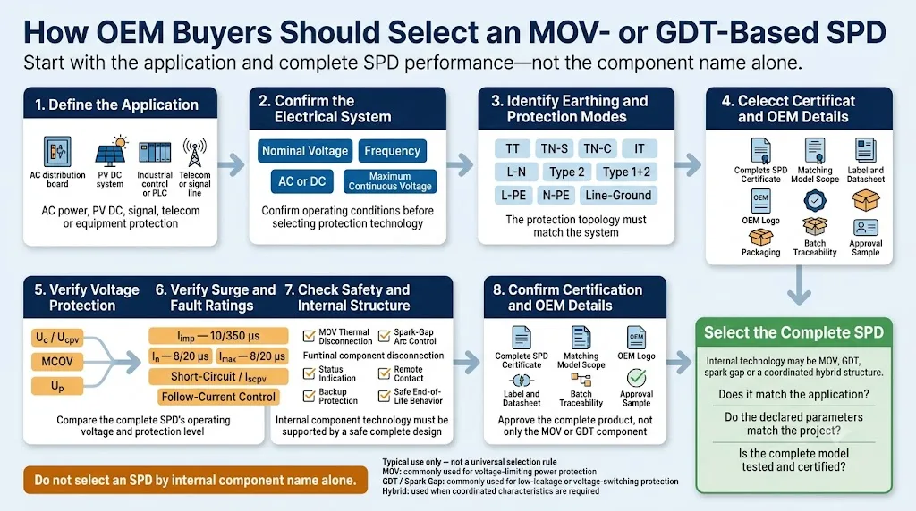
- Anwendung: AC-Verteilung, PV-DC, Telekommunikation, Industriesignal, Steuerungspanel oder Geräteschutz.
- Systemspannung: Nennspannung, maximale Dauerbetriebsspannung und Frequenz, sofern zutreffend.
- Erdungssystem: TT, TN-S, TN-C, IT, schwimmendes DC oder geerdetes DC.
- SPD-Kategorie: Typ 1, Typ 2, Typ 1+2, Typ 3, PV SPD oder Signal SPD.
- Schutzmodus: L-N, L-PE, N-PE, L-L, positiv-negativ oder Leiter-Erde.
- Spannungswerte: Uc, Ucpv, MCOV und deklarierter Up.
- Stromwerte: Iimp, In und Imax mit der anwendbaren 10/350 μs oder 8/20 μs Wellenform.
- Fehlverhalten: Kurzschlussfestigkeit, Iscpv, Nachlaufstromsteuerung und Sicherungs-Schutzgerät.
- Sicherheitsstruktur: thermische Trennung, Lichtbogenkontrolle, Isolierung, Anzeige und Fernkontakt.
- Zertifizierung: vollständiger Modellprüfbericht, Zertifikat Umfang, Standardausgabe und passendes Produktlabel.
- Mechanische Anforderungen: Polkonfiguration, DIN-Breite, Anschlüsse und Kompatibilität von Austauschmodulen.
- OEM-Anforderungen: Logo, Modellcode, Etikett, Verpackung, Handbuch, Barcode und Chargenverfolgbarkeit.
Empfohlene RFQ-Informationen
Sechs häufige Beschaffungsfehler bei MOV und GDT
Häufig gestellte Fragen
Ist MOV oder GDT besser zum Überspannungsschutz?
Keines ist universell besser. MOVs werden häufig zum Spannungsbegrenzungsschutz verwendet. GDTs und Funkenstrecken sind nützlich, wenn sehr geringe Leckströme, niedrige Kapazitäten oder Spannungsumschaltverhalten erforderlich sind. Die richtige Wahl hängt von der jeweiligen SPD-Anwendung und den Anforderungen ab.
Ist ein GDT dasselbe wie eine Funkenstrecke?
Ein GDT ist ein versiegeltes, gasgefülltes Funkenstreckenbauteil. Ein Leistungs-SPD kann jedoch größere oder speziell gestaltete Funkenstreckenstrukturen verwenden, die nicht automatisch als gewöhnliche diskrete GDTs beschrieben werden sollten.
Warum wird eine Funkenstrecke zwischen N und PE verwendet?
Ein spannungsumschaltendes N-PE-Modul bietet eine hohe Isolation und sehr geringe Leckströme während des Normalbetriebs. Bei einer Überspannung schaltet es in die Leitung und leitet den kombinierten Impulsstrom zu PE.
Verwendet ein Typ-1-SPD immer eine Funkenstrecke?
Nr. Typ 1 ist eine vollständige Produkt-Testklassifizierung. Ein Typ 1-Produkt darf Funkenstrecken-, MOV- oder koordinierte Technologien verwenden, wenn der fertige SPD die anwendbaren Tests besteht und die erforderlichen Bewertungen erklärt.
Verwendet ein Typ 2 SPD immer ein MOV?
MOV-Technologie ist sehr verbreitet bei Typ 2 Strom-SPDs, aber die Klassifizierung wird nicht nur durch die Komponente definiert. Einige Schutzmodi, insbesondere N-PE-Pfade, können Spannungsumschaltungstechnologie verwenden.
Können MOV und GDT zusammen verwendet werden?
Ja. Sie können in einer seriellen Hybridanordnung integriert oder in einem mehrstufigen Schaltkreis koordiniert werden. Spannung, Stromverteilung, Leckage und vollständige Produkttests müssen weiterhin überprüft werden.
Was sollte ein Käufer anstelle der Reaktionszeit allein vergleichen?
Bestätigen Sie die Uc oder Ucpv, Up, Impulsstrombewertung und Wellenform des gesamten SPDs, den Schutzmodus, das Fehlverhalten, die Trennstruktur und die Zertifizierung.
Verwandte LEEYEE technische Leitfäden
Müssen Sie die richtige SPD-Struktur für eine OEM-Bestellung bestätigen?
Senden Sie LEEYEE Ihre Systemspannung, Erdungsanordnung, erforderliche SPD-Kategorie, Strombewertungen, Zertifizierungsmärkte und private Kennzeichnungsanforderungen. Wir helfen Ihnen, die Parameter zu identifizieren, die bestätigt werden sollten, bevor die Proben genehmigt werden.
Autoritative Referenzen
- IEC, “IEC 61643-01:2024 — Allgemeine Anforderungen für Überspannungsschutzgeräte für Niederspannung.” IEC-Publikation anzeigen
- IEC, “IEC 61643-11:2025 — SPDs, die mit AC-Niederspannungsstromversorgungssystemen verbunden sind.” IEC-Publikation anzeigen
- IEC, “IEC 61643-12:2020 — Auswahl- und Anwendungsprinzipien für AC-Strom-SPDs.” IEC-Publikation anzeigen
- IEC, “IEC 61643-31:2018 — Anforderungen und Prüfmethoden für SPDs für Photovoltaikanlagen.” IEC-Publikation anzeigen
- IEC, “IEC 61643-41:2025 — SPDs, die mit Niederspannungs-Gleichstromversorgungssystemen verbunden sind.” IEC-Publikation anzeigen
- IEC, “IEC 61643-21:2025 — SPDs, die mit Telekommunikations- und Signalisierungsnetzen verbunden sind.” IEC-Publikation anzeigen
- IEC, “IEC 61643-312:2013 — Auswahl- und Anwendungsprinzipien für Gasentladungsröhren.” IEC-Publikation anzeigen
- Phoenix Contact, “Grundlagen des Überspannungsschutzes.” Technische Informationen anzeigen
- Phoenix Contact, “Funkenstreutechnologie.” Technische Informationen anzeigen
- Bourns, “Tipps zur Auswahl des richtigen MOV-Überspannungsbegrenzers.” Technisches Papier anzeigen
- Bourns, “Verstehen der vorderen Schutzspannung und ihrer Auswirkungen auf den Überspannungsschutz.” Technisches Papier anzeigen
- Eaton Bussmann, “MOVGT Integrierter MOV und GDT Überspannungsschutz.” Technische Informationen anzeigen
- Littelfuse, “Kombination von GDTs und MOVs zum Überspannungsschutz von AC-Stromleitungen.” Anwendungsnotiz anzeigen
- DEHN, “N-PE Funkenstreubasierten Blitzstromableiter für 1+1 und 3+1 Schaltungen.” Technische Informationen anzeigen
