
Ein Zutrittskontrollsystem kann AC-Versorgung, Niederspannungs-Gleichstromversorgung, Wiegand-Leserverkabelung, OSDP- oder RS-485-Kommunikation, überwachte Eingänge, Ausgänge für Elektroschlösser, Ethernet und PoE enthalten. Diese Stromkreise haben nicht dieselben Spannungs-, Strom- oder Signalmerkmale und sollten daher nicht mit einem einzigen universellen Überspannungsschutzgerät geschützt werden.
Dieser Leitfaden hilft Schwachstrom-Installateuren, Integratoren von Zutrittskontrollsystemen, Sicherheitsingenieuren und Projektverantwortlichen dabei, die möglichen Überspannungspfade zu identifizieren, die richtige SPD-Kategorie auszuwählen und zu entscheiden, ob der Schutz am Controller, am Feldgerät oder an beiden Enden des Kabels installiert werden sollte.
Inhaltsübersicht
Schnelle Antwort
Der Überspannungsschutz für Zutrittskontrollsysteme sollte Leitung für Leitung ausgelegt werden. Beginnen Sie mit der Stromversorgung des Controllers. Bewerten Sie dann jedes leitfähige Kabel, das mit Lesern, Türkontakten, Geräten zur Anforderung des Verlassens, Elektroschlössern, Remote-Controllern, Netzwerk-Switches und externen Zutritts-Terminals verbunden ist.
- Ein AC-Überspannungsschutzgerät (SPD) schützt den Netzversorgungsweg. Es schützt nicht automatisch Feldverkabelung oder Netzwerkanschlüsse.
- Ein Leserleitungs-SPD muss zur Schnittstelle, zur Leiteranordnung, zur Betriebsspannung und zum Betriebsstrom passen.
- Ein PoE-SPD muss sowohl die erforderliche Ethernet-Leistung als auch die erforderliche PoE-Stromversorgungskonfiguration unterstützen.
- Außen-, zwischen Gebäuden verlegte und freiliegende Kabel können einen Schutz an beiden Enden rechtfertigen, doch eine wirksame lokale Potenzialausgleichsverbindung ist weiterhin erforderlich.
Die IEC 61643-21 behandelt SPDs, die an Telekommunikations- und Signalnetze angeschlossen sind, einschließlich Netzen, die auf derselben Leitung Strom bereitstellen, wie PoE. Die IEC 61643-22 enthält Auswahl-, Einbauort- und Koordinationsgrundsätze für diese Anwendungen. [3] [4]
Welche Zutrittskontrollleitungen sollten bewertet werden?
Die erste technische Aufgabe besteht darin, eine Stromkreisliste zu erstellen. Eine einzelne überwachte Tür kann mehrere unabhängige leitfähige Pfade haben, die mit demselben Controller verbunden sind.
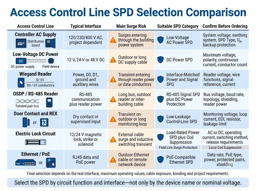
Die Spalte “Vor der Auswahl bestätigen” ist die wichtigste. Sie bestimmt, ob ein SPD elektrisch mit dem angeschlossenen Stromkreis kompatibel ist.
| Leitungsgruppe | Typische Ausrüstung | Vor der Auswahl bestätigen | Zu prüfende SPD-Kategorie |
|---|---|---|---|
| AC-Versorgung des Controllers | Schaltschrank, Netzteil, USV oder PoE-Switch | Systemspannung, Erdungssystem, Einbauposition und Backup-Absicherung | Niederspannungs-AC-Überspannungsschutzgerät |
| Niederspannungs-Gleichstromversorgung | Leser, Tastatur, Schloss, Gegensprechanlage oder Fernbedienung | Maximale Betriebsspannung, Polarität, Stromstärke und Leiteranordnung | Gleichstromversorgung oder kombiniertes Strom-/Signal-Überspannungsschutzgerät |
| Verdrahtung des Wiegand-Lesers | Kartenleser, Tastatur oder biometrischer Leser | D0, D1, Leistung, gemeinsame Referenz- und Hilfsleiter | Schnittstellenangepasster Leistungs- und Signalsschutz |
| OSDP oder RS-485 | Leser, Peripheriemodul oder Fern-Türsteuerung | Busspannung, Baudrate, Topologie, Abschirmung und Leserstromversorgung | RS-485 oder Signalisierungsnetzwerk-SPD |
| Überwachungseingänge | Türkontakt, Sabotageschalter und Anforderung-zum-Verlassen-Gerät | Potentialfreier Kontakt oder überwachter Eingang, Überwachungsspannung, Schleifenstrom sowie Schwellenwerte für Widerstand | SPD mit geringer Leckage für Steuerleitungen |
| Ausgang für Elektroschloss | Magnetschloss, Elektroöffner oder Magnetspule | AC oder DC, Spannung, Laststrom, Schaltmethode und Kabelführung | Lastkompatibler Überspannungsschutz für Stromversorgungs- oder Steuerkreise |
| Ethernet oder PoE | IP-Leser, biometrisches Terminal, Türstation oder Netzwerk-Controller | Datenrate, PoE-Typ, Leistungsbedarf, stromführende Aderpaare und Schirmung | Überspannungsschutz für Ethernet oder PoE |
Beschaffungsfazit: Beginnen Sie nicht mit “einem 24-V-Überspannungsschutz für Zutrittskontrollsysteme.” Beginnen Sie mit einer Liste der Stromkreise und den Betriebsparametern jeder exponierten Schnittstelle.
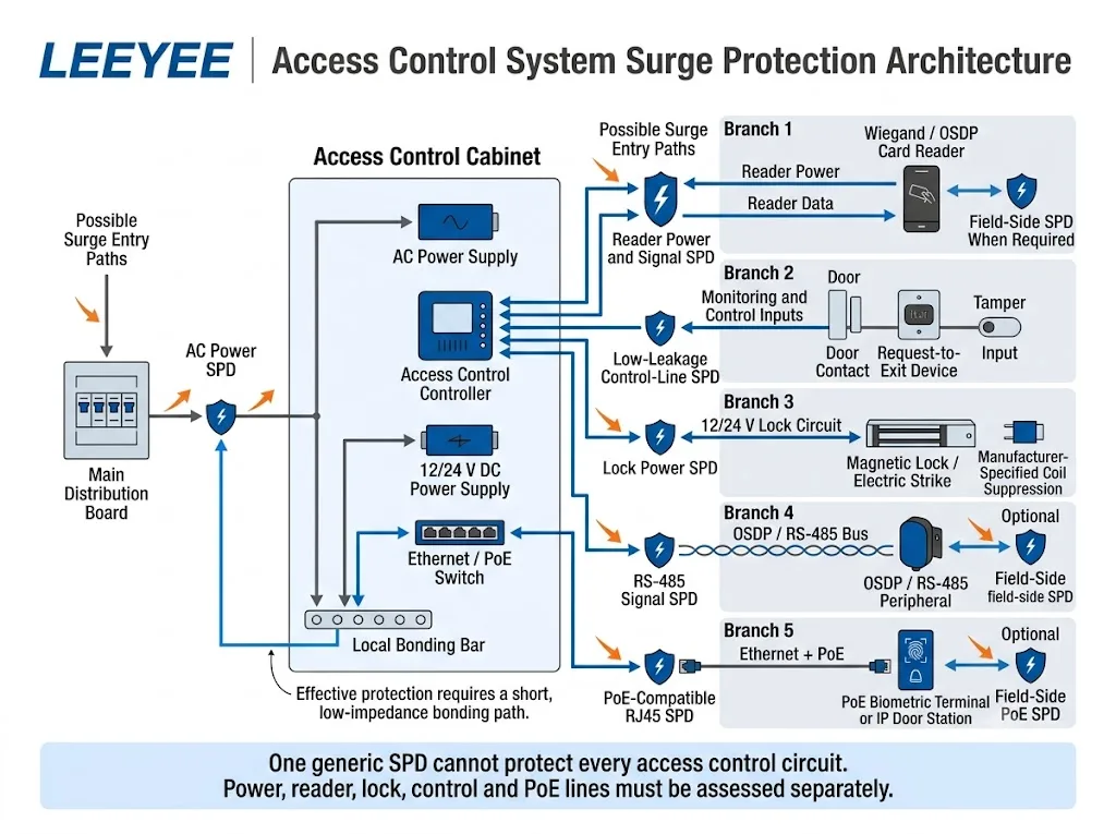
Auf welchen Wegen können Überspannungen in ein Zutrittskontrollsystem eindringen?
Die Stromversorgung des Gebäudes ist nur ein möglicher Eintrittsweg. Leitfähige Feldverkabelungen können transiente Überspannungen ebenfalls in den Controller oder in ein entferntes Zutrittsterminal übertragen.
- AC-Versorgung des Gebäudes: Eine transiente Überspannung kann über das Niederspannungsverteilungssystem den Schaltschrank, das Netzteil, die USV oder den PoE-Switch erreichen.
- Kabel des Außenlesers: Versorgungs- und Kommunikationsleiter des Lesers können induzierten oder leitungsgebundenen transienten Überspannungen ausgesetzt sein.
- Perimeter-Tor oder Drehkreuz: Feldgeräte sind häufig über lange Kabel und separate Metallstrukturen angeschlossen.
- Verkabelung zwischen Gebäuden: Verbundene Bauwerke weisen während eines transienten Ereignisses möglicherweise nicht dasselbe elektrische Potenzial auf.
- Ethernet- und PoE-Kabel: Ein entferntes IP-Terminal führt einen leitfähigen Datenpfad ein und in einem PoE-System auch einen Stromversorgungspfad.
- Lokales Schalten: Relais, Magnetspulen und elektrische Schlösser können Schalttransienten erzeugen, die von extern eintreffenden Überspannungen unterschieden werden müssen.
IEC 62305-4 behandelt den Schutz elektrischer und elektronischer Systeme als Problem eines koordinierten Systems. Die Norm behandelt Überspannungsschutzmaßnahmen, die dazu dienen, dauerhafte Schäden durch den elektromagnetischen Blitzimpuls innerhalb von Bauwerken zu reduzieren. [5]
Exposition nicht ausschließlich anhand des Gerätestandorts beurteilen
Auch ein im Innenbereich installierter Controller kann über ein Kabel beeinträchtigt werden, das mit einem Lesegerät, Tor oder entfernten Gebäude im Außenbereich verbunden ist. Der vollständige Kabelverlauf, die angeschlossenen Geräte und der Potenzialausgleichspfad sind wichtiger als der Standort des Controllers im Innenbereich.
Wie sollte die Stromversorgung des Controllers geschützt werden?
Schutz des AC-Eingangs
Die AC-Versorgung eines Zutrittskontrollschranks sollte als Teil des koordinierten Überspannungsschutzkonzepts für das Stromversorgungssystem des Gebäudes überprüft werden.
Das ausgewählte AC-SPD muss zur tatsächlichen Systemspannung und Erdungsanordnung passen. Das Projekt sollte außerdem den SPD-Typ, die maximal zulässige Dauerspannung, den Spannungsschutzpegel, die Ableitstrom-Nennwerte, den Anschlussmodus, die Kurzschlussbedingungen und den erforderlichen Vorschutz bestätigen.
IEC 61643-11:2025 gilt für SPDs, die an Niederspannungs-AC-Stromversorgungssysteme angeschlossen sind. IEC 61643-01:2024 enthält gemeinsame Anforderungen und Bemessungswerte, die zusammen mit den entsprechenden produktspezifischen Teilen verwendet werden. [1] [2]
Ein AC-SPD schützt nicht jede nachgeschaltete Schnittstelle
Ein korrekt ausgewähltes Netz-SPD begrenzt Überspannungen, die über die AC-Versorgung eintreten. Für die Leitungen von Lesegeräten, Schlössern, RS-485, Ethernet und PoE ist dennoch eine separate Bewertung erforderlich, da sie einen weiteren Überspannungspfad bilden können.
Niederspannungs-Gleichstromversorgung im Feld
Lesegeräte, Schlösser und entfernte Peripheriegeräte verwenden üblicherweise Niederspannungs-Gleichstromversorgungen. Der genaue Betriebsbereich muss der Dokumentation der angeschlossenen Geräte entnommen werden.
Die maximal zulässige Dauerspannung des SPD muss mit der höchsten normalen Netzspannung kompatibel bleiben. Bei einem in Reihe installierten Gerät müssen außerdem der zulässige Dauerstrom und der Serienwiderstand zur angeschlossenen Last passen.
Batteriegepufferte Stromversorgungen erfordern besondere Sorgfalt, da die tatsächliche Betriebsspannung während des Ladevorgangs höher als der nominale Kennzeichnungswert sein kann. Bestätigen Sie vor der Freigabe des SPD den normalen Spannungsbereich, die Batteriespannung beim Laden und die Toleranz des Geräts.
Bedeutung für Käufer: “12 V SPD” oder “24 V SPD” ist keine vollständige Spezifikation. Der Käufer muss außerdem feststellen, ob der Stromkreis Gleichstrom, Lesegerätedaten, RS-485-Kommunikation, einen überwachten Eingang oder eine Kombination dieser Funktionen führt.
Wie sollten Kartenleserleitungen geschützt werden?
Wiegand-, OSDP- und Ethernet-Lesegeräte können eine ähnliche Zutrittskontrollfunktion erfüllen, ihre elektrischen Schnittstellen sind jedoch unterschiedlich. Das SPD muss für die Schnittstelle und nicht für den allgemeinen Begriff “Kartenleser” ausgewählt werden.”
Wiegand-Lesegeräteschaltungen
Eine Wiegand-Lesegeräteverbindung kann Stromversorgung, Masse, D0, D1 und zusätzliche Leiter für Funktionen wie LED, Summer, Sabotageüberwachung oder Haltesteuerung umfassen. Die genauen Leiterfunktionen variieren je nach Lesegerät.
Die Installationsanleitung für HID Signo 25B dokumentiert beispielsweise separate Anschlüsse für Wiegand, RS-485, überwachte Eingänge, DC-Stromversorgung und Ethernet. Dies zeigt, warum vor der Auswahl eines SPD das genaue Gerätemodell und die Verdrahtungsdokumentation geprüft werden müssen. [7]
Bestätigen Sie die Versorgungsspannung des Lesers, den maximalen Strom, den Signalbezug, die Anzahl der Leiter und die Zusatzfunktionen. Ein Überspannungsschutz, der eine übermäßige Belastung verursacht oder einen freiliegenden Leiter ungeschützt lässt, ist möglicherweise nicht geeignet.
OSDP- und RS-485-Leser
Die Security Industry Association beschreibt OSDP als einen offenen Kommunikationsstandard für die Verbindung von Zutrittskontrollzentralen mit Peripheriegeräten wie Lesern. Er bietet eine leistungsfähigere Alternative zum veralteten Wiegand-Verfahren und wird üblicherweise über eine physische RS-485-Verbindung implementiert. [6]
Eine OSDP-Installation kann ein Kommunikationsadernpaar, die Leserversorgung, einen gemeinsamen Bezug und eine Abschirmung umfassen. Der Planer sollte die Bustopologie, die Baudrate, den Kabeltyp, die Erdungsanordnung und die Frage bestätigen, ob mehrere Geräte denselben Bus nutzen.
Ein Produkt mit der Kennzeichnung “RS-485 SPD” ist nicht automatisch für jede OSDP-Installation geeignet. Seine Betriebsspannung, Schutzmodi, Reihenimpedanz, Kapazität, Leiteranordnung und Verbindungsmethode müssen weiterhin überprüft werden.
Proprietäre und multifunktionale Terminals
Einige biometrische Leser, Tastaturen, Video-Türstationen und Fernbedienungen kombinieren mehrere Funktionen in einem Kabel oder Anschluss.
Wenn die Schnittstellengrenzwerte nicht dokumentiert sind, fordern Sie die Verdrahtungspläne der Zentrale und des Lesers an. Vor einem großen Projekt oder einer OEM-Bestellung kann eine Validierung anhand von Stichproben erforderlich sein, insbesondere wenn zulässiger Leckstrom, Kapazität und Reihenwiderstand unbekannt sind.
Wie sollten Türkontakte, REX- und Sabotageeingänge bewertet werden?
Ein Türkontakt kann als potenzialfreies Kontaktgerät beschrieben werden, aber die angeschlossene Zentrale kann dennoch eine geringe Überwachungsspannung oder einen geringen Überwachungsstrom anlegen, um den Zustand normal, Alarm, Leitungsunterbrechung, Kurzschluss oder Sabotage zu erkennen.
Einige Systeme verwenden überwachte Eingänge und Abschlusswiderstände. Die Installationsdokumentation von HID Signo enthält ein Beispiel für überwachte Eingänge für den Austrittsanforderungstaster und die Türposition. [7]
Bevor Sie einen Steuerleitungs-Überspannungsschutz (SPD) hinzufügen, bestätigen Sie:
- Leerlaufüberwachungsspannung
- Normaler Schleifenstrom
- Alarm-, Störungs- und Manipulationsschwellenwerte
- Anordnung des Abschlusswiderstands
- Anzahl der Leiter und gemeinsame Masseanschlüsse
- Maximal zulässiger Ableitstrom des Überspannungsschutzes
- Maximal zulässiger Serienwiderstand und Kapazität
Ein falsch gewählter Überspannungsschutz (SPD) kann die elektrischen Bedingungen am Steuerungseingang verändern. Kurze Innenleitungen erfordern nicht zwingend einen separaten Überspannungsschutz, während Außenleitungen, gebäudeübergreifende Verbindungen und exponierte Leitungen eine detailliertere Projektbewertung erfordern.
Wie sollten elektrische Schlösser und Türöffner geschützt werden?
Stromkreise für elektrische Schlösser können zwei unterschiedliche Arten von transienten Störungen aufweisen. Diese sollten getrennt voneinander bewertet werden.
Über das Feldkabel eintreffende Überspannungen
Ein Kabel, das mit einem externen Magnetschloss, einem elektrischen Türöffner, einem Tor oder einem Solenoid verbunden ist, kann extern erzeugte Transienten in Richtung der Steuerung übertragen.
Der Feldleitungs-Überspannungsschutz (SPD) muss auf die Schaltkreisspannung, den Laststrom, die gegebenenfalls vorhandene Polarität, die Schaltanordnung sowie die Installationsumgebung abgestimmt sein. Die Nennleistung des Steuerungsausgangs und die Anweisungen des Schlossherstellers dienen als maßgebliche Referenz für die endgültige Freigabe.
Induktive Schalttransienten
Eine Schloss- oder Schließblechspule kann beim Unterbrechen des Stromflusses eine lokale Transiente erzeugen. Je nach Gerät kann der Hersteller eine Diode, einen MOV, einen TVS oder eine andere Unterdrückungsmethode vorschreiben.
Die Installationsunterlagen von Allegion für Leser-Steuerungen und elektrische Schließbleche unterscheiden zwischen der Unterdrückung induktiver Lasten und dem Schutz vor anderen transienten Spannungen. Zudem ist erforderlich, dass die Unterdrückungsmethode auf das jeweilige Gerät und den Schaltkreis abgestimmt ist. [8]
Feldleitungsschutz ist nicht gleichbedeutend mit Spulenentstörung
Ein Feldleitungs-Überspannungsschutzgerät (SPD) begrenzt transiente Überspannungen, die über das Kabel eindringen. Eine herstellerspezifische Unterdrückungskomponente kontrolliert die durch das Schloss selbst erzeugten Schalttransienten. Ein Projekt erfordert möglicherweise beides, jedoch sollte keine der Lösungen als automatischer Ersatz für die andere betrachtet werden.
Wie sollten Ethernet- und PoE-Zutrittskontrollgeräte geschützt werden?
IP-Lesegeräte, biometrische Terminals, Video-Türstationen und vernetzte Steuerungen können Ethernet oder PoE nutzen. In einem PoE-System teilen sich Kommunikation und Gleichstromversorgung das strukturierte Verkabelungssystem.
Die Norm IEC 61643-21:2025 schließt Telekommunikations- und Signalnetzwerke, die Strom über dieselbe Leitung bereitstellen, wie etwa PoE, ausdrücklich ein. [3]
Die Anforderungen an Ethernet und PoE sind anhand der geltenden IEEE 802.3-Ausgabe und der Projektdokumentation zu überprüfen. IEEE 802.3-2022 ist der von der IEEE Standards Association gelistete Ethernet-Basisstandard, wobei für die ausgewählten Geräte auch spätere Ergänzungen gelten können. [9]
Ein PoE-Überspannungsschutzgerät (SPD) muss beide Seiten der Schnittstelle abdecken: die Ethernet-Übertragung und die Gleichstromversorgung.
| Parameter | Warum es wichtig ist | Bereitzustellende Informationen |
|---|---|---|
| Ethernet-Leistung | Das SPD darf die Übertragungsleistung nicht unter die projektbezogenen Anforderungen senken. | Erforderliche Ethernet-Datenrate und Kabelkategorie |
| PoE-Typ und Leistung | Der stromführende Pfad muss für das PSE und das gespeiste Gerät ausgelegt sein | PoE-Typ, -Klasse oder maximaler Gerätebedarf |
| Gespeiste Adernpaare | Die Schutzschaltung muss die vom System verwendete Leiteranordnung abdecken | PSE-Modell und Anordnung der gespeisten Adernpaare |
| Abschirmung | Die Schirmkontinuität und der Potenzialausgleich beeinflussen die Installationsmethode | Format für geschirmte oder ungeschirmte Kabel und Steckverbinder |
| Montageumgebung | Außengeräte erfordern möglicherweise ein geeignetes Gehäuse sowie einen entsprechenden Umweltschutz | Innengehäuse, Torsteuerung, Wandgehäuse oder freiliegende Anschlussklemme |
Beschaffungshinweis: Ein RJ45-Stecker allein ist kein Nachweis für die Kompatibilität mit der erforderlichen Ethernet-Geschwindigkeit, PoE-Leistung oder der Belegung der Adernpaare.
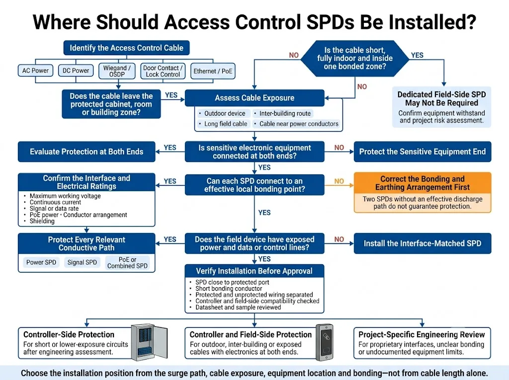
Soll der SPD am Controller oder am Feldgerät installiert werden?
Die Installationsposition kann nicht allein anhand der Kabellänge bestimmt werden. Sie hängt vom Überspannungspfad, der Kabelführung, den Geräten an beiden Enden, dem Potenzialausgleich und der Risikobewertung des Projekts ab.
Der beidseitige Schutz erfordert besondere Aufmerksamkeit, wenn:
- Das Lesegerät, das Gate-Terminal, die Sprechanlage oder der Controller im Außenbereich installiert sind.
- Das Kabel verschiedene Gebäude oder separat geerdete Strukturen miteinander verbindet.
- Das Kabel zu einem Außentor, einem Wachhaus, einem Drehkreuz oder einer Parkplatzeinfahrt führt.
- An beiden Enden ist empfindliche Elektronik angeschlossen.
- Das Kabel verläuft durch verschiedene Blitzschutz- oder elektromagnetische Zonen.
- Die Projektspezifikation oder der Gerätehersteller schreibt einen Schutz an beiden Enden vor.
Ein dedizierter feldseitiger Überspannungsschutz ist möglicherweise nicht erforderlich, wenn:
- Das Kabel ist kurz, ausschließlich für den Innenbereich bestimmt und verbleibt innerhalb einer einzigen Potenzialausgleichszone.
- Nur ein Ende enthält empfindliche elektronische Geräte.
- Die angeschlossenen Geräte verfügen über eine dokumentierte interne Spannungsfestigkeit oder Schutzvorrichtung.
- Die Risikobewertung des Projekts kommt zu dem Schluss, dass ein zusätzlicher Feldschutz nicht erforderlich ist.
Die IEC 61643-22 befasst sich mit der Auswahl, dem Betrieb, dem Standort und der Koordination von Überspannungsschutzgeräten (SPDs) für Telekommunikations- und Signalanlagen. Die IEC 62305-4 ordnet diese Geräte in ein umfassenderes System von Überspannungsschutzmaßnahmen ein. [4] [5]
Zwei Überspannungsschutzgeräte erfordern weiterhin einen wirksamen lokalen Potenzialausgleich
Die Installation eines Überspannungsschutzgeräts (SPD) an beiden Enden garantiert keinen wirksamen Schutz, wenn eines der Geräte nicht über einen geeigneten Potenzialausgleich oder Erdungspfad verfügt. Der Ableitpfad muss zusammen mit dem geschützten Stromkreis überprüft werden.
Welche Installationsdetails beeinflussen die Schutzwirkung?
Platzieren Sie das Überspannungsschutzgerät in der Nähe der geschützten Schnittstelle
Die Verbindung zwischen dem SPD und dem geschützten Anschluss sollte zweckmäßig und direkt sein. Übermäßige Leitungslängen und eine ungünstige Leitungsführung können die Spannung, der das Gerät bei einem schnellen Transienten ausgesetzt ist, erhöhen.
Die endgültige Leiteranordnung muss den Installationsanweisungen für den Überspannungsschutz (SPD) sowie den geltenden Projektanforderungen entsprechen. Verwenden Sie keinen einheitlichen Anschlusslängenwert für alle AC-, DC-, Signal- und PoE-Geräte.
Einen geeigneten Erdungspfad bereitstellen
Das SPD benötigt einen definierten Pfad zur Ableitung von Stoßströmen. Ein langer, indirekter oder schlecht angeschlossener Erdungsleiter kann die Wirksamkeit der Schutzvorrichtung beeinträchtigen.
Bestätigen Sie bei Außengeräten oder separaten Strukturen das lokale Erdungs- und Potenzialausgleichskonzept, bevor Sie ein feldseitiges SPD freigeben.
Freiliegende und geschützte Verkabelung trennen
Vermeiden Sie es, die geschützte Ausgangsleitung nach Möglichkeit parallel zur ungeschützten Eingangsleitung zu verlegen. Eine eng beieinander liegende parallele Leitungsführung kann dazu führen, dass transiente Energie in den geschützten Bereich einkoppelt.
Vorhandenen Schutz überprüfen
Die Anlage verfügt möglicherweise bereits über einen AC-Überspannungsschutz an der Verteilung, einen weiteren Überspannungsschutz im Steuerschrank oder interne Schutzkomponenten in den angeschlossenen Geräten.
Bestätigen Sie den Zweck und die Nennwerte jedes Geräts. Es sollte nicht davon ausgegangen werden, dass ein interner Anschlussschutz einen externen Schutz ersetzt, es sei denn, die Gerätedokumentation stützt diese Schlussfolgerung eindeutig.
Welche Normen und Zertifikate sollten Käufer prüfen?
Das relevante Dokument hängt vom zu schützenden Stromkreis ab. Es sollte nicht davon ausgegangen werden, dass ein Zertifikat gleichzeitig Wechselstrom, Niederspannungssteuerleitungen sowie Ethernet- oder PoE-Produkte abdeckt.
| Schutzbereich | Zu bewertendes Dokument | Käuferverifizierung |
|---|---|---|
| AC-Leistungs-SPD | IEC 61643-11 sowie die geltende nationale Umsetzung oder Projektspezifikation | Genaue Modellbezeichnung, Spannung, SPD-Typ, Schutzmodi, Nennwerte und Zertifikatsumfang |
| Signal-, Steuerungs- und PoE-Überspannungsschutzgeräte | IEC 61643-21, unter Verwendung von IEC 61643-22 als Anwendungsleitfaden | Genaue Schnittstelle, Spannung, Stromstärke, Übertragungsleistung und geprüfter Modellbereich |
| Nordamerikanische Datenstromkreise | UL 497B kann für Schutzvorrichtungen in Datenkommunikations- und Brandmeldeanlagen relevant sein | Bestätigen Sie die genaue Produktauflistung und Kategorie in den aktuellen UL-Zertifizierungsunterlagen |
| Ethernet- und PoE-Schnittstelle | Anwendbare IEEE 802.3-Ausgabe, Änderungen und Gerätedokumentation | Datenrate, PoE-Typ, Klasse, versorgte Adernpaare und maximaler Strom |
| Zutrittskontrollsysteme | Installationsunterlagen für Controller, Lesegeräte, Schlösser und Netzwerkgeräte | Anweisungen zu Anschlussbegrenzungen, Verdrahtung, Entstörungsmethoden und Erdung |
Fazit zur Zertifizierung: Überprüfen Sie den Zertifikatsinhaber, die genaue Modellnummer, die geprüften Nennwerte, den Ausgabestatus und den Geltungsbereich. Ein Logo auf einer Broschüre ist kein ausreichender Nachweis.
UL 497B ist von UL Standards & Engagement als Norm für Schutzgeräte in Datenkommunikations- und Brandmeldeanlagen gelistet. Die Anwendbarkeit hängt weiterhin vom genauen Produkt und der beabsichtigten Installation ab. [10]
Für Projekte in Nordamerika sollte der Käufer den genauen Zertifizierungsnachweis in UL Product iQ oder der entsprechenden Zertifizierungsdatenbank prüfen, anstatt sich ausschließlich auf die Angaben des Lieferanten zu verlassen. [10]
Auswahlprozess für Überspannungsschutzgeräte (SPD) für Zutrittskontrolle
-
Zeichnen Sie die Systemarchitektur.
Kennzeichnen Sie den Verteilerkasten, das Netzteil, die Steuerung, die Lesegeräte, die Schlösser, die Überwachungsgeräte, den Netzwerk-Switch sowie jedes leitfähige Feldkabel. -
Klassifizieren Sie jeden Stromkreis.
Identifizieren Sie Wechselstrom, Gleichstrom, Wiegand, OSDP oder RS-485, überwachte Kontakte, Schließausgänge, Ethernet oder PoE. -
Erfassen Sie die elektrischen Grenzwerte.
Bestätigen Sie die maximale Betriebsspannung, den Laststrom, den Signalpegel, die Datenrate, die Aderzahl, die Abschirmung sowie die zulässige Leitungsbelastung. -
Beurteilen Sie die Leitungsführung.
Prüfen Sie, ob das Kabel für den Innen- oder Außenbereich, für die Gebäude-zu-Gebäude-Verbindung, in der Nähe von Stromleitern oder in Verbindung mit einer separaten Metallstruktur verlegt wird. -
Wählen Sie die SPD-Kategorie aus.
Wählen Sie je nach Stromkreis einen AC-Überspannungsschutz, DC-Überspannungsschutz, Signal-Überspannungsschutz, RS-485-Überspannungsschutz, Steuerleitungs-Überspannungsschutz oder PoE-Überspannungsschutz aus. -
Wählen Sie den Schutzort aus.
Entscheiden Sie, ob ein Schutz an der Steuerung, am Gebäudeeingang, an den Feldgeräten oder an beiden Enden erforderlich ist. -
Überprüfen Sie die Kompatibilität und die Unterlagen.
Überprüfen Sie Erdung, Montage, Leckstrom, Widerstand, Bandbreite, PoE-Leistung, Zertifikatsumfang und Geräteanweisungen. -
Schließen Sie die Projektgenehmigung ab.
Überprüfen Sie den Schaltplan, das Produktdatenblatt und die Leistung des Musters, bevor Sie eine Großbestellung aufgeben oder eine OEM-Freigabe erteilen.
Typische technische Szenarien
Innentür für Büroräume
Das Steuergerät und das Lesegerät befinden sich im selben Gebäude, und das Feldkabel verbleibt innerhalb eines Potenzialausgleichsbereichs. Beginnen Sie mit dem Schutz der Wechselstromversorgung und der Bewertung der Kabelführung. Ein separater Überspannungsschutz für die Leserleitung sollte auf Basis der Gerätefestigkeit und des Projektrisikos entschieden und nicht automatisch hinzugefügt werden.
Außenbereich-Perimeter-Lesegerät
Das Lesegerät ist im Außenbereich montiert, während sich das Steuergerät im Innenbereich befindet. Bewerten Sie die Stromversorgungs- und Kommunikationsleitungen des Lesegeräts separat. Ein Schutz am Steuergerät und in der Nähe des Außenlesegeräts kann sinnvoll sein, sofern ein effektiver lokaler Potenzialausgleich vorhanden ist.
Biometrisches PoE-Terminal am Tor
Überprüfen Sie die Ethernet-Datenrate, den PoE-Typ, die maximale Leistung, die Kabelabschirmung und das Außengehäuse. Kontrollieren Sie die PoE-Switch-Seite, den Gebäudeeintritt und das Feldterminal gemäß der Kabelführung und dem Erdungskonzept.
Gebäudeübergreifende Zutrittskontrolle
Leitfähige Verkabelungen zwischen Gebäuden können Geräte Potenzialunterschieden aussetzen. Überprüfen Sie sämtliche Strom-, Kommunikations- und Steuerungswege in Verbindung mit dem Erdungs- und Potenzialausgleichskonzept beider Gebäude.
Magnetverschluss mit überwachtem Türkontakt
Der Schließerausgang und der Türkontakteingang erfordern unterschiedliche Prüfungen. Der Schließerpfad muss den Laststrom führen und erfordert möglicherweise eine Spulenunterdrückung, während der überwachte Eingang einen SPD mit geringem Leckstrom erfordern kann, der die Überwachungsschwellen nicht verändert.
Häufige Fehler bei Auswahl und Installation
- Nur den AC-Eingang schützen. Feld- und Netzwerkkabel können separate Eintrittspfade für Überspannungen bilden.
- Verwendung eines 24-V-Überspannungsschutzes (SPD) für jeden Stromkreis. Ein Schließausgang, ein Wiegand-Signal und ein OSDP-Bus haben unterschiedliche Anforderungen.
- Wiegand und OSDP als identisch behandeln. Ihre Kommunikations- und Leiteranordnungen unterscheiden sich.
- Die Auswahl eines RJ45-Überspannungsschutzes allein anhand des äußeren Erscheinungsbildes des Steckers. Ethernet-Geschwindigkeit, PoE-Leistung und die versorgten Adernpaare müssen ebenfalls übereinstimmen.
- Die Stromaufnahme des elektrischen Schlosses wird ignoriert. Ein Überspannungsschutz für Kleinsignale ist möglicherweise nicht für die Last des Schlosses geeignet.
- Hinzufügen übermäßiger Leckströme zu einem überwachten Eingang. Der SPD kann die Erkennung von Normal-, Alarm- oder Fehlerzuständen beeinträchtigen.
- Verwechslung von Spulenunterdrückung mit Feldleitungs-Überspannungsschutz.
- Installation von zwei SPDs ohne geeigneten lokalen Potenzialausgleich.
- Gemeinsame Verlegung von geschützter und ungeschützter Verkabelung.
- Akzeptieren eines Zertifikats ohne Überprüfung des genauen Modells und des Geltungsbereichs der Zertifizierung.
Vor der Bestellung von Überspannungsschutzgeräten (SPD) für Zutrittskontrolle
Senden Sie die folgenden Informationen an den Lieferanten. Ein Systemschaltplan und Leitungsdaten sind hilfreicher als ein Foto des Steuergeräts oder eine Anfrage für einen allgemeinen Überspannungsschutz für Zutrittskontrollsysteme.
Systemarchitektur
- Modelle von Steuergeräten und Peripheriegeräten
- Anzahl und Art der Türen
- Innen- oder Außenausstattung
- Verkabelung innerhalb eines Gebäudes oder zwischen Gebäuden
- Kabelweg und ungefähre Länge
Leistungsparameter
- AC oder DC
- Nenn- und Maximalspannung
- Maximaler Dauer- oder Laststrom
- Erdungsanordnung
- Batteriegestützte oder nicht gestützte Versorgung
Leser und Kommunikation
- Wiegand, OSDP, RS-485 oder Ethernet
- Versorgungsspannung des Lesegeräts
- Aderanzahl und Aderfunktionen
- Baudrate oder Ethernet-Datenrate
- Geschirmtes oder ungeschirmtes Kabel
Schließ- und Überwachungsstromkreise
- Schlosstyp und Betriebsstrom
- AC- oder DC-Schlossausgang
- Trockenkontakt oder überwachter Eingang
- Anordnung des Abschlusswiderstands
- Vom Hersteller geforderte Entstörung
PoE-Details
- PoE-Typ oder -Klasse
- PSE- und Powered-Device-Modelle
- Maximale Geräteleistung
- Erforderliche Datenrate
- Kabelkategorie und Schirmung
Beschaffungsanforderungen
- Hutschienen-, Wand- oder Direktmontage
- Erforderlicher Standard oder Zertifikat
- Menge
- OEM-Kennzeichnung und Verpackung
- Anforderungen für die Genehmigung von Datenblättern und Mustern
Wie LEEYEE eine Konfiguration für ein Überspannungsschutzgerät (SPD) für Zutrittskontrolle prüft
Ein Zutrittskontrollprojekt sollte schaltkreisweise überprüft werden. LEEYEE betrachtet einen generischen Produktnamen nicht als Nachweis für die Kompatibilität jeder Schnittstelle.
1. Stromkreisidentifizierung
Trennen Sie die Pfade für AC, DC, Lesegeräte, überwachte Eingänge, Schlösser, serielle Kommunikation und PoE.
2. Parameterabgleich
Vergleichen Sie Betriebsspannung, Stromstärke, Datenleistung, Anschlussart und Einbauposition.
3. Dokumentenprüfung
Überprüfen Sie das genaue Produktdatenblatt, die Verdrahtungsanweisungen und gegebenenfalls den modellspezifischen Zertifizierungsumfang.
4. Musterfreigabe
Verwenden Sie eine Muster- oder Schnittstellenprüfung, wenn ein proprietäres Gerät oder ein nicht dokumentierter Anschluss zu Unsicherheiten führt.
Projektumfang: Das endgültige Modell kann nicht allein anhand dieses Artikels ausgewählt werden. Die Parameter für Controller, Lesegerät, Schloss, Netzwerk und Standort müssen für das tatsächliche Projekt bestätigt werden.
Benötigen Sie eine Prüfung der Konfiguration für ein Überspannungsschutzgerät (SPD) für Zutrittskontrolle?
Bitte teilen Sie die Steuerspannung, die Leserschnittstelle, den Schlossstrom, die Anordnung der Überwachungseingänge, den PoE-Bedarf, die Kabelführung sowie die geplanten Installationspositionen mit. LEEYEE kann die erforderlichen SPD-Kategorien für OEM-Bestellungen oder Projektkonfigurationen prüfen.
LEEYEE ist ein spezialisierter Anbieter von Überspannungs- und Niederspannungsschutzlösungen. CNSPD ist die auf Überspannungsschutz fokussierte Plattform von LEEYEE für technische Einkäufer weltweit.
Häufig gestellte Fragen
Benötigt jedes Zutrittskontrollsystem an jeder Leitung einen Überspannungsschutz (SPD)?
Nein. Die Notwendigkeit hängt von der Kabelführung, der Exposition, den angeschlossenen Geräten, der internen Spannungsfestigkeit, dem vorhandenen Schutz und dem Projektrisiko ab. Dennoch sollte jeder leitfähige Pfad bewertet werden.
Benötigt ein Kartenleserkabel einen Überspannungsschutz?
Für Außenkabel, gebäudeübergreifende Leitungen oder exponierte Leserkabel ist ein Schutz eher erforderlich. Die endgültige Entscheidung sollte die Schnittstelle, die Belastbarkeit der Geräte, die Kabelführung und die Erdungskonfiguration berücksichtigen.
Kann dasselbe SPD sowohl Wiegand- als auch OSDP-Leser schützen?
Nur wenn die dokumentierte Betriebsspannung, die Leiteranordnung, die Serienimpedanz, die Kapazität und die Schutzmodi für beide Schnittstellen geeignet sind. Von Kompatibilität sollte nicht ausgegangen werden.
Verwendet ein OSDP-Leser ein RS-485-SPD?
OSDP verwendet üblicherweise eine RS-485-Physikschicht, dennoch muss der Überspannungsschutz (SPD) auf die tatsächliche Busspannung, Baudrate, Topologie, Erdungskonfiguration und die Stromversorgungsleitungen des Lesers abgestimmt sein.
Kann ein potenzialfreier Eingang mit einem beliebigen Signal-SPD verwendet werden?
Nein. Die Steuereinheit kann eine Überwachungsspannung anlegen oder Widerstandsschwellenwerte kontrollieren. Leckströme, Serienwiderstände und Kapazitäten des SPD dürfen die normale Erkennung von Alarm-, Unterbrechungs- oder Manipulationszuständen nicht beeinträchtigen.
Benötigt ein Haftmagnet einen Überspannungsschutz?
Ein freiliegendes Schlosskabel erfordert möglicherweise einen Überspannungsschutz für die Feldleitung. Das Schloss benötigt zudem gegebenenfalls eine vom Hersteller spezifizierte Induktionslastunterdrückung. Hierbei handelt es sich um separate Funktionen.
Benötigt ein PoE-Zugangsleser einen RJ45-Überspannungsschutz?
Der Schutz erfordert besondere Aufmerksamkeit bei Außenverkabelungen, Verbindungen zwischen Gebäuden oder freiliegenden Kabeln. Der Überspannungsschutz muss die erforderliche Ethernet-Geschwindigkeit, PoE-Leistung, die versorgten Adernpaare sowie die Abschirmungskonfiguration unterstützen.
Sollte ein Außenlesegerät an beiden Enden geschützt werden?
Ein beidseitiger Schutz kann sinnvoll sein, wenn an beiden Enden eines freiliegenden Kabels empfindliche Elektronik angeschlossen ist. Die Entscheidung muss zudem den lokalen Potenzialausgleich, Schutzzonen, Geräteanweisungen sowie Projektrisiken berücksichtigen.
Welche Informationen werden für eine Bestellung von OEM-Überspannungsschutzgeräten (SPD) für die Zugangskontrolle benötigt?
Bitte stellen Sie das Systemdiagramm, die Betriebsspannung, den maximalen Strom, die Leserschnittstelle, die Überwachungsmethode, Anforderungen an Ethernet oder PoE, die Aderanzahl, die Kabelführung, den Installationsort, die erforderliche Zertifizierung sowie die Stückzahl bereit.
Referenzen
- Internationale Elektrotechnische Kommission, IEC 61643-01:2024, Überspannungsschutzgeräte für Niederspannung – Teil 01: Allgemeine Anforderungen. Offizielle IEC-Veröffentlichungsseite.
- Internationale Elektrotechnische Kommission, IEC 61643-11:2025, Überspannungsschutzgeräte für Niederspannung – Teil 11: Überspannungsschutzgeräte für den Einsatz in Niederspannungsanlagen – Anforderungen und Prüfungen. Offizielle IEC-Veröffentlichungsseite.
- Internationale Elektrotechnische Kommission, IEC 61643-21:2025, Überspannungsschutzgeräte für den Einsatz in Telekommunikations- und signalverarbeitenden Netzwerken – Leistungsanforderungen und Prüfverfahren. Offizielle IEC-Veröffentlichungsseite.
- Internationale Elektrotechnische Kommission, IEC 61643-22:2015, Überspannungsschutzgeräte für Niederspannung – Teil 22: Überspannungsschutzgeräte für den Einsatz in Telekommunikations- und signalverarbeitenden Netzwerken – Auswahl und Anwendungsgrundsätze. Offizielle IEC-Veröffentlichungsseite.
- Internationale Elektrotechnische Kommission, IEC 62305-4:2024, Blitzschutz — Teil 4: Elektrische und elektronische Systeme in baulichen Anlagen. Offizielle IEC-Veröffentlichungsseite.
- Security Industry Association, Open Supervised Device Protocol (OSDP) und OSDP im Vergleich zu Wiegand. Offizielle SIA OSDP-Seite; Offizielle Vergleichsseite.
- HID Global, Installationsanleitung für den biometrischen Leser/Controller HID Signo 25B, einschließlich dokumentierter Wiegand-, RS-485-, überwachter Eingangs-, Gleichstrom- und Ethernet-Anschlüsse. Offizielle HID-Installationsanleitung.
- Allegion, Installations- und Verdrahtungsanleitung für ISONAS Pure IP Reader-Controller und Von Duprin Installationsanleitung für den elektrischen Türöffner 6400, einschließlich der Herstellerhinweise zur Unterdrückung induktiver Lasten. Offizielles Handbuch für Leser-Controller; Offizielle Anleitung für elektrische Türöffner.
- IEEE Standards Association, IEEE 802.3-2022, IEEE-Standard für Ethernet. Offizielle IEEE-Standardseite.
- UL Standards & Engagement, UL 497B, Schutzvorrichtungen für Datenkommunikations- und Brandmeldeschaltkreise, sowie die UL Solutions Product iQ Zertifizierungsdatenbank. Offizielle UL-Standardseite; UL Product iQ.
