
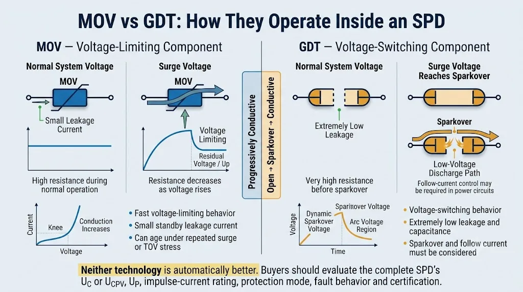
MOV and GDT are both used for surge protection, but they operate differently. An MOV progressively limits voltage. A GDT or spark gap remains highly resistive until sparkover creates a conductive discharge path.
For engineering and OEM procurement, the real question is not simply which component is better. The buyer must determine which complete SPD structure matches the application, system voltage, protection mode, surge waveform, fault conditions and certification requirements.
Table of Contents
Quick Answer: What Is the Difference Between MOV and GDT?
MOVs are voltage-limiting components. Their resistance decreases progressively as voltage rises. They are widely used in AC Type 2 SPDs, PV DC SPDs and other power-protection circuits because they provide compact and predictable voltage-limiting behavior.
GDTs and power spark gaps are voltage-switching components. They remain highly resistive during normal operation and switch into a conductive discharge state after sparkover. They are useful where very low leakage, low capacitance or high normal-state insulation is required.
Neither technology is automatically better. Compare the complete SPD's Uc or Ucpv, Up, Iimp, In, Imax, protection mode, follow-current behavior, disconnection structure, short-circuit capability and certification. [1] [8]
MOV vs GDT: The Core Differences
The table below gives the direct answer most engineering buyers need before reviewing the deeper technical sections.
Swipe horizontally to view the complete comparison table.
| Comparison point | MOV | GDT / spark-gap technology | Buyer interpretation |
|---|---|---|---|
| Operating principle | Voltage-limiting nonlinear resistance | Voltage-switching after sparkover | The two technologies control transient voltage in different ways. |
| Normal-state leakage | Small leakage current is normally present | Extremely low leakage before sparkover | Leakage and insulation can matter in N-PE, signal and monitoring applications. |
| Voltage behavior | Voltage follows the MOV's nonlinear current-voltage curve | Voltage rises to dynamic sparkover, then falls toward the arc-voltage region | Compare the complete SPD's tested Up, not only the component description. |
| Response behavior | Fast material response, but wiring and inductance still affect the result | Sparkover depends on voltage rise rate and device structure | Generic nanosecond claims do not replace complete SPD test data. |
| Surge-current handling | Can be high when correctly sized, connected and thermally protected | Can be very high after ignition in a suitably designed device | Always compare the waveform, current per pole and test classification. |
| Capacitance | Generally higher | Generally very low | GDT technology is often useful in high-frequency and signal protection. |
| Aging | Repeated surges, heat and TOV can change leakage and varistor characteristics | Severe discharge duty can erode electrodes or alter sparkover behavior | Neither component family should be described as infinitely durable. |
| Follow current | Does not create the same arc follow-current issue as a spark gap | Power-source current may continue after ignition unless the design extinguishes or controls it | Follow-current performance is critical in power and some DC applications. |
| Common applications | AC Type 2, PV DC and power-input voltage-limiting protection | N-PE modules, signal primary stages and many Type 1 lightning-current applications | These are common uses, not universal rules. |
| Main purchasing risk | Ignoring TOV, thermal disconnection and end-of-life behavior | Ignoring dynamic sparkover, front voltage and follow current | Approve the complete SPD, not only the internal component. |
Which Structure Is Commonly Used in Each SPD Application?
Swipe horizontally to view the complete application table.
| Application | Common structure | Main reason | What to confirm |
|---|---|---|---|
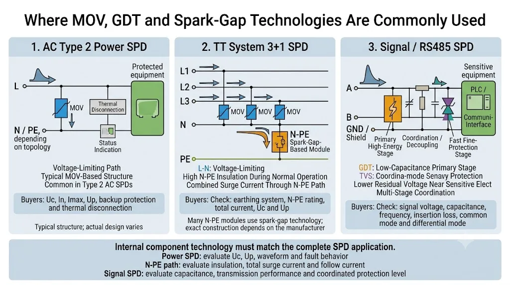
| AC Type 2 distribution-board SPD | Frequently MOV-based | Compact voltage-limiting protection | Uc, In, Imax, Up, thermal disconnection and backup device |
| TT 1+1 or 3+1 N-PE path | Frequently spark-gap-based | High N-PE insulation and very low normal leakage | N-PE total current, system topology, Uc and Up |
| Type 1 service entrance | Tested spark-gap, MOV or coordinated Type 1 structure | Must withstand the declared lightning impulse | Iimp, 10/350 μs waveform, Up and follow-current behavior |
| PV DC SPD | PV-specific voltage-limiting structures are common | Voltage limiting with safe DC fault disconnection | Ucpv, Iscpv, In, Imax or Iimp, Up and certificate scope |
| RS485 or signal SPD | GDT plus coordinated fine protection is common | Low capacitance with a lower final residual voltage | Signal voltage, capacitance, frequency, Up and test category |
| Low-leakage hybrid protection | Series GDT-and-MOV structure may be used | The GDT can isolate the MOV from continuous operating voltage | MCOV, front protection voltage, clamping behavior and testing |
LEEYEE OEM Review Focus
For project matching, the review should begin with system voltage, earthing arrangement, protection mode and applicable SPD classification. Internal MOV, GDT or spark-gap technology is then evaluated together with Up, surge-current waveform, fault behavior, disconnection, product label and certificate scope.
How Does an MOV Work Inside a Surge Protective Device?
MOV: Voltage-Limiting Behavior
MOV means metal oxide varistor. Its resistance changes nonlinearly with applied voltage. At normal system voltage, the component remains at high resistance and carries a small leakage current. As transient voltage rises, resistance falls and surge current is diverted through the protection path.
A Bare MOV Is Not a Complete SPD
A practical power SPD also depends on thermal disconnection, internal conductor layout, insulation, status indication, terminals, enclosure construction and coordination with integrated or external backup protection.
Repeated surge stress, excessive operating voltage, heat or TOV can increase MOV leakage and temperature. Safe disconnection and clear end-of-life indication are therefore important parts of the complete design. [10]
The number or diameter of MOV discs does not prove complete SPD performance. Material formulation, connection method, thermal control, conductor dimensions and complete-product testing all affect the result.
How Does a GDT or Spark Gap Work Inside an SPD?
GDT: Voltage-Switching Behavior
A gas discharge tube contains two or three electrodes in a sealed enclosure with a controlled gas mixture. At normal voltage, the gap is non-conductive and provides very high insulation resistance. When the transient reaches its dynamic sparkover condition, the gas ionizes and creates a conductive discharge path.
The Follow-Current Question
Once a power spark gap has ignited, the connected source may continue supplying current through the conductive path after the original transient has passed. This is known as follow current.
The complete power SPD must extinguish, interrupt or safely coordinate this current. High impulse-current capability alone does not prove suitability for every AC or DC source.
IEC 61643-312 defines the characteristics and applications of GDT components, while specifically distinguishing those components from the complete requirements of a finished SPD. [7]
Is a GDT the Same as Every Power Spark Gap?
No. A GDT is one type of gas-filled voltage-switching component, but the term spark gap covers a wider range of structures.
- A discrete GDT is normally a compact sealed component with two or three electrodes.
- A power SPD may use larger encapsulated, triggered, carbon, graphite or multi-electrode spark-gap structures.
- Type 1 spark-gap modules may include dedicated arc chambers, triggering systems and follow-current-extinguishing structures.
Instead of asking only whether an SPD contains a GDT, ask whether the protection path is voltage-limiting or voltage-switching, what impulse waveform applies, what follow-current behavior is declared and how the complete SPD was tested.
Response Time, Dynamic Sparkover and Voltage Protection Level
Many component comparisons claim that an MOV is faster and a GDT is slower. That statement is too simple for complete SPD selection.
A GDT's dynamic sparkover voltage depends partly on the voltage rise rate. A steep transient can create a brief front voltage before the conductive discharge state is established. Series GDT-and-MOV structures may therefore have a front protection voltage that must be considered during coordination. [11]
MOV behavior is also affected by lead length, internal conductor inductance, current amplitude and test waveform. The voltage appearing at the equipment is the result of the complete SPD and installation, not a generic component response-time number.
Use the declared voltage protection level Up, the applicable impulse waveform, protection mode and installation requirements. Do not approve an SPD from an advertised nanosecond value alone.
Why Do Many N-PE Modules Use Spark-Gap Technology?
In TT systems and some TN-S arrangements, 1+1 or 3+1 topologies are commonly used. Phase conductors are protected toward neutral through voltage-limiting paths, while neutral is connected to protective earth through a voltage-switching N-PE module.
Typical 1+1 Arrangement
- L-N: commonly an MOV-based voltage-limiting path
- N-PE: commonly a spark-gap-based switching path
- Used in suitable single-phase TT and TN-S applications
Typical 3+1 Arrangement
- L1/L2/L3-N: commonly MOV-based protection paths
- N-PE: one high-capacity voltage-switching protection path
- Used in suitable three-phase TT and TN-S applications
The N-PE switching path maintains high insulation and very low leakage during normal operation. During a surge, it carries the combined impulse current from neutral toward the protective bonding system. [14]
Confirm whether the stated value is total current, current per protection mode or current per pole. Products with similar 1+1 or 3+1 labels can have different N-PE discharge capacities.
How MOV and GDT Structures Differ by SPD Application
Distribution Boards and Control Panels
MOV-based structures are common in Type 2 AC SPDs because they provide compact voltage-limiting protection for distribution-level surge currents.
- Confirm Uc, In, Imax and Up.
- Check thermal disconnection and backup protection.
- Match the protection mode to the earthing system.
Lightning-Current Entry Points
Type 1 products can use purpose-designed spark gaps, MOV assemblies or coordinated structures. Type 1 classification is based on complete-product testing, not the component name.
- Verify Iimp with the 10/350 μs waveform.
- Confirm Up and current per pole.
- Check follow-current and downstream coordination.
Combiner Boxes and Solar Inverters
Voltage-limiting varistor structures are common in PV DC SPDs, but the important question is whether the complete device can safely disconnect under DC overload and fault conditions.
- Confirm Ucpv, Iscpv, In, Imax or Iimp and Up.
- Check polarity and PV-specific failure behavior.
- Verify the certificate scope against the ordered model.
RS485, Telecom and PLC Interfaces
GDTs are often used as a low-capacitance high-energy primary stage. A coordinated TVS or other fine-protection stage can then limit the remaining voltage close to sensitive electronics.
- Confirm signal voltage and maximum operating voltage.
- Check capacitance, frequency and insertion loss.
- Verify common-mode and differential-mode protection.
AC power, PV DC and telecommunications or signalling SPDs are covered by different product requirements. A component-level comparison therefore cannot replace application-specific complete-product selection. [2] [4] [6]
Why Are MOV and GDT Sometimes Combined?
MOV and GDT technologies can be connected in series or coordinated in a multi-stage circuit. The goal is to combine useful characteristics, not simply to add their current ratings together.
Series GDT-and-MOV Protection
In a series hybrid, the GDT can isolate the MOV from continuous system voltage during normal operation. This can reduce standby leakage through the MOV and reduce continuous electrical stress. After sparkover, the MOV contributes voltage-limiting behavior. [12] [13]
Coordinated Signal Protection
A GDT can handle the higher-energy incoming surge, while a downstream suppressor limits the remaining transient near the protected interface. A coordination element may be needed so the primary stage operates before the fine-protection stage is overloaded.
Check MCOV or operating voltage, front protection voltage, clamping behavior, leakage, current waveform and complete-product testing. Incorrectly coordinated components can still provide poor protection.
MOV vs GDT Aging, Failure and Safety
MOV Stress and End of Life
Repeated impulses, high ambient temperature, excessive continuous voltage and TOV can change MOV characteristics. Leakage and self-heating may increase, making thermal disconnection and status indication important.
GDT and Spark-Gap Wear
Severe discharge duty can erode electrodes or change sparkover characteristics. Power spark-gap designs must also control arc extinction, follow current and insulation after operation.
The safety of the finished product also depends on internal disconnectors, backup protection, insulation distances, terminals, enclosure material, indicator systems and short-circuit withstand.
An MOV, GDT or thermal-protector component certificate does not prove that the assembled DIN-rail SPD complies with the applicable complete-product standard.
OEM and Engineering Buyer Checklist
Do not begin an RFQ with only “MOV SPD” or “GDT SPD.” Begin with the system and required protection performance.
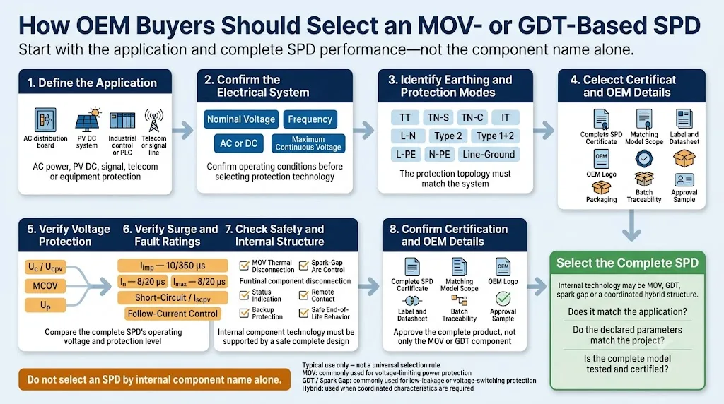
- Application: AC distribution, PV DC, telecom, industrial signal, control panel or equipment-level protection.
- System voltage: nominal voltage, maximum continuous voltage and frequency where applicable.
- Earthing system: TT, TN-S, TN-C, IT, floating DC or grounded DC.
- SPD category: Type 1, Type 2, Type 1+2, Type 3, PV SPD or signal SPD.
- Protection mode: L-N, L-PE, N-PE, L-L, positive-negative or conductor-earth.
- Voltage ratings: Uc, Ucpv, MCOV and declared Up.
- Current ratings: Iimp, In and Imax with the applicable 10/350 μs or 8/20 μs waveform.
- Fault behavior: short-circuit rating, Iscpv, follow-current control and backup protective device.
- Safety structure: thermal disconnection, arc control, insulation, indication and remote contact.
- Certification: complete-model test report, certificate scope, standard edition and matching product label.
- Mechanical requirements: pole configuration, DIN width, terminals and replacement-module compatibility.
- OEM requirements: logo, model code, label, packaging, manual, barcode and batch traceability.
Recommended RFQ Information
Six Common MOV and GDT Procurement Mistakes
Frequently Asked Questions
Is MOV or GDT better for surge protection?
Neither is universally better. MOVs are widely used for voltage-limiting power protection. GDTs and spark gaps are useful where very low leakage, low capacitance or voltage-switching behavior is required. The correct choice depends on the complete SPD application and ratings.
Is a GDT the same as a spark gap?
A GDT is a sealed gas-filled spark-gap component. However, a power SPD may use larger or specially engineered spark-gap structures that should not automatically be described as ordinary discrete GDTs.
Why is a spark gap used between N and PE?
A voltage-switching N-PE module provides high insulation and very low leakage during normal operation. During a surge, it switches into conduction and carries the combined impulse current toward PE.
Does a Type 1 SPD always use a spark gap?
No. Type 1 is a complete-product test classification. A Type 1 product may use spark-gap, MOV or coordinated technologies if the finished SPD passes the applicable tests and declares the required ratings.
Does a Type 2 SPD always use an MOV?
MOV technology is very common in Type 2 power SPDs, but the classification is not defined only by the component. Some protection modes, especially N-PE paths, may use voltage-switching technology.
Can MOV and GDT be used together?
Yes. They may be integrated in a series hybrid or coordinated in a multi-stage circuit. Front voltage, current sharing, leakage and complete-product testing must still be verified.
What should a buyer compare instead of response time alone?
Confirm the complete SPD's Uc or Ucpv, Up, impulse-current rating and waveform, protection mode, fault behavior, disconnection structure and certification.
Related LEEYEE Technical Guides
Need to Confirm the Right SPD Structure for an OEM Order?
Send LEEYEE your system voltage, earthing arrangement, required SPD category, current ratings, certification market and private-label requirements. We will help identify the parameters that should be confirmed before sample approval.
Authoritative References
- IEC, “IEC 61643-01:2024 — Common requirements for low-voltage surge protective devices.” View IEC publication
- IEC, “IEC 61643-11:2025 — SPDs connected to AC low-voltage power systems.” View IEC publication
- IEC, “IEC 61643-12:2020 — Selection and application principles for AC power SPDs.” View IEC publication
- IEC, “IEC 61643-31:2018 — Requirements and test methods for SPDs for photovoltaic installations.” View IEC publication
- IEC, “IEC 61643-41:2025 — SPDs connected to low-voltage DC power systems.” View IEC publication
- IEC, “IEC 61643-21:2025 — SPDs connected to telecommunications and signalling networks.” View IEC publication
- IEC, “IEC 61643-312:2013 — Selection and application principles for gas discharge tubes.” View IEC publication
- Phoenix Contact, “Surge protection basics.” View technical information
- Phoenix Contact, “Spark gap technology.” View technical information
- Bourns, “Tips on Selecting the Right MOV Surge Suppressor.” View technical paper
- Bourns, “Understanding Front Protection Voltage and Its Effects on Surge Protection.” View technical paper
- Eaton Bussmann, “MOVGT Integrated MOV and GDT Overvoltage Protection.” View technical information
- Littelfuse, “Combining GDTs and MOVs for Surge Protection of AC Power Lines.” View application note
- DEHN, “N-PE spark-gap-based lightning current arresters for 1+1 and 3+1 circuits.” View technical information
