
Ein PLC-Schrank kann bereits über ein AC-Überspannungsschutzgerät am Stromanschluss verfügen, schützt jedoch nicht automatisch die PLC-Signalklemmen.
Viele PLC-Ausfälle treten über die “kleinen” Leitungen auf: digitale Eingänge, digitale Ausgänge, analoge Eingänge, analoge Ausgänge, RS485, 4-20mA-Schleifen, Sensorkabel, Remote-I/O-Kabel und Feldgeräteverkabelung.
Dieser Leitfaden erklärt, wann PLC I/O- und Signalleitungen Überspannungsschutz benötigen, wie man einen geeigneten Signal-SPD auswählt und welche Informationen Schaltschrankbauer oder OEM-Käufer vor der Bestellung bestätigen sollten.
Inhaltsübersicht
Schnelle Antwort
Verwenden Sie Überspannungsschutz für PLC I/O und Kommunikationsleitungen, wenn das Kabel den Steuerungsschrank verlässt, im Freien verläuft, mit Feldinstrumenten verbunden ist, zwischen Maschinen oder Gebäuden quert oder in der Nähe von Motoren, VFDs, Pumpen, Magnetventilen oder langen Stromkabeln installiert ist.
Ein AC Typ 2 SPD schützt den Stromanschluss des Schrankes. Ein Signal-SPD schützt den Niederspannungsweg, der in die PLC-Klemme eintritt. Dies sind unterschiedliche Schutzpunkte und sollten nicht durcheinander ersetzt werden.
Für Signal-, Daten- und Kommunikationskreise wird die Auswahl des Überspannungsschutzes normalerweise im Rahmen des Überspannungsschutzes für Signalleitungen betrachtet, der üblicherweise nach IEC 61643-21 referenziert wird, anstatt nach den Auswahlregeln für AC-Power-Überspannungsschutz.
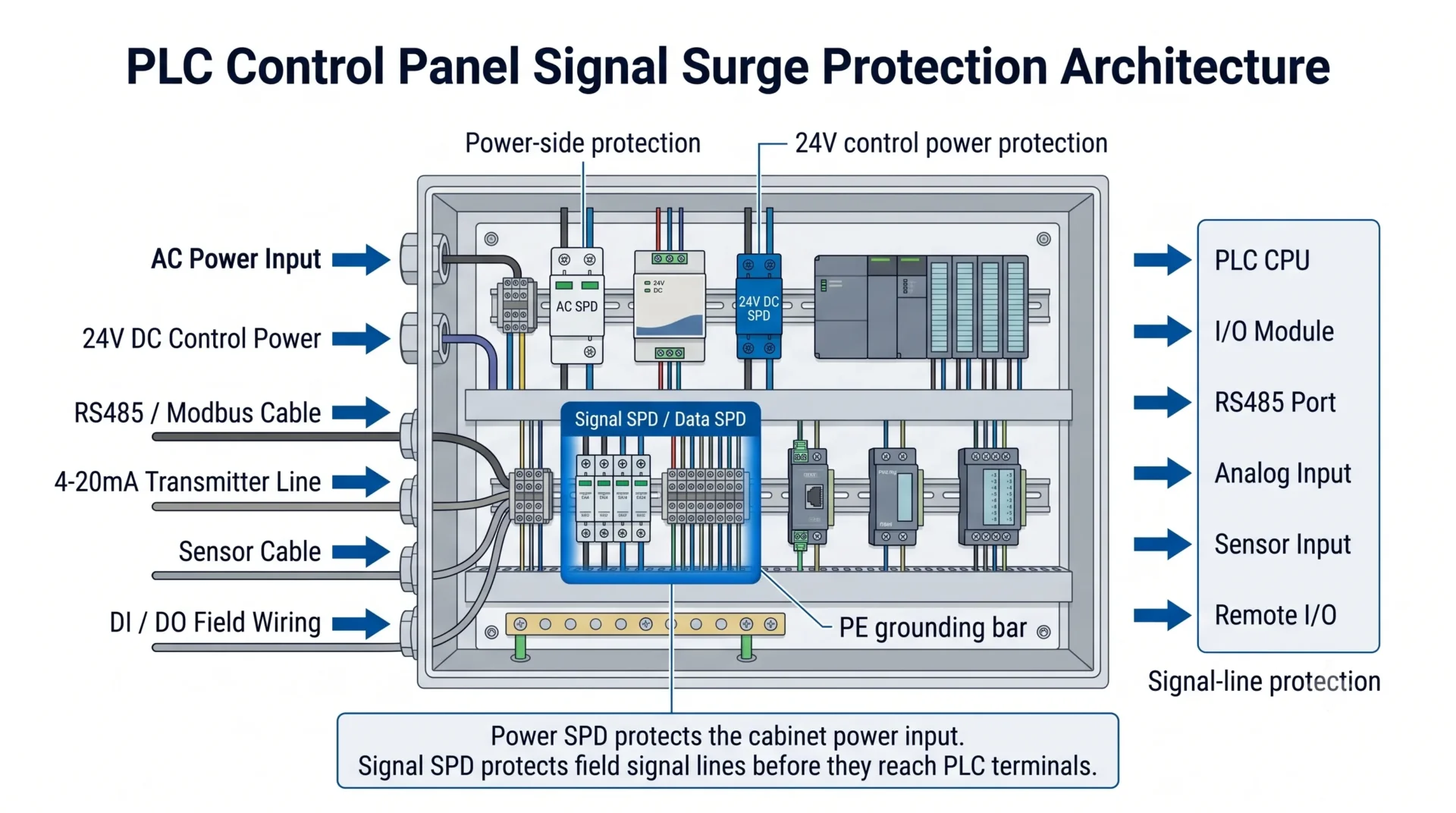
| PLC-Leitung | Typisches Beispiel | Wenn Signal-SPD empfohlen wird | Bedeutung für Käufer |
|---|---|---|---|
| DI \/ DO | 24V digitale Eingabe, Relaisausgang, Maschinenstatussignal | Lange Feldverkabelung, Außenanlagen, induktive Lasten, separate Maschinenabschnitte | Schützt PLC-I/O-Anschlüsse vor transienten Spannungen, die über Feldleitungen eindringen. |
| KI / AO | 0-10V, 4-20mA Sender-Schleife | Sensor oder Sender befindet sich außerhalb des Schaltschranks oder Kabel ist Störungen ausgesetzt | Hilft, Schäden und instabile Messwerte bei analogen Modulen zu reduzieren. |
| RS485 / Modbus-RTU | PLC zu Messgerät, Wechselrichter, Remote-I/O, SCADA-Gerät | Langes Buskabel, Außen-RS485, mehrere Schaltschränke, unterschiedliche Erdungszonen | Schützt Kommunikationsports, ohne einen AC-Power-SPD auf einer Datenleitung zu verwenden. |
| Sensorkabel | Proximitäts-Sensor, Drucksensor, Pegelsensor, Durchflussmessgerät | Sensorleitung verläuft entlang von Feldtrögen, in der Nähe von Motoren oder außerhalb des geschützten Schrankbereichs | Schützt den schwachen Signalweg, bevor er die PLC-Eingangsterminals erreicht. |
| Feldgerätekabel | Ventilantrieb, Pumpensignal, Status des entfernten Geräts | Kabel verbindet Geräte in einer anderen Zone, einem anderen Schrank oder im Freien | Reduziert das Risiko von Überspannungen durch Spannungsunterschiede im Erdpotential und induzierte Transienten. |
Warum PLC-Signalleitungen Überspannungsschutz benötigen
Ein PLC-Steuerungsfeld ist nicht nur durch sein eingehendes Stromkabel geschützt. Überspannungsenergie kann durch jeden leitenden Pfad, der mit dem PLC-System verbunden ist, eindringen.
Für industrielle Steuerfelder sind die häufigsten Pfade:
- AC-Eingangsversorgung zum Steuergehäuse.
- 24VDC-Steuerstrombus im Inneren des Schranks.
- PLC-I/O-Verkabelung, die mit Feldgeräten verbunden ist.
- RS485, Modbus RTU, Telemetrie und Fernüberwachungsleitungen.
- Sensor- und Instrumentenkabel, die außerhalb des Schaltschranks verlaufen.
Deshalb kann es erforderlich sein, dass ein Schrank sowohl Strom-SPDs als auch Signal-SPDs benötigt. Der Strom-SPD befasst sich mit Überspannungsenergie auf der Stromversorgungsseite. Der Signal- SPD befasst sich mit transienten Überspannungen auf der Niederspannungssteuerungs- oder Kommunikationsseite.
Wichtig: Ein AC- SPD schützt nicht jeden PLC-Anschluss.
Wenn ein 50-Meter-Sensorkabel in den Schrank gelangt und direkt mit einem PLC-Eingangsmodul verbunden ist, kann eine Überspannung, die auf diesem Kabel induziert wird, den PLC erreichen, bevor der AC- SPD irgendeine Chance hat zu helfen.
Aus diesem Grund sollten Signal-SPDs am Eintrittspunkt des Feldkabels in Betracht gezogen werden, insbesondere dort, wo die Kabel lang, im Freien, exponiert oder mit entfernten Geräten verbunden sind.
Überspannungsschutz für PLC I/O: Welche Leitungen benötigen Signal-SPD?
Nicht jedes kleine Signalkabel benötigt einen separaten SPD. Die richtige Entscheidung hängt von der Kabelführung, der Exposition, der Installationsumgebung, der Systembedeutung und der Projektspezifikation ab.
In der Regel schützenswert
- Außensensoren und -sender.
- RS485-Busleitungen zwischen Schaltschränken.
- Fern-I/O-Kabel.
- 4-20mA-Schleifen von Feldinstrumenten.
- Signalkabel in der Nähe von VFDs, Motoren, Pumpen oder langen Stromkabeln.
- Steuerleitungen, die aus einem anderen Gebäude oder einem anderen Erdungsbereich eingehen.
Benötigt möglicherweise nicht immer einen separaten SPD
- Sehr kurze interne Verkabelung innerhalb desselben Schaltschranks.
- PLC- und I/O-Modul in einem geschützten Gehäuse installiert.
- Kein Außenkabel und kein langer Feldkabelweg.
- Wertloses, nicht-kritisches Steuersignal.
- Die Projektspezifikation erfordert keinen Überspannungsschutz für Signalleitungen.
Für OEM-Steuerpanels ist der sicherste Ansatz, dies während der Planung zu bestätigen, anstatt bis zur Inbetriebnahme vor Ort zu warten. Wenn das Panel bereits verkabelt ist, kann das Hinzufügen von Signal-SPDs Änderungen am Anschlusslayout, Platz auf der DIN-Schiene, Überprüfung der Erdung und neue Verkabelungspläne erforderlich machen.
Benötigen Sie für jeden PLC I/O-Punkt Überspannungsschutz?
In der Regel nein. Die Installation eines SPDs an jedem einzelnen I/O-Punkt kann die Kosten, den Platz im Schrank, die Verkabelungszeit und die Wartungskomplexität erhöhen.
Eine bessere B2B-Auswahlmethode besteht darin, die I/O-Punkte nach Exposition zu gruppieren:
| I/O-Gruppe | Risikostufe | Praktische Empfehlung |
|---|---|---|
| Interne Schaltschranksignale | Niedrig | Verlassen sich in der Regel auf eine gute Erdung des Schranks, Kabeltrennung und Schutz auf der Stromseite. |
| Kurze, maschinenmontierte Sensoren | Mittel | Überprüfen Sie den Kabelweg, die Maschinenumgebung und die Kundenspezifikation. |
| Außensensoren oder lange Feldkabel | Hoch | Verwenden Sie ein Signal-SPD in der Nähe des Kabelanschlusses des Schranks oder vor dem PLC-Anschluss. |
| RS485 zwischen Schränken oder Gebäuden | Hoch | Verwenden Sie geeignetes RS485-/Daten-Signal-SPD und bestätigen Sie Spannung, Protokoll, Baudrate und Erdung. |
| Kritische Prozessmessung | Hoch | Schützen Sie analoge Schleifen- oder Übertragungssignale, bei denen Ausfallzeiten oder falsche Messwerte kostspielig sind. |
Einfache Regel für Schaltanlagenbauer
Wenn das Kabel im Schrank bleibt, ist das Risiko eines Überspannungsschadens normalerweise geringer. Wenn das Kabel den Schrank verlässt und ins Feld geht, behandeln Sie es als einen möglichen Eintrittsweg für Überspannungen.
Signal-SPD vs. SPD Fernalarmkontakt
Diese beiden Begriffe werden oft verwechselt, insbesondere in PLC-Schränken.
A Signal-SPD schützt eine Niederspannungs-Kommunikations- oder Steuerleitung, wie RS485, Sensorkabel oder einen industriellen Signalkreis.
Eine SPD-Fernalarmkontakt ist nur ein Statuskontakt an einem Strom-SPD. Er informiert die PLC, ob das SPD-Modul normal oder ausgefallen ist. Er schützt die PLC-Signalleitung selbst nicht.
| Artikel | Signal-SPD | SPD-Fernalarmkontakt |
|---|---|---|
| Hauptfunktion | Begrenzt die Überspannung auf einer Signal- oder Kommunikationsleitung. | Sendet den SPD-Status an PLC, BMS, SCADA, Lampe oder Alarmkreis. |
| Typische Anschlüsse | Eingangs- / Ausgangssignalanschlüsse, PE- oder Erdungsanschluss. | NO / NC / COM- Schaltkontakte. |
| Verwendet für | RS485, Sensorleitung, 4-20mA, Telemetrie, Fernsteuerungssignal. | Überwachung, ob eine AC- oder DC-SPD-Kartusche ausgefallen ist. |
| Kann es PLC I/O schützen? | Ja, wenn es korrekt ausgewählt und in der Signalleitung installiert ist. | Nein. Es berichtet nur den Status des SPD. |
Für Details zur Verdrahtung von Fernalarmsignalen siehe unser Handbuch: SPD-Fernalarmsignalverdrahtung zu PLC.
Auswahl von Signal-SPD für PLC DI/DO, AI/AO, RS485 und 4-20mA-Leitungen
Der richtige Signal-SPD wird durch den tatsächlichen Signalstrom ausgewählt, nicht durch die Gehäusegröße oder die AC-Systemspannung.
Bestätigen Sie den Signaltyp
Überprüfen Sie, ob die Leitung DI/DO, AI/AO, RS485, 4-20mA, Sensorsignal, Telemetrie, Fernsteuerung oder eine andere Niedervoltkabelleitung ist.
Abstimmen der Betriebsspannung
Die ausgewählte SPD-Spannung muss für die normale Signalspannung geeignet sein. Eine 5V-, 12V-, 24V- oder 48V-Signalleitung sollte nicht wie ein AC-Stromkreis behandelt werden.
Überprüfen Sie den Laststrom
Der Signal-SPD muss den normalen Strom des Stromkreises oder Signalstroms unterstützen. Dies ist besonders wichtig für analoge Schleifen und mit Strom versorgte Feldgeräte.
Überprüfen Sie die Übertragungsanforderung
Für RS485, Daten-, Telemetrie- oder Kommunikationsleitungen bestätigen Sie die Baudrate, Übertragungsdistanz, Kabeltyp und ob das SPD die Signalqualität beeinträchtigen kann.
Bestätigen Sie die Drahtanzahl und das Anschlusslayout
Überprüfen Sie, ob die geschützte Leitung 2-Draht, 3-Draht, 4-Draht, geschirmtes Paar oder Mehrdrahtkabel ist. Die SPD-Anschlussanordnung muss mit der Verkabelungsmethode übereinstimmen.
Planen Sie Erdung und Installationsposition
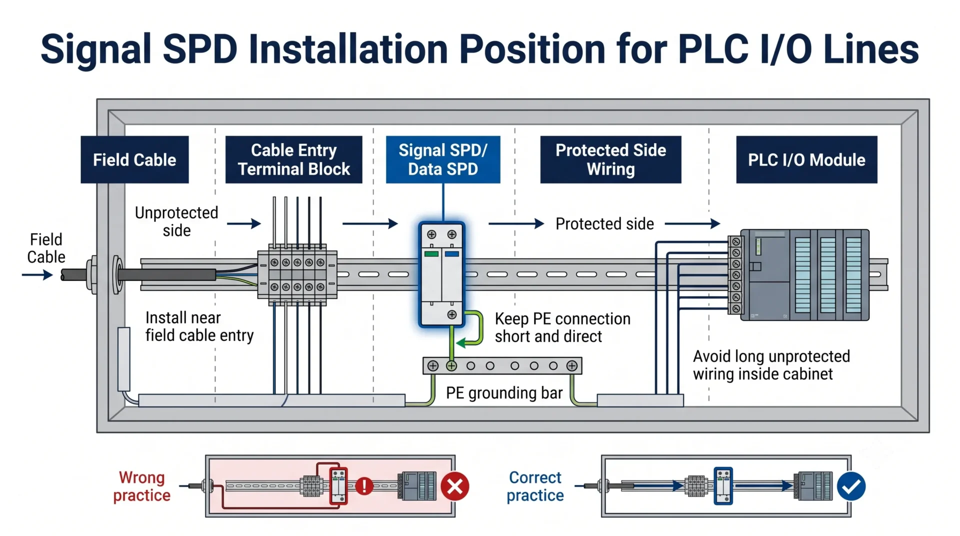
Installieren Sie die Signal-SPD in der Nähe des Punktes, an dem das Feldkabel in den Schrank eintritt. Halten Sie den Erdungsanschluss kurz und direkt. Vermeiden Sie es, ungeschirmte Feldkabel tief in den sauberen PLC-Verkabelungsbereich zu führen.
Empfohlene Auswahl nach PLC-Signaltyp
| Anmeldung | Was zu bestätigen ist | SPD-Auswahlrichtung |
|---|---|---|
| 24V Digitaleingang | Eingabetyp, Kabellänge, Feldspannung, gemeinsamer Bezug, Anschlusslayout | Verwenden Sie eine Signal-SPD, die für das 24V-Steuersignal ausgelegt ist und für die Feldverkabelung geeignet ist. |
| Digitalausgang / Relaisausgang | Lasttyp, Schaltfrequenz, induktive Last, Strom, Verdrahtungsweg | Bestätigen Sie, ob Überspannungsschutz in der Nähe der Last, am Schrankeingang oder beidem benötigt wird. |
| 4-20mA Analogschleife | Schleifen Spannung, Strom, Standort des Transmitters, Schleifen-Stromquelle, Erdungsmethode | Wählen Sie eine Signal-SPD aus, die die analoge Messung nicht stört und die Schleifen-Spannung unterstützt. |
| 0-10V analoges Signal | Signalspannung, Eingangsimpedanz, Kabelführung, Lärmeintrag | Verwenden Sie einen Niederspannungs-Schutz für signalgeschützte empfindliche analoge Eingänge. |
| RS485 / Modbus-RTU | Spannungsvariante, Baudrate, Kabellänge, Schirmerdung, Anzahl der Knoten | Verwenden Sie RS485 / Datensignal-SPD mit geeigneter Übertragungsleistung und geringem Einfügedämpfung. |
| Sensor / Feldinstrument | Sensor Spannung, Anzahl der Drähte, Ausgangstyp, Außenanwendung, Kabeltrassenverlauf | Wählen Sie gemäß Sensor-Spannung und Verdrahtungsmethode. Installieren Sie vor der SPS oder dem Signalmodul. |
PLC Signal SPD Parametermatrix
Diese Matrix hilft Käufern, den SPS-Signaltyp in praktische SPD-Auswahldetails zu übersetzen. Sie ersetzt kein Datenblatt, hilft jedoch, den häufigsten Fehler zu vermeiden: einen Signal-SPD nur nach Aussehen oder kA-Bewertung auszuwählen.
| Signalleitung | Übliche Spannung | Fokus der SPD-Auswahl | LEEYEE LY10 Richtung |
|---|---|---|---|
| RS485 / Modbus-RTU | Systemabhängig, oft Niederspannungs-Kommunikationsschaltung | Übertragungsrate, Einfügeverlust, Anschlusslayout, Erdung und Abschirmbehandlung | Bestätigen Sie die Version 12V / 24V / 48V gemäß der tatsächlichen Kommunikationsschaltung. |
| 24V DI / DO | 24V DC Steuersignal | Uc / MCOV über der normalen Steuerspannung, Laststrom, Verdrahtungsroute, Erdung | 24V Version mit 30V DC MCOV kann in Betracht gezogen werden, wenn der Stromkreis zu den Produktparametern passt. |
| 4-20mA Analogschleife | In der Regel wird es von einer 24V Schleifenversorgung betrieben | Schleifenspannung, Schleifenstrom, Messgenauigkeit, geringe Signalstörung | Bestätigen Sie zuerst die Schleifen- spannung und den Strom. Wählen Sie nicht nur nach dem Namen des PLC-Eingangsmoduls aus. |
| Sensorkabel | 12V / 24V / 48V je nach Sensortyp | Sensor Spannung, Drahtanzahl, Ausgabetyp, Kabelroute, Außeneinwirkung | Ordnen Sie die 12V / 24V / 48V Version dem tatsächlichen Sensorkreis zu. |
| Telemetrie / Fernsteuerung | 12V / 24V / 48V oder projektspezifisch | Protokoll, Kabellänge, Überspannungseinwirkung, Erdungszone, Anschlussanordnung | Stimmen Sie die Spannungs- und Protokollanforderung ab, bevor Sie das Modell bestätigen. |
Professionelle Grenze
LY10 ist hauptsächlich für RS485, Telemetrie, Fernsteuerung, Sensor und Niederspannungs-Industrietechnische Signalleitungen geeignet, wenn die Schaltung die Produktbewertung erfüllt.
Für Ethernet, PoE, Profibus, spezielle Hochgeschwindigkeits-Kommunikationsschnittstellen oder projektspezifische Bussysteme, bestätigen Sie den Schnittstellentyp und verwenden Sie stattdessen einen passenden Datenleitungs-SPD, anstatt anzunehmen, dass ein Modell für alle Signalleitungen geeignet ist.
Empfohlene LEEYEE Signal-SPD für PLC- und RS485-Leitungen
Für RS485, Telemetrie, Fernsteuerung, PLC, Sensor und industrielle Kommunikationsleitungen ist der LEEYEE LY10 ein Datenleitungs-Überspannungsschutz für die Hutschiene, der für Steuerungsschränke und industrielle Signal- schaltungen konzipiert ist.
Typische verfügbare Versionen umfassen 12V, 24V und 48V Signalsysteme. Das Produkt ist für die Hutschieneninstallation und die Serienverbindung vor empfindlichen Geräten konzipiert.
| Parameter | LY10 Auswahldaten |
|---|---|
| Produktart | RS485 / Daten-Signal-Überspannungsschutz |
| Nennbetriebsspannung | 12V / 24V / 48V DC |
| Maximale Dauerbetriebsspannung | 15V / 30V / 60V DC |
| Nennlaststrom | 500mA |
| Übertragungsrate | Bis zu 10Mbps |
| Einfügungsdämpfung | ≤ 0,2 dB |
| Einrichtung | 35mm DIN-Schiene / Anschlussklemme |
Wo sollte das Signal-SPD installiert werden?
Für PLC-Steuerkästen ist der beste praktische Standort normalerweise in der Nähe des Feldkabel-Einführungspunktes, bevor das Kabel den PLC-Anschluss oder Kommunikationsmodul erreicht.
Dies hilft, die Überspannung zu stoppen, bevor sie durch den sauberen Steuerverdrahtungsbereich im Gehäuse gelangt.
| Installationsposition | Empfohlen? | Grund |
|---|---|---|
| An der Feldkabeleingangsanschlussschnur | Beste Praxis | Unterbricht die Überspannung, bevor sie in den PLC-Verkabelungsbereich eintritt. |
| Direkt neben dem PLC-Modul | Manchmal akzeptabel | Besser als kein Schutz, aber ungeschützte Kabel könnten trotzdem im Gehäuse verlaufen. |
| Nur am Haupt-AC-Panel | Nicht ausreichend für Signalleitungen | AC SPD klemmt das Niederspannungssignal-Kabel, das in die PLC-Anschlüsse gelangt, nicht. |
| Nur an entfernten Feldgeräten | Hängt vom Layout ab | Kann das Feldgerät schützen, aber die PLC-Seite benötigt möglicherweise weiterhin Schutz, wenn das Kabel lang oder exponiert ist. |
Häufiger Fehler
Installieren Sie das Signal-SPD nicht weit entfernt von der geschützten Ausrüstung und führen Sie dann lange ungeschützte Signalkabel innerhalb des Schaltschrankes. Das Kabel zwischen dem Eintrittspunkt und der SPS kann immer noch Überspannungsenergie und Geräusche in den empfindlichen Bereich übertragen.
Was passiert, wenn PLC-Signalleitungen nicht geschützt sind?
Der Ausfall sieht möglicherweise nicht immer wie ein verbranntes Bauteil aus. An vielen industriellen Standorten erscheinen überschlagsbezogene Signalprobleme zunächst als instabile Kommunikation, zufällige Eingangsalarme, analoge Messabweichungen oder wiederholte Ausfälle desselben I/O-Kanals.
Mögliche Ergebnisse umfassen:
- Schaden am SPS-Kommunikationsanschluss.
- Verlust der RS485- oder Modbus-RTU-Kommunikation.
- Instabilität der analogen Eingangslesungen.
- Fehlalarm von Feldsensoren.
- Wiederholter Austausch von I/O-Modulen.
- Unerwarteter Maschinenstillstand oder Produktionsausfall.
- Schwer zu diagnostizierende intermittierende Fehler nach Stürmen oder Schaltvorgängen.
Für Wartungsteams im Werk sind diese Ausfälle teuer, da das beschädigte SPS-Modul nur einen Teil der Kosten ausmacht. Die höheren Kosten entstehen durch Fehlerbehebung, Stillstand der Linie, Notfallersatz und wiederholte Site-Besuche.
Vor der Bestellung von Signal-SPD für PLC-Module
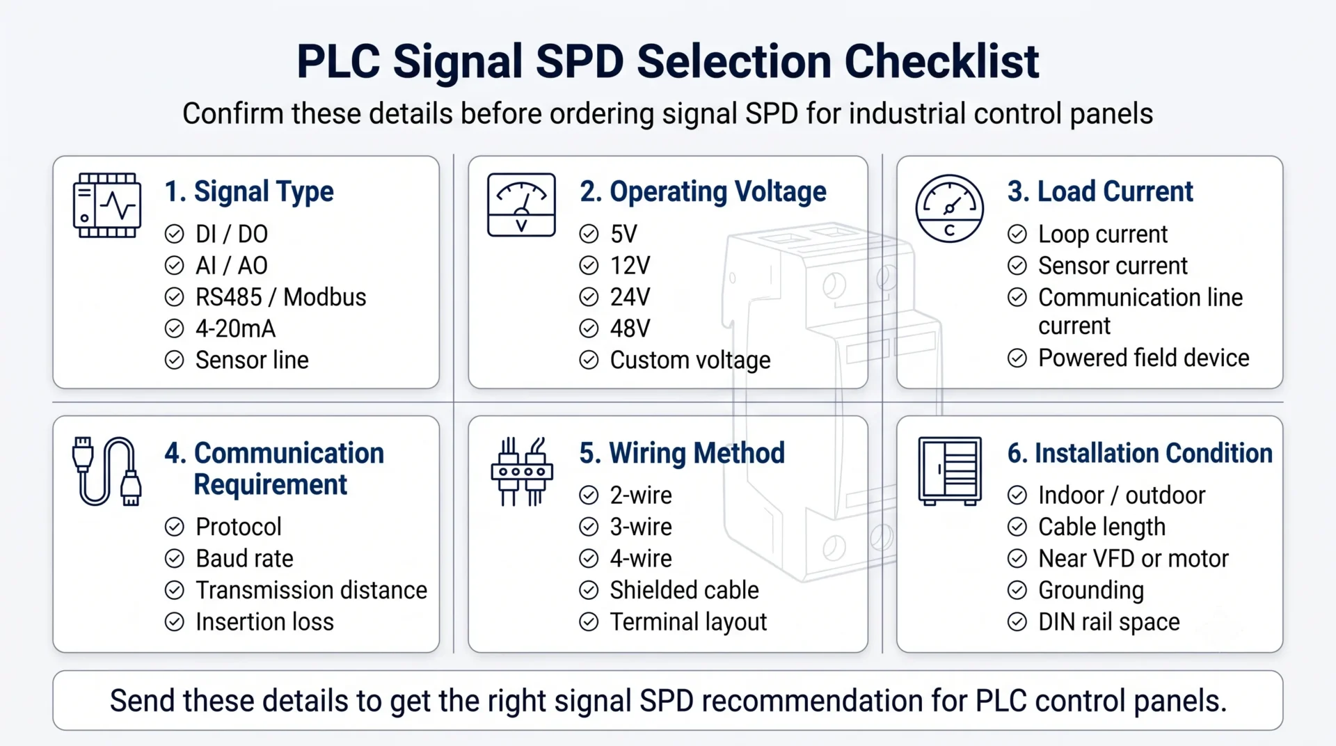
Diese Angaben für eine schnellere Modellauswahl senden
- Signaltyp: DI, DO, AI, AO, RS485, 4-20mA, Sensor, Telemetrie oder andere.
- Normale Betriebsspannung: 5V, 12V, 24V, 48V oder andere.
- Vom Projekt erforderliche maximale Dauerspannung.
- Laststrom oder Schleifenstrom.
- Protokoll und Baudrate für Kommunikationsleitungen.
- Anzahl der Adern und Klemmenanordnung.
- Kabelverlauf: innen, außen, zwischen Schaltschränken, zwischen Gebäuden oder in der Nähe von Stromkabeln.
- Erdungsmethode und Anforderung an die Schirmerdung.
- Einbauraum: Breite der DIN-Schiene, Klemmenanordnung, Schaltschranktiefe.
- Anforderungen an OEM-Kennzeichnung, Eigenmarke, Datenblatt, Verpackung oder Verdrahtungsplan.
Häufige Auswahlfehler
| Fehler | Warum dies ein Problem ist | Bessere Praxis |
|---|---|---|
| Verwendung eines AC-SPD an RS485- oder Signalleitung | Die Spannungsstufe und der Prüfnorm des AC-SPD sind für niederohmige Datenleitungen nicht geeignet. | Verwenden Sie einen auf den Kommunikations- oder Steuerkreis abgestimmten Signal-/Daten-SPD. |
| Auswahl nur nach kA-Nennwert | Die Auswahl des Signal-SPD hängt auch von Spannung, Strom, Übertragungsrate und Verdrahtungsmethode ab. | Bestätigen Sie den tatsächlichen Signalkreis, bevor Sie den SPD auswählen. |
| Einfügedämpfung oder Datenrate ignorieren | Das falsche SPD kann die Kommunikationsqualität an RS485- oder Datenleitungen beeinträchtigen. | Prüfen Sie Übertragungsrate, Einfügedämpfung, Baudrate und Kabellänge. |
| SPD ohne gute Erdung installieren | Schlechte Erdung begrenzt den Überspannungsableitpfad und verringert die Schutzwirkung. | Halten Sie die Erdung kurz, direkt und konsistent mit dem Erdungskonzept des Schranks. |
| Fernmeldekontakt mit Signal-SPD verwechseln | Der Fernmeldekontakt meldet nur den SPD-Status. Er schützt die Signalleitung nicht. | Verwenden Sie den Fernalarm für die Überwachung und das Signal-SPD für den Schutz der Signalleitung. |
| Nur eine Seite einer langen Außenleitung schützen | Lange Kabelstrecken können beide Enden der Ausrüstung einem Überspannungsrisiko aussetzen. | Prüfen Sie, ob sowohl die PLC-Seite als auch die Feldgeräteseite einen koordinierten Schutz benötigen. |
Verwandte Lektüre
Wenn Sie ein vollständiges industrielles Schaltschrank-System entwerfen, können Ihnen diese Seiten helfen, Anforderungen an Schutz auf der Leistungsseite, an der Signalseite und an die Überwachung zu trennen.
FAQ: PLC I/O Signal Überspannungsschutz
Benötigen PLC-Signalleitungen Überspannungsschutz?
PLC-Signalleitungen benötigen Überspannungsschutz, wenn sie mit Außensensoren, langen Feldkabeln, Remote-I/O, RS485-Netzwerken, Feldgeräten oder Geräten verbunden sind, die in einem anderen Schaltschrank oder Erdungsbereich installiert sind. Kurze interne Schaltschrankverdrahtung benötigt möglicherweise nicht immer einen separaten Signal-SPD.
Was ist der Unterschied zwischen Überspannungsschutz für PLC I/O und Überspannungsschutz für AC-Schaltschränke?
Der Überspannungsschutz für AC-Schaltschränke schützt die eingangsseitige Stromversorgung des Schaltschranks. Der Überspannungsschutz für PLC I/O schützt Niederspannungs-Signalwege wie Digital-Eingang, Analog-Eingang, RS485, 4-20mA-, Sensor- und Feldgeräteverdrahtung. Diese beiden Schutzpunkte dienen unterschiedlichen Stromkreisen.
Kann ein AC Typ 2 SPD die PLC I/O-Klemmen schützen?
Ein AC Typ 2 SPD schützt den Stromeingang des Schaltschranks. Er schützt Niederspannungs-Signalverdrahtung, die an PLC I/O- oder Kommunikationsklemmen angeschlossen ist, nicht direkt. Signalleitungen benötigen geeignete Signal-SPDs, wenn sie einem Überspannungsrisiko ausgesetzt sind.
Soll jeder PLC-Eingang und -Ausgang einen Überspannungsschutz haben?
Nicht immer. Ein praxisgerechter Entwurf schützt zuerst die besonders gefährdeten Leitungen: Außensensoren, lange Feldkabel, RS485-Busleitungen, entfernte I/O, Analogkreise und Kabel, die in der Nähe von Motoren oder VFDs verlaufen. Interne kurze Verdrahtung innerhalb desselben Schranks benötigt möglicherweise nicht an jedem Punkt einen eigenen SPD.
Kann ich einen Signal-SPD für mehrere PLC I/O-Leitungen verwenden?
Nur wenn die Auslegung des SPD, die Klemmenanordnung, die Nennspannung, die Strombelastbarkeit und die Verdrahtungsmethode für diese Leitungen geeignet sind. Unabhängige Signalarten sollten nicht blind zusammengeführt werden. RS485-, Analogkreis-, Digital-Eingangs- und Sensorleitungen können unterschiedliche Schutzanordnungen benötigen.
Welche Signalspannung für einen SPD sollte ich für einen 24V PLC-Eingang wählen?
Wählen Sie einen Signal-SPD, dessen Nennspannung und maximale dauerhafte Betriebsspannung für das normale 24V DC-Steuersignal geeignet sind. Beispielsweise kann ein 24V-Signal-SPD mit einer geeigneten MCOV oberhalb der normalen Betriebsspannung in Betracht gezogen werden, die endgültige Auswahl sollte jedoch auch Strom, Verdrahtungsmethode, Erdung und Projektanforderungen berücksichtigen.
Welcher SPD sollte für RS485 an einer PLC verwendet werden?
Verwenden Sie einen Daten- oder Signal-SPD, der für RS485 und ähnliche industrielle Kommunikationskreise ausgelegt ist. Bestätigen Sie vor der Bestellung Spannungsvariante, Baudrate, Übertragungsstrecke, Einfügedämpfung, Aderzahl, Schirmerdung und Einbauposition.
Kann ein Signal-SPD für 4-20mA-Analogkreise verwendet werden?
Ja, wenn der SPD für die Schleifenspannung, den Schleifenstrom, die Verdrahtungsmethode und die Anforderung an die Messgenauigkeit geeignet ist. Der SPD sollte das Analogsignal schützen, ohne den normalen 4-20mA-Betrieb zu beeinträchtigen.
Wo sollte ein Signal-SPD in einem PLC-Schrank installiert werden?
Installieren Sie ihn in der Nähe des Eintrittspunkts des Feldkabels oder der Klemmenreihe, bevor die Signalleitung das PLC-Modul erreicht. Halten Sie die Erdungsverbindung kurz und direkt, und vermeiden Sie lange ungeschützte Signalverdrahtung im sauberen Steuerungsbereich.
Ist ein Remote-Alarmkontakt eines SPD dasselbe wie ein Signal-Überspannungsschutz?
Nein. Ein Remote-Alarmkontakt ist ein potentialfreier Kontakt, der verwendet wird, um den SPD-Status an eine PLC, BMS, SCADA, eine Lampe oder einen Alarmschaltkreis zu melden. Ein Signal-SPD wird in der Signalleitung installiert, um die Überspannung zu begrenzen, bevor sie empfindliche Geräte erreicht.
Welche Informationen sollte ich senden, um einen PLC-Signal-SPD auszuwählen?
Senden Sie den Signaltyp, die Betriebsspannung, den Leitungsstrom, das Protokoll, die Baudrate, die Anzahl der Adern, den Kabelverlauf, die Erdungsmethode, den verfügbaren Einbauraum im Schaltschrank sowie alle Anforderungen an OEM-Kennzeichnung oder Verdrahtungsplan. So kann der Lieferant schneller ein geeignetes Signal-SPD-Modell empfehlen.
Hilfe bei der Auswahl von Signal-SPD für ein PLC-Steuerpaneel benötigt?
Senden Sie uns Ihren PLC-Signaltyp, die Spannung, den Kabelverlauf und den Schaltschrankaufbau. LEEYEE kann Ihnen helfen, einen geeigneten Signal-SPD für RS485-, Sensor-, Telemetrie-, Fernsteuerungs- und industrielle Kommunikationsleitungen zu empfehlen.
