
Ingénierie SPD, inspection de site et guide de sélection OEM
Une lecture de faible résistance à la terre est utile, mais elle ne prouve pas à elle seule qu'un SPD a un chemin de courant de surtension efficace. Les ingénieurs doivent également vérifier la continuité PE, l'impédance transitoire, le bond d'équipotentialité, le type de système de mise à la terre et la relation entre le SPD et l'équipement protégé.
Table des matières
Réponse rapide
Une résistance de mise à la terre élevée peut réduire la performance de protection installée d'un SPD en augmentant la tension transitoire le long de la terre, du PE et du chemin de liaison. Toutefois, il n'y a pas d'exigence universelle de 1Ω, 5Ω ou 10Ω pour chaque installation de SPD. La norme de projet applicable, le système de mise à la terre, la liaison équipotentielle et le chemin de courant de surtension complet doivent tous être vérifiés.
Le SPD peut fonctionner normalement alors que l'équipement protégé subit toujours une tension excessive causée par l'impédance des conducteurs ou une différence de potentiel transitoire entre des références de mise à la terre séparées.
Une bonne protection SPD nécessite un chemin de courant coordonné, court et à faible impédance – pas seulement une lecture basse sur un testeur de résistance à la terre.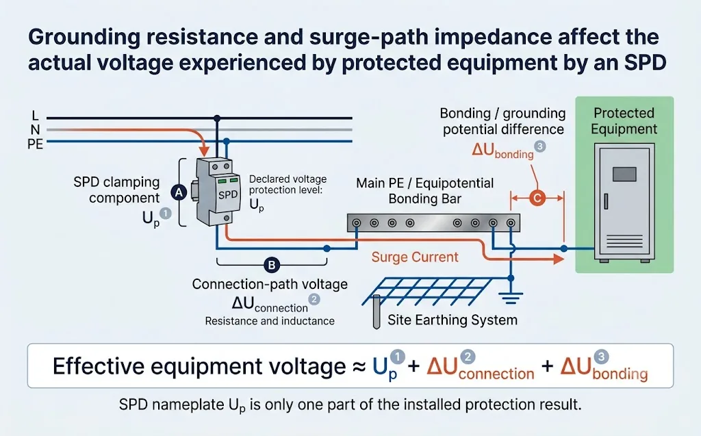
Un SPD peut-il fonctionner sans mise à la terre ?
La réponse techniquement correcte est : cela dépend du mode de protection SPD et de la conception du système.
Un SPD limite la tension entre les conducteurs connectés à ses bornes. Un mode de protection entre la phase et le neutre peut limiter une surtension en mode différentiel sans utiliser un électrode de terre local comme chemin de courant direct. En revanche, L–PE, N–PE, positif–PE, négatif–PE et de nombreux modes de protection signal-terre dépendent fortement d'une connexion PE ou de liaison équipotentielle correcte.
| Mode de protection | Dépendance au PE ou à la terre | Signification technique |
|---|---|---|
| L–N ou pôle à pôle | Peut limiter la tension en mode différentiel entre les deux conducteurs conducteurs de courant connectés. | Cela ne prouve pas que la protection en mode commun ou l'installation complète est sûre sans PE. |
| L–PE ou pôle à PE | Nécessite un chemin de protection à terre ou de liaison équipotentielle approprié. | Une connexion PE manquante, lâche ou à haute impédance peut réduire sérieusement le résultat de protection installé. |
| N–PE | Dépend du chemin de protection neutre-terre défini par le système de mise à la terre et la topologie SPD. | Particulièrement important dans de nombreux systèmes TT 1+1 et 3+1. |
| Signal à la terre ou blindage | Nécessite un raccordement de référence coordonné entre le SPD de signal, l'équipement et l'écran de câble. | Des références de terre séparées peuvent forcer le courant à travers les ports de communication ou l'isolation de l'équipement. |
Même lorsque l'un des modes de protection différentielle peut conduire, l'installation peut toujours manquer de protection en mode commun sûr, de liaison de protection ou de la connexion requise par le fabricant du SPD. Suivez toujours le schéma de câblage et le design électrique applicable.
Pourquoi la mise à la terre est-elle importante pour un SPD ?
Lorsque un transient dépasse le seuil de fonctionnement du SPD, le SPD passe à un état conducteur et crée un chemin à faible impédance entre ses bornes connectées. Le courant de surtension suit alors le chemin du système électrique à travers les conducteurs sous tension, le neutre, le PE, les conducteurs de liaison, les écrans de câbles, le métal structurel ou le système de mise à la terre.
L'objectif n'est pas simplement d“” envoyer toute l'énergie de surtension dans le sol. » L'objectif plus important est de maintenir l'équipement connecté et les systèmes conducteurs à des potentiels relatifs contrôlés pendant l'événement de surtension.
Quatre termes de mise à la terre qui ne doivent pas être considérés comme la même chose
Résistance de l'électrode de terre
La résistance mesurée entre un système d'électrode de terre et le sol environnant selon la méthode de test sélectionnée.
Continuité PE
Si la borne de terre SPD, l'armoire, la barre PE et la borne de mise à la terre principale ont une connexion métallique continue et mécaniquement fiable.
Impedance du chemin de surtension
L'opposition transitoire créée par la résistance, l'inductance, la géométrie du conducteur, les joints, le routage et le réseau de liaison plus large.
Liaison équipotentielle
La connexion coordonnée des systèmes conducteurs pour réduire les différences de tension dangereuses pendant les événements de défaut, d'orage et de surtension.
Un site peut montrer une résistance d'électrode de terre relativement basse mais avoir tout de même de mauvaises performances de SPD en raison d'un long chemin PE, d'un joint corrodé, d'un réseau de terre isolé ou d'une grande séparation entre le point de référence SPD et l'équipement protégé.
Que se passe-t-il lorsque la résistance de mise à la terre ou l'impédance du chemin sont trop élevées ?
| Problème potentiel | Que se passe-t-il lors d'une surtension | Conséquence possible du projet |
|---|---|---|
| Tension de chemin plus élevée | Le courant de surtension passant par la résistance et l'inductance crée une tension transitoire supplémentaire le long du chemin de courant. | L'équipement peut subir une tension supérieure à celle que le SPD a déclarée. Le seul Up pourrait le suggérer. |
| Élévation de potentiel de terre | Le courant entrant dans un système de mise à terre élève son potentiel local par rapport à d'autres points de référence. | Le courant peut circuler à travers des câbles de données, des écrans, des tuyaux ou un autre réseau de mise à terre de structure. |
| Différentes références d'équipement | Le SPD et l'équipement protégé ne s'élèvent pas au même potentiel transitoire en même temps. | Une tension dommageable peut apparaître aux bornes de l'équipement, des ports de communication ou de l'isolation. |
| Chemin de courant non intentionnel | La surtension utilise un chemin parallèle avec une impédance transitoire inférieure à celle de la voie de liaison prévue. | Les écrans de câble, l'I/O PLC, RS485, Ethernet ou les ports de communication de l'onduleur peuvent transporter une partie du courant. |
| Échec de la coordination de protection | Les SPDs de puissance et de signal font référence à différents points de terre ou de liaison. | Différents circuits connectés au même appareil peuvent être limités à différents potentiels transitoires. |
Le problème principal n'est normalement pas un fonctionnement interne du SPD plus lent. Le problème réside dans une tension supplémentaire à l'extérieur du SPD, le long des conducteurs et entre différentes références de mise à terre.
Résistance de mise à la terre vs impédance du chemin de surtension
Un test normal de résistance de terre fournit des informations utiles sur le système d'électrode de terre dans les conditions de test choisies. La foudre et les courants de surtension, cependant, peuvent augmenter très rapidement. Pendant ces événements transitoires, l'inductance des conducteurs, les courbures, les boucles, l'espacement et la géométrie de mise à terre peuvent devenir des parties majeures de l'impédance du chemin de courant.
Gardez la boucle de courant de surtension compacte, utilisez le point de liaison équipotentielle prévu, évitez les systèmes de référence non coordonnés et protégez tous les services conducteurs entrant dans la zone protégée.
Un SPD nécessite-t-il une résistance de mise à la terre de 1Ω, 5Ω ou 10Ω ?
Il n'y a pas de limite de résistance universelle uniquement pour le SPD qui s'applique à chaque installation. Une exigence numérique peut provenir d'un code électrique national, d'une conception de protection contre la foudre, d'une règle de service public, d'une spécification d'opérateur télécom, d'un propriétaire de projet, d'un assureur ou d'un fabricant d'équipement.
Le résultat mesuré doit donc être comparé à un document gouvernant clairement identifié, et non copié d'un article générique en ligne.
| Situation du projet | Comment traiter la valeur en Ohm | Ce qui doit également être vérifié |
|---|---|---|
| Bâtiment LV général | Suivez les exigences locales de sécurité électrique et de mise à la terre. Ne pas inventer une limite SPD séparée sans une base définie. | Terminal de mise à la terre principal, continuité PE, liaison, emplacement SPD, mode de protection et cheminement des conducteurs. |
| Installation photovoltaïque en champ libre | Utilisez le design photovoltaïque et de protection contre la foudre du projet, y compris ses critères d'acceptation de grille de terre spécifiés. | Réseau de terre maillé, structures interconnectées, stations d'onduleurs, chemins de câbles, conditions de corrosion et saisonnières. |
| Site de télécommunications ou tour | Utilisez la spécification de mise à la terre de l'opérateur et le design de protection contre la foudre du site. | Tour, armoire, SPD AC, SPD DC, SPD de données, alimentation d'antenne, écrans et barrette de terre commune. |
| Installation critique | Traitez la valeur comme une exigence de conception système complète, pas comme un paramètre de produit SPD universel. | Géométrie de la grille de terre, tension de contact et de pas, courant de défaut et coordination de protection. |
| Tableau de distribution OEM | Le constructeur de panneaux ne peut pas déterminer la résistance à la terre finale du site uniquement à partir du modèle SPD ou du dessin du panneau. | Terminaux PE corrects, exigences des conducteurs, schéma d'installation et instructions de mise en service sur site. |
Un site peut montrer un résultat d'électrode satisfaisant tandis que le SPD est connecté par un long conducteur, une jointure corrodée ou une référence séparée de l'équipement protégé. Le chemin complet doit être inspecté.
Comment la résistance de mise à la terre d'un SPD doit-elle être mesurée ?
Il n'existe pas d'instrument spécial mesurant une “résistance de mise à la terre SPD” universelle. La méthode de test dépend de si l'ingénieur doit évaluer une électrode de terre, un branche d'un réseau de mise à la terre parallèle, une boucle de terre complète ou seulement la continuité du conducteur PE local.
| Méthode de test | Utilisation typique | Limitations principales | Ce que l'acheteur devrait demander |
|---|---|---|---|
| Chute de potentiel à 3 points | Test d'une électrode de terre ou d'un système d'électrode en utilisant des piquets de test de courant et de potentiel séparés. | Nécessite une distance de test suffisante et un accès au sol approprié. Des chemins parallèles peuvent devoir être pris en compte ou isolés. | Électrode testée, positions des sondes, courbe de test ou points de validation, résultat mesuré et conditions du site. |
| Test de terre sélectif | Mesurer une section d'un système de mise à la terre parallèle en utilisant des piquets de test plus un collier de courant. | Le testeur doit comprendre le réseau parallèle et placer le collier sur le bon conducteur. | Branche mesurée, diagramme du réseau, position du collier, disposition des piquets de test et résultat. |
| Test à pince ou sans piquet | Test rapide où plusieurs chemins de mise à la terre créent une boucle conductive complète. | Il n'est pas adapté à chaque électrode simple isolée car une boucle de retour valide est requise. | Confirmation qu'une boucle parallèle fermée existe et explication de quelle résistance l'instrument a mesurée. |
| Test de continuité PE | Vérification si la borne de terre de l'SPD est continuellement connectée à la barre PE ou au point de liaison principal. | Ne mesure pas la résistance de l'électrode de terre ou ne prouve pas une faible impédance haute fréquence. | Points de test, identification des conducteurs, continuité mesurée et inspection des bornes et des joints. |
| Inspection visuelle et de couple | Détection des bornes lâches, corrosion, conducteurs cassés, boucles nettes et connexions de référence incorrectes. | Ne peut pas remplacer une mesure électrique. | Photographies, taille du conducteur, itinéraire, condition du terminal et dossier de mise en service. |
Dossier de mesure minimum pour une équipe EPC ou de maintenance
- Électrode exacte, grille ou conducteur testé
- Modèle de l'instrument et état de calibration
- Méthode de test utilisée
- Positions de la sonde ou du serre-câble
- Valeur mesurée et unité
- Si des chemins parallèles étaient connectés
- Condition du sol et météorologique
- Date du test et condition saisonnière
- Limite d'acceptation applicable
- Nom ou fonction du testeur qualifié
- Photographies des points de connexion
- Mesure corrective et résultat du nouveau test
Un multimètre peut aider à identifier une connexion ouverte ou manifestement défectueuse, mais il ne peut pas remplacer un testeur de terre approprié ni démontrer l'impédance transitoire complète du chemin de courant du SPD.
Que faire si la résistance de mise à la terre est trop élevée ?
L’action corrective doit traiter la cause du résultat et l’ensemble du système de protection. Remplacer le SPD par un modèle à kA plus élevé ne répare pas une mauvaise mise à la terre ou un réseau d’équipotentialité défectueux.
- Vérifier la mesure Confirmer que la méthode est adaptée à la configuration de l’électrode et que les chemins parallèles, l’espacement des sondes et les conditions saisonnières ont été pris en compte.
- Inspecter les connexions accessibles Vérifier les pinces, cosses, barres, points d’accès aux jonctions enterrées et conducteurs afin de détecter tout desserrage, corrosion, rupture, humidité ou dommage mécanique.
- Réparer les jonctions défectueuses Rétablir le chemin conducteur prévu à l’aide de matériaux appropriés, de méthodes de connexion adaptées et d’une protection contre la corrosion.
- Examiner la conception de l’électrode Un ingénieur qualifié peut devoir modifier la profondeur, l’espacement, le nombre d’électrodes, les conducteurs annulaires ou la conception du réseau de terre du site.
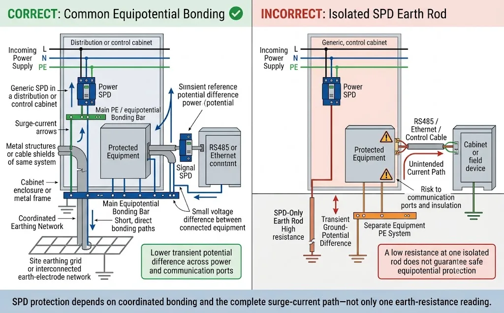
- Interconnecter les systèmes lorsque cela est requis Évitez d'ajouter une prise de terre dédiée uniquement au SPD, non reliée. Les structures et services séparés doivent être coordonnés conformément à la conception du projet.
- Améliorer les raccordements locaux du SPD Maintenez les raccordements aux conducteurs actifs et à la barre PE ou de liaison courts, directs et exempts de boucles inutiles.
- Coordonner la protection de l'alimentation et des signaux Vérifiez les circuits AC, DC, RS485, Ethernet, coaxiaux, les blindages et les services métalliques afin qu'aucun chemin non protégé ne fasse pont entre deux potentiels transitoires.
- Refaire les essais et documenter Consignez l'action corrective, répétez le test approprié et mettez à jour le plan tel que construit ainsi que le dossier de maintenance.
Une électrode isolée non coordonnée peut créer une différence de tension transitoire dangereuse entre le SPD, la PE de l'équipement et les systèmes de communication. Une faible valeur sur une seule prise de terre isolée ne garantit pas une protection équipotentielle sûre.
Comment le type de système de mise à la terre change l'évaluation du SPD
| Système | Chemin SPD pertinent | Vérification de la mise à la terre et des liaisons équipotentielles |
|---|---|---|
| TN-S | Chemins L–PE, N–PE ou L–N selon la topologie du SPD. | Confirmez que le SPD est raccordé à la barre PE du tableau et au réseau PE métallique commun par un chemin court et direct. Le résultat de l’électrode locale seul peut ne pas décrire ce chemin. |
| TT | Généralement une protection L–N plus un chemin N–PE coordonné dans une configuration 1+1 ou 3+1. | Confirmez l’électrode de terre de l’installation, la configuration du DDR, le mode de protection N–PE et les exigences locales. Ne créez pas de liaison N–PE aval non autorisée. |
| TN-C-S | Dépend du fait que le SPD soit positionné avant ou après la séparation du PEN. | Identifiez le point de séparation du PEN. En aval, N et PE doivent être traités conformément à la conception de l’installation et aux règles locales. |
| TN-C | Les conducteurs de phase peuvent être protégés contre le PEN au point applicable. | Confirmez la position d’installation autorisée et la configuration des conducteurs. Ne présumez pas qu’un N et un PE distincts existent à ce point. |
| TI | Configuration spécifique au projet phase-terre ou pôle-terre. | Confirmez la tension du système par rapport à la terre, le comportement au premier défaut, la surveillance de l’isolement, les exigences relatives à l’équipement et un Uc de SPD adapté. |
Pour des conseils supplémentaires sur la topologie, consultez le Guide de câblage du SPD triphasé et le Guide SPD 3P+N vs SPD 4P .
Contrôles de mise à la terre pour les projets solaires, de télécommunications et industriels
Systèmes photovoltaïques
- Confirmez si un système externe de protection contre la foudre existe.
- Vérifiez la liaison équipotentielle du cadre des modules et des rails de montage.
- Identifiez les réseaux de terre du champ, de l’onduleur et du bâtiment.
- Examinez les points d’entrée des câbles DC, AC et de communication.
- Vérifiez la corrosion et les variations saisonnières du sol.
- Confirmez si les structures séparées sont correctement interconnectées.
Télécommunications et stations de base
- Protection pour courant alternatif, courant continu −48 V, données et lignes d'antenne.
- Inspecter la mise à la terre du pylône, de l'armoire et du blindage des câbles d'alimentation.
- Raccorder les parafoudres de puissance et de signal à la référence prévue.
- Vérifier l'absence de corrosion et d'infiltration d'eau au niveau des joints externes.
- Vérifiez les niveaux de liaison séparés pour l'intérieur et l'extérieur.
- Respectez les spécifications de mise à la terre de l'opérateur télécom.
Armoires industrielles et extérieures
- Vérifiez les chemins de câbles d'alimentation et de signalisation de terrain entrants.
- Relier les boîtiers, les portes et les plaques de presse-étoupe si nécessaire.
- Séparer les conducteurs protégés des conducteurs non protégés.
- Vérifier les interfaces API, variateur de fréquence, RS485 et Ethernet.
- Inspecter le couple de serrage des bornes, les cosses et le cheminement des conducteurs.
- Identifiez les structures à proximité en utilisant une autre référence de terre.
Lorsque deux bâtiments, champs photovoltaïques, armoires ou instruments de terrain sont reliés par des câbles en cuivre mais utilisent des réseaux de terre distincts, la foudre peut créer une différence de potentiel importante entre eux. La protection de l'alimentation et des signaux doit être coordonnée aux limites des zones concernées.
Informations que les acheteurs doivent fournir avant de commander un SPD
Un fournisseur de parafoudres ne peut pas déterminer la conception complète de la mise à la terre uniquement à partir de la tension du système et de la valeur en kA. Les EPC, les tableautiers et les acheteurs de projets doivent fournir les informations sur le site ci-dessous avant la confirmation finale du produit.
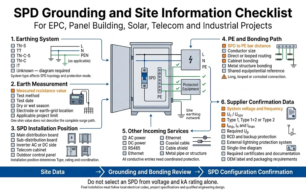
- Pays et norme de projet applicable
- Tension et fréquence du système
- Exigence de protection CA, CC, signal ou combinée
- Système TN-S, TT, TN-C-S, TN-C ou IT
- Schéma unifilaire indiquant N, PE et PEN
- Position d'installation du SPD
- Tableau principal, tableau divisionnaire, coffret de regroupement ou armoire de commande
- Système de protection contre la foudre externe : oui ou non
- Alimentation entrante aérienne ou souterraine
- Résistance de terre mesurée et méthode d'essai
- Date de mesure et conditions saisonnières
- Nombre et emplacement des électrodes ou des grilles
- Utilisation de réseaux de terre distincts pour les structures
- Distance entre le parafoudre et l'équipement protégé
- Distance entre le parafoudre et le conducteur de protection (PE) ou la barre d'équipotentialité
- Type 1, Type 1+2 ou Type 2 requis
- Uc, Ucpv, Up, In, Imax et Iimp requis
- Agencement du DDR et de la protection de secours
- Points d'entrée des câbles d'alimentation et de communication
- Exigence de contact de signal à distance
- Certificats et documentation requis
- Exigences relatives à l'étiquetage, à la couleur et à l'emballage OEM
« Nous avons besoin d'un parafoudre pour une armoire de distribution extérieure triphasée 400 V. Système de mise à la terre : TT. La résistance de terre mesurée est de 12 Ω selon la méthode de chute de potentiel. Le site est équipé d'un système de protection contre la foudre externe et d'un DDR. La connexion entre le parafoudre et la barre de terre est d'environ 300 mm. Veuillez confirmer la configuration de type 1+2 appropriée, le mode de protection N-PE, Uc, Iimp, la protection de secours et le schéma de câblage. »
Erreurs courantes de mise à la terre des SPD
| Erreur | Pourquoi c'est risqué | Meilleure approche |
|---|---|---|
| Utilisation d'un piquet de terre isolé uniquement pour le parafoudre | Cela peut créer une différence de potentiel importante entre le parafoudre, la terre de l'équipement et les autres services conducteurs. | Utilisez la conception coordonnée de mise à la terre et de liaison équipotentielle du projet, sauf si une conception qualifiée exige explicitement une autre disposition. |
| Acceptation du site sur la base d'une lecture d'un ohm | La lecture ne révèle pas de longs conducteurs, une géométrie médiocre, une séparation de référence ou des services non protégés. | Combinez la mesure, l'examen des plans, l'inspection visuelle et la vérification du chemin de courant. |
| Augmentation de la valeur nominale kA du parafoudre pour compensation | Une valeur Imax ou Iimp plus élevée ne supprime pas la tension développée le long d'une connexion défectueuse ou d'un réseau de liaison équipotentielle isolé. | Corrigez le système de mise à la terre et de liaison, puis sélectionnez le parafoudre en fonction de l'exposition réelle et du point d'installation. |
| Connexion en guirlande de plusieurs mises à la terre de parafoudres | La longueur de connexion partagée peut ajouter de l'impédance et permettre au courant d'un parafoudre d'affecter un autre circuit. | Raccordez chaque parafoudre au point de liaison équipotentielle prévu en utilisant la configuration approuvée pour le projet. |
| Ignorer les lignes de communication | Les câbles de données peuvent devenir le chemin de circulation du courant entre des équipements situés à des potentiels transitoires différents. | Coordonnez les parafoudres de puissance et de signal à la même limite de zone de protection et à la même référence de liaison équipotentielle. |
| Considérer toute valeur supérieure à 10 Ω comme une défaillance du parafoudre | Cela applique un chiffre générique sans tenir compte de la norme en vigueur, du système de mise à la terre ou du chemin de courant complet. | Comparez le résultat avec les exigences du projet et inspectez l'ensemble du système de protection contre les transitoires. |
En quoi cela est-il différent de la règle de longueur de connexion de 0,5 m pour le SPD ?
Sujet : Longueur de raccordement de 0,5 m
Se concentre sur les conducteurs locaux situés entre l'alimentation, le parafoudre (SPD) et le point de mise à la terre (PE) ou le point de liaison à l'intérieur du tableau de distribution.
L'objectif principal est de limiter la tension inductive supplémentaire causée par des câbles de raccordement de parafoudre inutilement longs.
Sujet : Résistance de mise à la terre
Se concentre sur le réseau plus large de liaison équipotentielle, de mise à la terre et de prise de terre au-delà des bornes du parafoudre.
Son objectif principal est de déterminer si le parafoudre et l'équipement protégé partagent une référence coordonnée et un chemin complet pour le courant de foudre.
Un câble de parafoudre court ne peut pas compenser un réseau de mise à la terre mal séparé. Une faible valeur de résistance de terre ne peut pas annuler la tension induite par une connexion de parafoudre inutilement longue.
Questions fréquemment posées
Un DPA fonctionne-t-il si la résistance de mise à la terre est élevée ?
Le parafoudre peut encore être conducteur, mais l'installation pourrait ne pas atteindre le niveau de protection escompté. La résistance et l'impédance transitoire peuvent générer une tension supplémentaire en dehors du parafoudre.
Un SPD peut-il fonctionner sans connexion à la terre ?
Certains modes de protection phase-neutre peuvent limiter la tension différentielle, mais les modes de protection utilisant la terre ou le conducteur de protection (PE) ne disposeront pas du chemin requis. Une installation dépourvue de la connexion PE nécessaire ne doit pas être considérée comme entièrement ou sûrement protégée.
Une valeur de 10Ω est-elle obligatoire pour chaque installation de parafoudre ?
Non. Une valeur de 10Ω peut figurer dans un projet spécifique ou dans une spécification de mise à la terre, mais il ne s'agit pas d'une exigence universelle propre aux parafoudres pour chaque pays et chaque installation.
Une résistance de mise à la terre plus faible est-elle toujours préférable ?
Une résistance d'électrode plus faible est généralement avantageuse, mais elle ne remplace pas une liaison équipotentielle correcte, des conducteurs courts, une géométrie appropriée et un placement coordonné des parafoudres.
Quelle est la meilleure méthode pour mesurer la résistance du sol ?
Il n'existe pas de méthode universelle adaptée à chaque site. La méthode de chute de potentiel est largement utilisée pour tester les électrodes, tandis que les méthodes sélectives et par pince peuvent s'avérer utiles en présence de chemins parallèles. L'opérateur doit choisir une méthode adaptée au réseau de mise à la terre réel.
Un multimètre peut-il tester une tige de terre isolée ?
Un contrôleur de terre à pince nécessite normalement une boucle de retour conductrice complète. Il peut ne pas fournir de résultat valide pour une électrode isolée sans autre chemin de mise à la terre parallèle.
Un SPD peut-il utiliser une tige de terre dédiée séparée ?
Un piquet de terre non relié séparé peut engendrer des différences de potentiel dangereuses. Le parafoudre doit normalement être intégré à la conception coordonnée de la mise à la terre et de la liaison équipotentielle.
Un SPD à haute kA résout-il un mauvais mise à la terre ?
Non. Un courant de décharge nominal plus élevé ne supprime pas les tensions créées par un mauvais acheminement des conducteurs, des joints corrodés, des références séparées ou un réseau de terre inadéquat.
Pourquoi l'équipement peut-il échouer alors que l'indicateur SPD est vert ?
Un indicateur vert indique normalement que le module de protection contre les surtensions n'a pas atteint sa fin de vie interne. Il ne confirme pas une mise à la terre, une longueur de conducteur, une liaison ou une coordination de protection correctes.
Quelles informations de mise à la terre un EPC doit-il transmettre au fournisseur de parafoudres ?
Veuillez transmettre le type de système de mise à la terre, le schéma unifilaire, la résistance mesurée, la méthode de test, les informations sur le système de protection contre la foudre externe (LPS), l'emplacement du parafoudre (SPD), les distances par rapport à la barre de terre (PE) et aux équipements, les tracés des câbles d'arrivée ainsi que les spécifications techniques du projet.
Confirmer le SPD et le chemin de mise à la terre avant de commander en vrac
Veuillez envoyer à LEEYEE votre schéma unifilaire, le type de système de mise à la terre, le rapport d'essai sur site, l'emplacement d'installation du parafoudre (SPD) et les exigences du projet. Nous vous aiderons à confirmer la configuration appropriée des parafoudres AC, DC ou de signal pour vos projets industriels, solaires, de télécommunications ou vos tableaux électriques.
Références autorisées
- DEHN, FAQ sur les systèmes d'alimentation électrique . Explique qu'aucune valeur spécifique de résistance de terre n'est requise pour chaque installation de parafoudre et souligne l'importance de la liaison équipotentielle.
- Institut NEMA de protection contre les surtensions, Mise à la terre et liaison . Traite des chemins à faible résistance et à faible impédance, des conducteurs de mise à la terre courts et directs pour parafoudres, ainsi que de l'auto-inductance des conducteurs.
- DEHN, Systèmes de protection contre la foudre et liaison équipotentielle . Explique l'utilisation de la liaison équipotentielle de foudre pour réduire les différences de potentiel causées par le courant de foudre.
- Fluke, Quatre méthodes pour effectuer des tests de mise à la terre . Présente les méthodes de chute de potentiel, sélective, sans piquet et autres méthodes connexes de test de terre.
- Fluke, Mesure de la chute de potentiel . Décrit le positionnement des sondes et les considérations de validation pour les tests de chute de potentiel.
- Megger, Test de terre par pince . Explique que le test par pince nécessite une boucle conductrice complète.
- Megger, Guide du test de terre . Couvre les essais d'électrodes par chute de potentiel et les contrôles périodiques des systèmes de mise à la terre.
- DEHN, Protection contre la foudre et les surtensions pour les parcs solaires . Traite des surfaces équipotentielles locales et distantes dans les systèmes photovoltaïques en champ libre.
