
Sélection d'un Parafoudre DC pour BESS n’est pas la même chose que de sélectionner un SPD PV solaire. Le circuit de batterie peut présenter différentes conditions de courant de défaut, de mise à la terre et de fin de vie. Le bon dispositif doit être sélectionné en fonction de l’enveloppe de fonctionnement réelle de la batterie, de l’interface PCS, des modes de protection, du courant de court-circuit prospective et de la position d’installation—et non uniquement à partir des mots “1000 V” ou “1500 V”.
Pour sélectionner un SPD BESS DC, confirmez d'abord le tension continue maximale de la batterie, et non seulement la tension nominale. Ensuite, confirmez l'arrangement de mise à la terre DC, les modes de protection requis, le courant de court-circuit attendu, la protection de secours, la tension d'impulsion de l'équipement et si le cabinet de batterie, le combiné DC et le PCS sont situés dans la même zone de protection contre la foudre.
Pour un circuit de batterie non PV, demandez une preuve appropriée de IEC 61643-41:2025 ou une autre base de test BESS DC approuvée par le projet. Un certificat IEC 61643-31 PV à lui seul ne prouve pas l’adéquation pour un circuit DC alimenté par batterie.[1][2]
Contenu
- SPD CC BESS vs SPD CC PV
- Quelle norme s'applique ?
- Étapes de sélection du SPD CC BESS
- Comment confirmer la tension maximale
- Modes de mise à la terre et de protection
- SCCR et protection de secours
- Type 1+2 ou Type 2
- Emplacements de l'armoire de batteries et du PCS
- La règle des 10 m est-elle universelle ?
- Protection BMS et communication
- Liste de contrôle pour la commande de SPD CC BESS
- Transformer les données du projet en spécification de parafoudre
- Trois cas typiques de sélection BESS
- Liste de contrôle des preuves du fournisseur
- Erreurs courantes de spécification
- Questions fréquemment posées
Table des matières
Un SPD CC BESS n'est pas automatiquement le même qu'un SPD CC PV
Les deux applications peuvent utiliser des équipements DC 1000 V ou 1500 V, mais l’étiquette de tension ne décrit pas le comportement de la source lors d’un défaut du parafoudre.
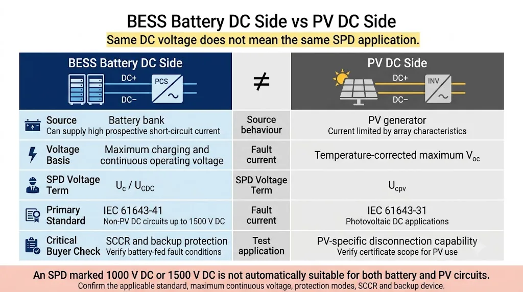
Source de batterie BESS
- Peut fournir un courant de court-circuit présumé élevé.
- La tension varie selon l'état de charge, l'état des cellules et les limites de charge.
- Peut utiliser des configurations flottantes, IT, à pôle mis à la terre ou à point milieu.
- Nécessite une déconnexion sûre dans des conditions de défaut alimentées par la batterie.
- Couverte par le champ d'application DC non-PV de la norme IEC 61643-41:2025.
Source du générateur PV
- Le courant est limité par les caractéristiques du champ PV.
- La tension maximale est principalement dérivée du Voc corrigé de la chaîne.
- La valeur nominale du produit est généralement indiquée sous la forme Ucpv.
- Les essais de défaillance et de déconnexion spécifiques au PV s'appliquent.
- Couvert par la norme IEC 61643-31 et sélectionné selon les recommandations spécifiques au PV.
| Élément de sélection | Côté batterie du BESS | Côté générateur PV | Implication pour l'acheteur |
|---|---|---|---|
| Comportement de la source | Source DC alimentée par batterie avec un courant de défaut présumé potentiellement élevé | Source PV limitée par les caractéristiques courant-tension du champ | Vérifiez la source réelle utilisée dans l'essai du produit et l'étude de défaut. |
| Base de tension | Tension maximale de charge et de fonctionnement continu | Tension Voc maximale de la chaîne corrigée en fonction de la température | Ne sélectionnez aucune des deux applications sur la seule base de la tension nominale. |
| Terme de tension couramment utilisé | Uc, UCDC ou tension continue maximale déclarée en régime permanent | Ucpv | Vérifiez la déclaration exacte dans la fiche technique du fournisseur et le rapport d'essai. |
| Norme d'application | IEC 61643-41 avec IEC 61643-01 | IEC 61643-31 | Un certificat réservé au photovoltaïque ne constitue pas automatiquement une preuve pour un circuit alimenté par batterie. |
| Vérification supplémentaire critique | SCCR, TOV, fusible de secours et déconnexion en toute sécurité | Comportement de fonctionnement et de déconnexion spécifique au photovoltaïque | Demandez l’ensemble de protection testé, et pas seulement In ou Imax. |
Quelle norme SPD s'applique à un circuit CC BESS ?
La norme applicable dépend du circuit à protéger, et non pas simplement du fait que le projet complet comporte des batteries ou des panneaux solaires.
| Circuit | Norme SPD applicable | Exemples de projets types | Vérification de l'acheteur |
|---|---|---|---|
| Circuit d'alimentation en courant continu alimenté par batterie | IEC 61643-41:2025 en liaison avec la norme IEC 61643-01:2024 | Sortie du rack de batteries, armoire de batteries, combineur CC, entrée CC du PCS | Demander les résultats des essais en courant continu (CC) du système BESS (hors photovoltaïque) ainsi que les conditions de défaut déclarées. |
| Circuit DC photovoltaïque | IEC 61643-31:2018 | Chaîne photovoltaïque, boîtier de raccordement et entrée CC de l'onduleur photovoltaïque | Vérifier le champ d'application des certificats spécifiques à l'UCPV et au PV. |
| Côté CA du PCS | IEC 61643-11:2025 en conjonction avec la norme IEC 61643-01 | Sortie CA du PCS, tableau de distribution et raccordement au réseau | Vérifier la tension alternative, le système de mise à la terre, le type et les modes de protection. |
| Communication et signalisation | IEC 61643-21 : 2025 | RS485, CAN, Ethernet, circuits d'alarme, de capteurs et de surveillance | Adaptez la tension du signal, le débit de données, la configuration des lignes et le type d'interface. |
Comment sélectionner un SPD CC BESS
L’ordre de sélection est important. Commencer par l’Imax ou le nombre de pôles du produit peut conduire à un SPD présentant une capacité de résistance aux surtensions impressionnante, mais incompatible avec le circuit de la batterie en question.
Déterminer le point exact de protection en courant continu
Précisez si le SPD sera installé au niveau de la sortie d'un râtelier de batteries, de la sortie d'une armoire de batteries, d'un combineur CC, d'un convertisseur CC/CC, du bus CC principal ou de l'entrée CC du PCS.
Vérifiez la tension maximale en continu
Respectez la tension de charge maximale autorisée de la batterie et les limites réelles de fonctionnement.
Vérifier les modes de mise à la terre et de protection
Déterminez si le circuit continu est flottant, de type IT, à mise à la terre positive, à mise à la terre négative, à mise à la terre au point milieu ou s'il s'agit d'une autre configuration.
Vérifier la tension de tenue des équipements et les parafoudres (SPD) Up
Indiquez la tension aux bornes de connexion, et pas seulement la tension « Up » indiquée dans la fiche technique.
Vérifier le SCCR et la protection par sauvegarde
Déterminer le courant de court-circuit prévisible au point d'installation.
Sélectionnez « Type 1 », « Type 1+2 » ou « Type 2 » dans la liste des risques
Tenez compte de l'évaluation des risques liés à la foudre, du LPS, des limites des LPZ et de l'exposition des câbles.
Vérifier l'installation, la surveillance et la maintenance
Vérifiez la longueur des câbles, le boîtier, l'environnement, l'affichage, le contact à distance et l'accès pour l'entretien.
Ne pas sélectionner le SPD en fonction de la tension nominale du BESS
Un système commercialisé sous l'appellation « BESS 1 000 V » peut fonctionner sur une large plage de tensions.
Contrôle de base de la tension maximale
Comparez ce résultat à la tension d'entrée CC maximale du PCS et aux limites de fonctionnement du système.
Exemple
Supposons qu'une chaîne de batteries comporte 14 modules montés en série. La tension nominale d'un module est de 64 V, mais la tension de charge maximale autorisée est de 72 V.
Tension de charge maximale : 14 × 72 V = 1 008 V CC
| Données relatives à la tension | Où se le procurer ? | Comment cela influe sur le choix du SPD |
|---|---|---|
| Tension nominale de la batterie | Caractéristiques techniques du système de batterie | Indique la classe de tension, mais ne constitue pas la valeur finale de Uc. |
| Tension de charge maximale d'une cellule ou d'un module | Données du fabricant de la batterie | Utilisé avec la quantité en série pour calculer la tension maximale de la chaîne. |
| Tension d'entrée CC maximale du PCS | Fiche technique et mode d'emploi du PCS | Vérifie l'interface du convertisseur et la limite de fonctionnement absolue. |
| Tension par rapport à la terre selon le mode de protection | Schéma unifilaire et étude de mise à la terre | Détermine la contrainte continue sur les chemins +/PE, −/PE et +/−. |
| TOV ou condition de fonctionnement anormale | Étude des défauts du réseau et de l'isolation | Vérifie si le SPD peut rester stable en cas de surtension non liée à une surintensité. |
Confirmer l'arrangement de mise à la terre du BESS DC avant de choisir le nombre de pôles
Le nombre et la disposition appropriés des composants de protection dépendent de la tension entre le pôle positif, le pôle négatif et la terre de protection, en conditions normales et en cas de défaut.
Système DC flottant ou informatique
Aucune des deux bornes n'est reliée de manière intentionnelle et solide à la terre. Vérifiez les deux chemins entre les bornes et la terre ainsi que les conditions de premier défaut à la terre.
Système à pôle mis à la terre
Un pôle est intentionnellement relié à la terre. Les chemins de protection requis diffèrent de ceux d'un système flottant.
Point médian ou topologie particulière
Une topologie interne de type « midpoint », « split bus », « DC/DC » ou « PCS » peut modifier la tension appliquée à chaque composant du SPD.
| Question fondamentale | Informations requises | Pourquoi cela modifie-t-il la SPD ? |
|---|---|---|
| Le bus de batterie est-il isolé de la terre ? | Flottante, alimentée par le réseau ou surveillée par un dispositif de surveillance d'isolement | Modifie la tension normale et la tension de premier défaut sur les circuits pôle-terre. |
| L'un des pôles est-il mis à la terre intentionnellement ? | Mise à la terre positive, négative ou absence de pôle solide | Modifie les modes de protection requis et leur tension continue. |
| Un point médian est-il relié à la terre ? | Raccordement au point médian et déséquilibre admissible | Modifie la contrainte entre le pôle et la terre ainsi que la disposition des composants. |
| Que se passe-t-il après le premier défaut à la terre ? | Alarme, poursuite du fonctionnement ou arrêt immédiat | Permet de déterminer la contrainte de tension temporaire sur le pôle en bon état. |
| Le PCS est-il isolé galvaniquement ? | Dispositif d'isolation pour convertisseur et transformateur | Permet de modifier le système CC effectif et le chemin de défaut. |
SCCR et protection de secours sont des vérifications obligatoires pour le BESS
Un parc de batteries peut générer un courant de défaut important. Vérifiez le parasurtenseur dans le cadre d’une branche entièrement protégée.
| Paramètres | Ce qu'elle décrit | Ce que cela ne prouve pas |
|---|---|---|
| En | Courant de décharge nominal pour la forme d'onde impulsionnelle spécifiée | Interruption en toute sécurité d'un défaut à fréquence du réseau alimenté par batterie. |
| Imax | Valeur maximale de courant de décharge de type 2 lors des essais | Convient à tous les niveaux d'exposition au système de stockage d'énergie par batterie (BESS) ou à tous les systèmes de mise à la terre. |
| Iimp | Capacité de résistance aux courants de foudre de type 1 | Coordination adéquate des valeurs Uc, Up, SCCR ou des fusibles de secours. |
| Haut de la page | Niveau de protection contre les surtensions lors de l'essai de surtension spécifié | Tension finale au niveau du PCS après l'inductance du câble de raccordement. |
| SCCR / Isccr | Performances en cas de court-circuit déclarées dans des conditions spécifiées | Compatibilité en cas de différence entre le courant de défaut du projet et celui du fusible de secours. |
Le côté CC du BESS doit-il utiliser le SPD Type 1+2 ou le SPD Type 2 ?
La réponse dépend du concept de protection contre la foudre et de la transition entre les zones LPZ.
Déterminer s'il s'agit d'un cas de type 1 ou de type 1+2 lorsque
- Un courant de décharge partielle peut s'introduire dans le circuit à courant continu.
- La ligne traverse une zone de protection exposée.
- Un LPS externe est présent et la séparation ne peut être maintenue.
- L'évaluation des risques du projet nécessite une capacité de support des courants de foudre.
Le type 2 peut être indiqué lorsque
- Le circuit se trouve dans une zone LPZ protégée.
- Seules des surtensions induites et de commutation sont attendues.
- Le câble est acheminé dans une zone convenablement protégée.
- Le cahier des charges du projet prend en charge le Type 2.
Où le SPD doit-il être installé entre le cabinet de batteries et le PCS ?
Protégez le bornier de l'équipement et la limite de la zone où la surtension pénètre.
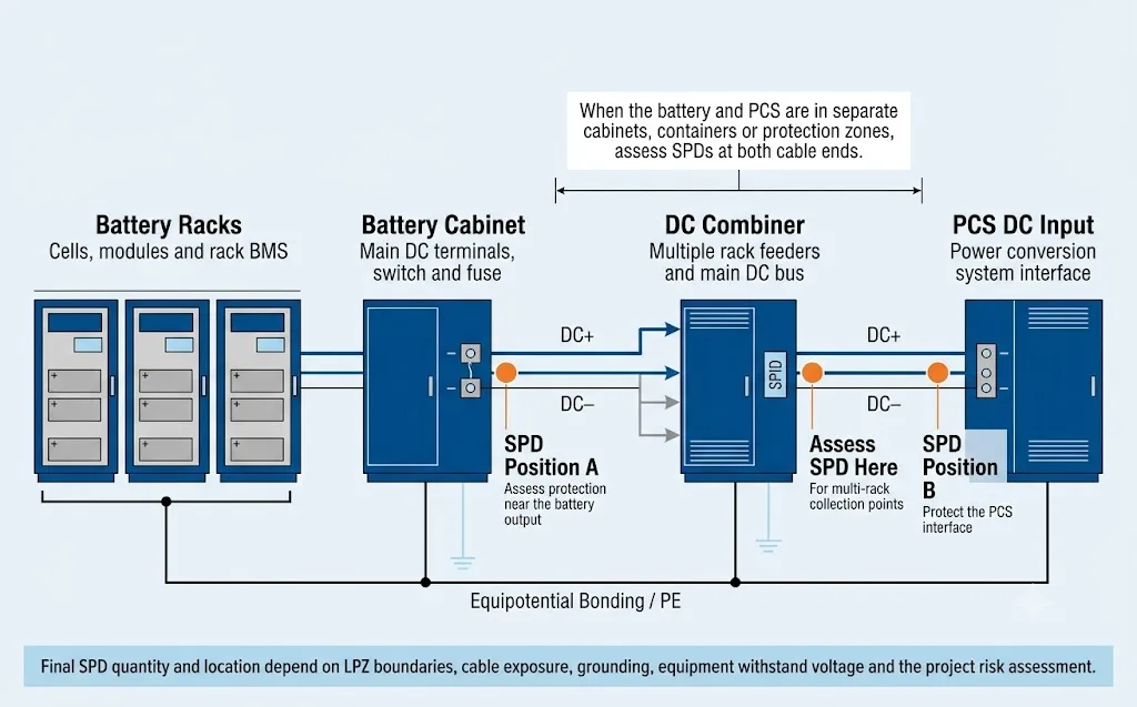
Schéma de sélection simplifié. Il ne s'agit pas d'un schéma de câblage et ce document ne remplace pas le schéma unifilaire du projet.
| Configuration du système | Emplacements possibles pour les SPD | Vérifications importantes |
|---|---|---|
| Batterie et PCS dans une seule armoire intégrée | À proximité du PCS protégé ou du point de distribution DC désigné | Disposition interne, longueur des câbles et résistance du boîtier. |
| Batterie et PCS dans des armoires adjacentes | Sortie de la batterie, entrée du PCS ou les deux, après examen de la coordination | Tracé des câbles, mise à la terre commune et coordination Up/Uw des équipements. |
| Batterie et PCS dans des conteneurs distincts | Vérifiez systématiquement les deux extrémités du câble d'interconnexion CC. | LPS, tracé souterrain ou aérien, blindage et mise à la terre. |
| Plusieurs baies via un combineur CC | Alimentateur en rack, bus principal du combinateur et/ou entrée PCS | Contribution du courant parallèle et coordination des SPD. |
Chaque BESS a-t-il besoin de SPDs à chaque extrémité lorsque le câble dépasse 10 m ?
Aucune règle générale relative aux systèmes de stockage d'énergie par batterie (BESS) ne doit se limiter à la seule longueur de câble. La distance souvent citée n'a de sens que si elle est prise en compte conjointement avec la zone de protection, le tracé du câble, le dispositif de mise à la terre et le niveau de résistance de l'équipement distant.
Les directives d'application peuvent autoriser un seul SPD dans une configuration particulière où la batterie et le PCS partagent un système de mise à la terre relié et où le câble d'interconnexion reste à l'intérieur d'un cheminement correctement protégé. Cet exemple conditionnel ne doit pas être considéré comme une règle générale applicable à tous les conteneurs de systèmes de stockage d'énergie par batterie (BESS) et à tous les câbles extérieurs.[8]
| Question de décision | Pourquoi c'est important |
|---|---|
| Le câble traverse-t-il une limite de zone de protection contre les foudre (LPZ) ? | Permet de déterminer les points d'entrée des courants de surtension et les emplacements où un dispositif de protection contre les surtensions (SPD) doit être installé de manière coordonnée. |
| Le câble est-il en surface, enterré ou logé dans une gaine métallique ? | Modifie l'exposition au couplage électromagnétique lié à la foudre. |
| Ces deux structures partagent-elles un même système de mise à la terre relié ? | Des différences de potentiel peuvent provoquer un courant de pointe dans la connexion CC. |
| Que sont le PCS et la borne de batterie Uw ? | Détermine si la tension résiduelle à l'extrémité distante reste dans les limites acceptables. |
| Les deux SPD peuvent-ils être installés avec des câbles courts ? | Les câbles trop longs génèrent une tension inductive et peuvent rendre inopérant un Up qui serait par ailleurs adapté. |
Un SPD de puissance CC ne protège pas les lignes de communication BMS
La disponibilité du système BESS dépend de la communication entre les baies de batteries, le BMS, le PCS, l’EMS, les systèmes anti-incendie et les équipements de télésurveillance.
Liste de contrôle pour la commande de SPD CC BESS
« 1 500 V, 40 kA, 2P » ne suffit pas pour formuler une recommandation responsable concernant un système de stockage d'énergie par batterie (BESS).
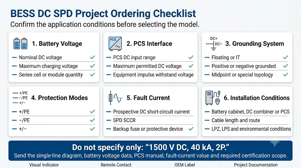
| Paramètres | Informations à fournir | Pourquoi le fournisseur en a besoin |
|---|---|---|
| Point d'application | Rack de batteries, armoire, combinateur, bus CC, convertisseur CC/CC ou entrée PCS | Définit l'équipement source et l'équipement protégé. |
| Tension continue nominale | Tension nominale normale du système de batterie | Indique la classe de tension générale. |
| Tension de charge maximale | Tension continue maximale autorisée de la batterie | Critère principal pour la sélection de Uc ou UCDC. |
| Configuration de la batterie | Type de cellule/module et nombre de cellules en série/parallèle | Permet de vérifier l'enveloppe de fonctionnement. |
| Plage d'entrée CC du PCS | Tension d'entrée CC minimale, nominale et maximale | Confirme la compatibilité de l'interface. |
| Système de mise à la terre CC | Flottant, IT, mise à la terre par le pôle positif, mise à la terre par le pôle négatif ou mise à la terre au point médian | Détermine les modes de protection et les tensions de test. |
| Courant de défaut prévisionnel | Courant de court-circuit en courant continu calculé au point du dispositif de protection contre la surtension (SPD) | Obligatoire pour la vérification du SCCR et des périphériques de sauvegarde. |
| Protection des branches existantes | Type de fusible ou de disjoncteur, tension, intensité et pouvoir de coupure | Vérifie la cohérence avec les instructions du SPD. |
| Équipement Uw | Tension de tenue aux impulsions des bornes de la batterie, du BMS, du combinateur et du PCS | Vérifie que le niveau de protection mis en place est suffisant. |
| Longueur et tracé du câble | Longueur, tracé en surface/souterrain, blindage et confinement | Facilite la prise de décisions en matière d'affectation et de coordination. |
| Conditions environnementales | Température, altitude, humidité, salinité, vibrations et niveau de pollution | Cela a une incidence sur l'isolation, la réduction de la puissance nominale et la conception du boîtier. |
| Exigences OEM | Logo, étiquette, référence, emballage et documentation | Permet une analyse précise des aspects commerciaux et de production. |
Transformer les données du projet BESS en une spécification finale de SPD
Les données issues de l'enquête devraient déboucher sur un résultat technique concret. Sans cette conversion, l'acheteur reçoit une liste de questions, mais ne peut toujours pas comparer les fournisseurs sur un pied d'égalité.
| Données d'entrée du projet | Décision technique | Champ « Spécifications finales du SPD » |
|---|---|---|
| Tension de charge maximale et tension par rapport à la terre | Choisissez une tension nominale continue qui reste stable dans tous les modes requis | Uc / UCDC par mode de protection |
| Topologie flottante, à pôle mis à la terre ou au point milieu | Définissez les circuits nécessitant une limitation des surtensions | +/PE, −/PE, +/− et disposition des modules |
| Tension de tenue aux impulsions des batteries, des PCS et des combineurs | Définir la tension résiduelle installée maximale admissible | Augmentation liée au mode de protection et aux exigences en matière de longueur de câble |
| LPS, LPZ et exposition des câbles | Déterminer la classe de pic de courant et la charge énergétique prévues | Type 1, Type 1+2 ou Type 2 ; Iimp, In et Imax |
| Courant de court-circuit théorique de la batterie | Vérifier la déconnexion en toute sécurité dans les conditions réelles de la source | SCCR / Isccr et fusible de secours homologué |
| Disposition de la batterie par rapport au système de contrôle de puissance (PCS) et cheminement des câbles | Déterminez si une seule extrémité du câble ou les deux nécessitent une protection coordonnée | Point d'installation A, point B ou configuration coordonnée en deux étapes |
| Exigences en matière d'entretien et de surveillance | Définir les fonctions de service et d'état à distance | Module enfichable, indicateur visuel et contact à distance |
| Liste des projets et des autorisations | Valider la portée acceptable des tests et de la documentation | Justificatifs, rapports et déclarations conformes aux normes CEI/EN/UL |
Fiche technique finale minimale
Utilisez les critères suivants pour comparer les devis. Un fournisseur ne doit pas remplacer un élément manquant par une brochure générale sur ses produits.
Trois cas typiques de sélection de SPD CC BESS
Ces exemples illustrent le processus de décision plutôt que de proposer un modèle universel. Les valeurs finales doivent être tirées des données réelles de la batterie, du PCS et de la documentation du projet.
Armoire intégrant la batterie et le système de contrôle de puissance (PCS)
- Condition du projet
- La batterie et le PCS partagent un même boîtier scellé, doté de conducteurs CC internes courts.
- Critique principale
- Tension maximale de la batterie, topologie de mise à la terre, puissance nominale (Uw) du système de conversion d'énergie (PCS), longueur des câbles internes et courant de défaut.
- Parcours décisionnel probable
- Prévoir un emplacement SPD coordonné à proximité de l'interface de distribution PCS/DC protégée, en fonction de la conception de l'armoire.
Boîtier de batterie séparé du PCS
- Condition du projet
- Un câble CC extérieur relie deux armoires ou conteneurs et peut franchir la limite d'une zone LPZ.
- Critique principale
- LPS, cheminement des câbles, mise à la terre commune, puissance apparente (Uw) des équipements déportés, exposition des conducteurs et emplacement des deux bornes.
- Parcours décisionnel probable
- Évaluez la protection coordonnée à la fois au niveau de la sortie de la batterie et de l'entrée du PCS, plutôt que de vous baser uniquement sur la longueur du câble.
Plusieurs racks de batteries reliés par un combineur de courant continu
- Condition du projet
- Plusieurs alimentateurs en rack parallèles sont raccordés à un combinateur CC commun avant le PCS.
- Critique principale
- Contribution parallèle au courant de défaut, protection des lignes d'alimentation, capacité SCCR du bus principal, emplacement des combinateurs et coordination des systèmes de compensation de puissance (PCS).
- Parcours décisionnel probable
- Considérez la protection des dérivations, des combinateurs et des PCS comme un système coordonné ; ne choisissez pas le SPD en vous basant uniquement sur la valeur Imax.
Quelles preuves un fournisseur de SPD CC BESS doit-il fournir ?
Une déclaration du fournisseur telle que « adapté aux systèmes de stockage d'énergie par batterie (BESS) de 1 500 V » n'est pas suffisante en soi. L'acheteur doit vérifier le champ d'application et les conditions qui sous-tendent cette affirmation.
- Norme d'essai applicablePortée du rapport ou du certificat précisant le fondement de l’application « non photovoltaïque » en courant continu ou « BESS ».
- Déclaré Uc / UCDCTension nominale continue pour chaque mode de protection requis, et pas seulement la tension totale du système.
- Mode de protection : HautNiveau de protection contre les surtensions pour la configuration réelle +/PE, −/PE et/ou +/−.
- Conditions SCCR / IsccrIntensité nominale de court-circuit déclarée et dispositif de protection de secours testé ou homologué.
- Instructions relatives au fusible de secoursCatégorie de fusible, tension nominale, intensité nominale, pouvoir de coupure et valeur maximale admissible.
- Schéma de raccordementCâblage correct du système de mise à la terre du projet et disposition des modules.
- Notations environnementalesTempérature, altitude, environnement, pollution, vibrations et autres contraintes pertinentes.
- Cohérence de la productionTraçabilité, contrôle des composants à leur réception, inspections de routine et processus de gestion des modifications.
- Informations relatives au suiviÉtat de l'indicateur, intensité admissible en contact à distance et instructions de remplacement ou d'entretien.
- Cohérence des documentsL'étiquette du produit, la fiche technique, le rapport d'essai, le devis et l'emballage doivent tous faire référence au même modèle.
Erreurs courantes dans la spécification du SPD CC BESS
Questions fréquemment posées sur la sélection de SPD CC BESS
Un parafoudre DC PV peut-il être utilisé du côté des batteries d'un BESS ?
Pas automatiquement. Le fournisseur doit fournir la preuve que le produit est adapté à la tension du circuit de la batterie, à la source d'alimentation, au courant de court-circuit et aux modes de protection.
Une spécification BESS doit-elle utiliser Uc ou Ucpv ?
Ucpv est la désignation spécifique aux installations photovoltaïques. Pour un circuit de batterie BESS non photovoltaïque, utilisez la tension continue maximale en service continu indiquée par le fabricant, généralement désignée par Uc ou UCDC.
Puis-je sélectionner un SPD de 1000 V pour un BESS nominal de 1000 V ?
Pas uniquement à partir de la tension nominale. Calculez la tension maximale de charge de la batterie et vérifiez la tension continue pour chaque mode de protection.
Un SPD doit-il être installé à la fois à la batterie et au PCS ?
Il convient d'évaluer les deux extrémités lorsque la batterie et le PCS se trouvent dans des armoires, des conteneurs, des bâtiments ou des zones de protection distincts.
Les lignes de communication BMS ont-elles besoin d'une protection contre les surtensions séparée ?
Oui, lorsque l'évaluation des risques met en évidence une exposition. Un parasurtenseur à courant continu ne protège pas les interfaces RS485, CAN, Ethernet, ni les capteurs ou les interfaces de commande.
Un Uc plus élevé peut-il toujours être utilisé pour une sécurité supplémentaire ?
Non. Une tension nominale continue plus élevée peut réduire les déclenchements intempestifs, mais elle peut également augmenter la tension Up. Le SPD sélectionné doit rester stable à la tension de fonctionnement maximale tout en continuant à protéger l’isolation du PCS et de la batterie.
SCCR est-il la même chose que Imax ?
Non. L'Imax est un paramètre lié au courant de décharge impulsionnel. Le SCCR ou Isccr concerne le comportement déclaré du produit en cas de court-circuit de la source d'alimentation et dépend généralement d'un dispositif de protection de secours homologué.
Quels documents doivent être joints à une demande d'information sur un SPD DC BESS ?
Joignez le schéma unifilaire, les données relatives à la tension maximale de la batterie, le manuel du PCS, les informations relatives à la mise à la terre, la valeur prévisionnelle du courant de défaut, le plan d'implantation de l'armoire, le tracé des câbles, les normes applicables et les exigences en matière de documentation de l'équipementier.
Demander un examen de l'application du SPD CC BESS
Veuillez nous transmettre les spécifications du projet afin que nous puissions examiner la tension, les modes de protection, le courant de défaut, la protection de secours et l'emplacement d'installation avant de vous recommander un modèle.
- Tension maximale de la batterie
- Plage d'entrée CC du PCS
- Topologie de mise à la terre en courant continu
- Courant de défaut prévisionnel
- Schéma unifilaire
- Disposition des armoires et des câbles
- Norme SPD requise
- Besoins en matière d'équipement d'origine (OEM) et de documentation
Références
- Commission électrotechnique internationale, IEC 61643-41:2025 — Dispositifs de protection contre les surtensions raccordés aux réseaux d'alimentation à courant continu basse tension .
- Commission électrotechnique internationale, IEC 61643-31:2018 — Exigences et méthodes d'essai relatives aux parafoudres destinés aux installations photovoltaïques .
- Commission électrotechnique internationale, IEC 61643-01:2024 — Exigences générales et méthodes d'essai pour les dispositifs de protection contre les surtensions (SPD) à basse tension .
- Commission électrotechnique internationale, IEC 62305-2:2024 — Protection contre la foudre, gestion des risques .
- Commission électrotechnique internationale, IEC 62305-4:2024 — Systèmes électriques et électroniques au sein des ouvrages .
- Commission électrotechnique internationale, IEC 61643-21:2025 — Dispositifs de protection contre les surtensions (SPD) raccordés aux réseaux de télécommunications et de signalisation .
- ABB Furse, Protection des systèmes de stockage d'énergie par batterie — Série ESP BESS de parafoudres pour lignes électriques en courant continu .
- Raycap, Protection contre les pics de tension et les surtensions dans les systèmes de stockage d'énergie par batterie .
- Mersen, Solutions de protection pour les systèmes de stockage d'énergie par batterie .
