
Tiang CCTV outdoor bukan hanya penopang kamera. Tiang ini dapat terhubung ke kabel PoE, daya AC atau DC, video BNC, kabel kontrol RS485, kabinet logam, dan kabinet jaringan jarak jauh.
Setiap jalur konduktif yang keluar dari tiang dapat membawa lonjakan menuju kamera atau kembali ke switch, NVR, atau ruang kontrol. Karena itu, rencana proteksi harus mengidentifikasi setiap sirkuit yang terpapar dan kedua ujung jalur kabel outdoor.
Panduan ini menjelaskan di mana SPD harus dievaluasi untuk kamera yang dipasang pada tiang, bagaimana pembumian tiang dan ikatan equipotensial memengaruhi instalasi, serta apa yang harus dikonfirmasi oleh pemasang atau pembeli proyek sebelum memesan.
Daftar Isi
Jawaban Singkat: Di Mana SPD Harus Dipasang?
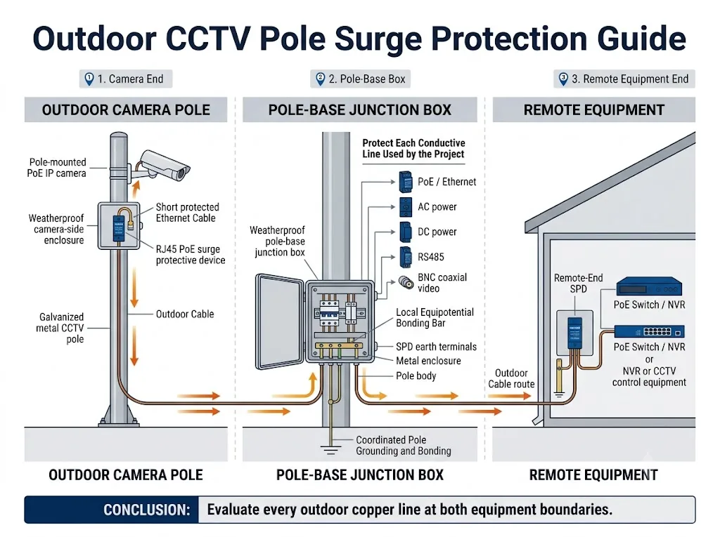
Evaluasi proteksi pada tiga batas: dekat kamera, di dalam kotak sambungan dasar tiang, dan sebelum kabel outdoor mencapai peralatan jarak jauh.
SPD di sisi kamera tidak otomatis melindungi switch jarak jauh. SPD di sisi switch tidak otomatis melindungi kamera. Lokasi yang diperlukan bergantung pada perutean kabel, paparan, zona proteksi petir, ikatan, dan penilaian risiko proyek.[1][3][7][13]
Lindungi batas kabel outdoor dan setiap sirkuit konduktif yang benar-benar digunakan oleh tiang. Jangan memilih proteksi hanya berdasarkan jumlah kamera.
Dalam Panduan Ini
Setiap lokasi proteksi melayani peralatan yang berbeda. Satu lokasi tidak boleh diasumsikan mencakup seluruh jalur kabel.
| Batas proteksi | Lokasi SPD tipikal | Peralatan yang dilindungi |
|---|---|---|
| Ujung kamera | Di dekat kamera atau di dalam penutup tahan cuaca yang sesuai | Kamera, unit PTZ, dan antarmuka kamera lokal |
| Kotak dasar tiang | Tempat kabel masuk atau keluar dari kotak sambungan | Saklar lokal, catu daya, terminal, dan peralatan tiang |
| Ujung jauh | Sebelum kabel luar ruangan mencapai switch, injektor, NVR, atau kabinet | Jaringan pusat, perekaman, dan peralatan kontrol |
Mengapa Tiang Kamera Outdoor Memerlukan Rencana Proteksi Terpisah?
Tiang dan kabelnya terpapar di luar ruangan
Tiang kamera umumnya dipasang di samping jalan, gerbang, tempat parkir, pagar perimeter, dan area industri terbuka. Peristiwa petir di sekitar dapat menginduksi tegangan transien pada konduktor tembaga yang panjang meskipun petir tidak menyambar kamera secara langsung.
IEC 62305 memisahkan penilaian risiko petir, proteksi petir fisik, dan langkah proteksi surja untuk sistem listrik dan elektronik. Langkah yang diperlukan tidak dapat ditentukan hanya dari tinggi tiang atau jenis kamera.[1][2][3]
Satu kamera dapat memiliki beberapa jalur masuk surja
Kamera yang dipasang pada tiang dapat menggunakan Ethernet PoE, daya AC, daya DC tegangan rendah, video koaksial BNC, kabel kontrol RS485, konduktor alarm, atau pelindung kabel logam.
Rangkaian ini memiliki tegangan kerja, persyaratan sinyal, dan susunan konduktor yang berbeda. Satu SPD umum tidak boleh diasumsikan mampu melindungi antarmuka yang tidak saling berkaitan.
Tiang dan peralatan jarak jauh dapat mencapai potensial yang berbeda
Selama surja, perbedaan tegangan sementara dapat muncul antara sistem pembumian di sisi tiang dan sistem bonding di sisi bangunan. Kabel tembaga penghubung kemudian dapat membawa arus menuju kamera atau peralatan jarak jauh.
Karena itu, pembumian, bonding equipotensial, penataan jalur kabel, dan penempatan SPD harus ditinjau bersama.
Makna rekayasa: Surja yang masuk melalui satu kabel tiang kamera dapat merusak kamera dan juga sakelar multiport atau NVR yang melayani beberapa kamera.
Alur Keputusan Praktis Penempatan SPD
Apakah kabel dari kamera ke boks pendek dan terlindungi oleh struktur tiang yang terikat?
Jika kabelnya pendek, seluruhnya dirutekan di dalam tiang logam atau conduit yang terikat, dan berakhir dekat SPD pada boks tiang, SPD terpisah di sisi kamera mungkin tidak selalu diperlukan.
Tindakan: pastikan seluruh desain, jalur kabel, dan instruksi pabrikan sebelum mengabaikan proteksi di sisi kamera.
Apakah masih ada kabel terbuka di antara kamera dan boks di dasar tiang?
Jika kabel kamera dirutekan secara eksternal, relatif panjang, atau melewati area terbuka, evaluasi SPD yang dekat dengan antarmuka kamera.
Tindakan: gunakan perangkat yang sesuai untuk penggunaan luar ruang atau pasang SPD di dalam enclosure yang dipilih dengan benar.
Apakah kabel tembaga luar ruang masuk ke gedung, kabinet, atau switch jarak jauh?
Jika ya, evaluasi proteksi sebelum kabel tersebut mencapai switch, injektor, NVR, atau kabinet kontrol.
Tindakan: perlakukan titik penerima jarak jauh sebagai batas proteksi yang terpisah.
Apakah beberapa rangkaian konduktif digunakan pada tiang yang sama?
PoE, AC, DC, BNC, dan RS485 harus dievaluasi secara terpisah. Lindungi hanya rangkaian yang ada, tetapi jangan biarkan jalur konduktif terbuka tanpa peninjauan.
Tindakan: buat daftar rangkaian sebelum memilih produk atau menyiapkan gambar junction box.
Ini adalah alur pemilihan, bukan aturan pemasangan universal.
Susunan akhir bergantung pada standar yang berlaku, zona proteksi petir, konstruksi kabel, bonding lokal, instruksi peralatan, dan penilaian risiko proyek.
Tiga Batas Proteksi
Ujung Kamera
Lindungi antarmuka lokal ketika kabel terbuka masih ada di antara kamera dan titik proteksi utama pada boks tiang.
Boks Dasar Tiang
Koordinasikan proteksi daya, jaringan, dan sinyal pada titik masuk kabel lokal utama dan titik bonding.
Ujung Jauh
Cegah kabel luar ruang masuk ke switch, NVR, atau kabinet gedung tanpa peninjauan proteksi terpisah.
Perlindungan Sisi Kamera
Pasang perlindungan di sisi kamera ketika masih ada kabel terbuka di antara kamera dan kotak dasar tiang, atau ketika SPD lokal utama tidak dapat diposisikan dekat dengan antarmuka kamera yang dilindungi.
Jika SPD tidak dirating untuk paparan luar ruangan langsung, tempatkan di dalam boks yang sesuai dengan entri kabel tersegel, ruang pengawatan yang memadai, dan sambungan bonding yang praktis.
Panduan pemasangan kamera dari Holowits menunjukkan SPD di sisi kamera di dalam boks kedap air ketika boks jaringan tidak dapat diposisikan dekat dengan kamera.[11]
Konfirmasikan detail di sisi kamera berikut
- Metode catu daya kamera dan tegangan operasi maksimum
- Kecepatan Ethernet dan kebutuhan PoE
- Rute kabel dari kamera ke boks dan tingkat paparan
- Kabel berpelindung atau tanpa pelindung
- Posisi pemasangan dan bonding yang tersedia
- Tingkat IP atau NEMA enclosure yang diperlukan
- Kondisi suhu, kelembapan, dan korosi
Perlindungan Kotak Sambungan Dasar Tiang
Kotak dasar tiang sering menjadi titik perlindungan lokal utama. Kotak ini dapat menyediakan ruang untuk SPD terpisah untuk daya, jaringan, dan sinyal bersama dengan terminal, perlindungan hulu, dan batang bonding lokal.
Panduan aplikasi CCTV dari OBO mengidentifikasi kotak sambungan tiang kamera sebagai kemungkinan lokasi SPD dan merekomendasikan pemasangan perlindungan dekat peralatan yang dilindungi dengan sambungan pendek ke bonding ekuipotensial lokal.[12]
Tempatkan setiap SPD dekat dengan batas masuk kabelnya
Pasang SPD dekat titik kabel yang tidak terlindungi masuk ke dalam boks. Hindari menjalankan konduktor terlindungi dan tidak terlindungi bersama-sama dalam jarak yang panjang karena energi lonjakan dapat terkopel kembali ke sisi yang terlindungi.
Jaga agar konduktor bonding tetap pendek dan langsung
Lonjakan cepat menghasilkan tegangan sepanjang induktansi konduktor. Konduktor bonding yang panjang, berloop, atau dirutekan secara tidak perlu dapat meningkatkan tegangan yang diterima peralatan yang dilindungi.
Rute konduktor akhir dan luas penampang harus mengikuti standar instalasi yang berlaku, desain proyek, dan petunjuk SPD. Jangan menyalin ukuran kabel dari instalasi kamera lain yang tidak terkait.
Periksa ruang yang dapat digunakan, bukan hanya dimensi enclosure
- Pastikan ruang rel DIN dan lebar modul.
- Sediakan ruang untuk tekukan kabel, terminal, dan penggantian.
- Pisahkan kabel masuk dan kabel terlindungi.
- Periksa ukuran cable gland, drainase, dan pengendalian kondensasi.
- Pastikan enclosure rakitan lengkap memenuhi peringkat lingkungan yang disyaratkan.
Makna pembeli: Minta gambar kotak sambungan internal sebelum persetujuan akhir produk. Arah masuk kabel dan posisi bar bonding dapat memengaruhi format SPD mana yang praktis.
Sakelar Jarak Jauh, NVR, atau Perlindungan Titik Masuk Gedung
Kabel luar ruang dapat membawa energi lonjakan menuju peralatan pusat. Karena itu, SPD yang sesuai dapat dipasang sebelum kabel mencapai sakelar PoE, injektor, sakelar Ethernet, NVR, DVR, konverter media, atau lemari kontrol.
Arsitektur CCTV DEHN menggambarkan proteksi di kedua ujung sambungan kamera IP luar ruang. Kebutuhan yang tepat tetap bergantung pada paparan kabel, zona perlindungan petir, dan desain proyek.[13]
Apakah setiap tiang memerlukan SPD di ketiga lokasi tersebut?
Tidak. Ketiga titik tersebut merupakan batas perlindungan untuk dievaluasi. Jumlah akhir SPD bergantung pada jalur kabel, jarak, pelindung, pengikatan, perlindungan petir eksternal, dan lokasi terminasi kabel yang terpapar.
Apa yang Berubah Saat Tiang Kamera Menggunakan PoE?
Koneksi PoE membawa data dan daya melalui kabel yang sama. Oleh karena itu, SPD harus mempertahankan kinerja Ethernet yang diperlukan sekaligus mendukung pengaturan PoE kamera.
IEC 61643-21:2025 mencakup SPD yang dihubungkan ke jaringan telekomunikasi dan persinyalan, termasuk jaringan yang menyediakan daya pada jalur yang sama, seperti PoE.[5]
Untuk instalasi tiang, konfirmasikan empat hal berikut
- Jarak kamera ke kotak: tentukan apakah SPD utama dapat diletakkan cukup dekat dengan antarmuka kamera.
- Paparan luar ruangan: konfirmasikan apakah SPD tersebut atau selongsongnya cocok untuk lingkungan tersebut.
- Entri kabel jarak jauh: evaluasi perlindungan sebelum kabel luar ruangan mencapai switch atau NVR.
- Kinerja PoE aktual: konfirmasikan kecepatan data, jenis PoE, pasangan kabel yang dilindungi, arus, dan pelindung (shielding).
IEEE 802.3bt memperluas pengiriman PoE terstandarisasi melalui operasi empat pasangan. SPD yang dirancang berdasarkan pengaturan daya lebih rendah atau lama tidak boleh dianggap cocok untuk setiap kamera berdaya lebih tinggi.[9]
Batas kemampuan model: Kecepatan Ethernet, daya PoE, arus beban, dan peringkat lingkungan yang tersedia bervariasi tergantung model produk. Konfirmasikan lembar data LEEYEE saat ini dan dokumentasi khusus model sebelum menentukan spesifikasi perangkat.
Untuk pemilihan parameter PoE secara rinci, lihat Panduan Penempatan dan Pemilihan Pelindung Lonjakan Listrik PoE. Untuk pemeriksaan antarmuka RJ45 secara rinci, lihat Panduan Pemilihan Pelindung Lonjakan RJ45.
Jalur Tiang CCTV yang Berbeda Memerlukan SPD yang Berbeda
Daya AC, DC tegangan rendah, Ethernet PoE, video BNC, dan kontrol RS485 tidak memiliki kondisi kerja yang sama. Pilih masing-masing perangkat pelindung untuk sirkuit yang terhubung dengannya.
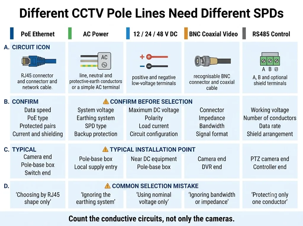
Gunakan kolom “Konfirmasikan sebelum memilih” sebagai permintaan informasi minimum untuk penawaran harga proyek.
| Jenis jalur | Konfirmasi sebelum pemilihan | Lokasi tipikal | Kesalahan umum |
|---|---|---|---|
| Ethernet PoE | Kecepatan data, jenis PoE, pasangan kabel yang dilindungi, arus, dan pelindung | Ujung kamera, kotak tiang, dan ujung switch jarak jauh | Memilih hanya berdasarkan bentuk RJ45 |
| Daya AC | Tegangan sistem, pengaturan pentanahan, tipe SPD, perlindungan cadangan, dan kondisi gangguan | Entri suplai kotak tiang dan panel hulu yang terkoordinasi | Mengabaikan sistem suplai dan pentanahan |
| 12/24/48 V DC | Tegangan operasi maksimum, polaritas, arus, sumber, dan konfigurasi sirkuit | Di dekat peralatan DC dan batas kabel kotak tiang | Memilih hanya dari tegangan nominal |
| Video koaksial BNC | Konektor, impedansi, lebar pita (bandwidth), dan format video | Ujung kamera dan ujung DVR atau penerima | Mengabaikan impedansi atau lebar pita (bandwidth) |
| Kontrol RS485 | Tegangan kerja, konduktor, laju data, dan pengaturan pelindung (shield) | Ujung kamera PTZ dan ujung pengontrol | Membiarkan jalur konduktor tidak diperiksa |
Kesimpulan pengadaan: hitung sirkuit konduktifnya, bukan hanya kameranya.
Daya AC
Kotak tiang yang dialiri daya AC memerlukan SPD yang dipilih untuk sistem daya dan posisi pemasangan yang sebenarnya. IEC 61643-11:2025 mencakup SPD yang terhubung ke sistem daya AC tegangan rendah.[4]
Konfirmasikan tegangan operasi kontinu maksimum, pengaturan pentanahan, tipe SPD, perlindungan hulu, kondisi hubung singkat prospektif, dan mode koneksi. Persyaratan ini harus berasal dari desain kelistrikan proyek.
Daya DC Tegangan Rendah
Suplai kamera 12 V, 24 V, atau 48 V memerlukan perangkat pelindung yang kompatibel dengan tegangan DC maksimum yang sebenarnya, polaritas, arus beban, karakteristik sumber, dan pengaturan konduktor.
IEC 61643-41:2025 mencakup SPD yang terhubung ke sistem daya DC tegangan rendah dan mencatat bahwa kondisi sumber dan gangguan memerlukan pertimbangan cermat.[6]
Jangan menyetujui SPD DC hanya karena labelnya mencantumkan tegangan nominal yang sama dengan kamera.
Video Koaksial BNC
Konfirmasikan konektor, impedansi karakteristik, lebar pita sinyal, dan teknologi video. Perangkat BNC yang kompatibel secara mekanis tetap bisa tidak sesuai jika kinerja transmisinya tidak cocok dengan sistem.
Kontrol RS485
Konfirmasikan tegangan kerja sirkuit, jumlah konduktor, laju data, dan perlakuan pelindung (shield). SPD daya AC tidak boleh diganti dengan SPD jalur data.
Pembumian dan Ikatan Equipotensial
Pentanahan dan pemasangan SPD harus dirancang sebagai satu sistem yang terkoordinasi. Keduanya saling terkait, namun tidak menjalankan fungsi yang sama.
Pembumian tiang
Tiang, elektrode lokal, atau struktur di dekatnya mungkin menjadi bagian dari pengaturan pentanahan proyek. Desain yang tepat bergantung pada kondisi tanah, persyaratan keselamatan listrik, risiko petir, peraturan lokal, dan spesifikasi proyek.
Jangan gunakan satu nilai resistansi pentanahan universal untuk setiap tiang kamera.
Pentanahan pelindung
Penutup logam, catu daya, sakelar, dan bagian konduktif terbuka mungkin memerlukan koneksi pentanahan pelindung untuk keselamatan listrik. Ikuti aturan pengabelan dan instruksi peralatan yang berlaku.
Pengikatan equipotential
Ikatan ekipotensial menghubungkan bagian-bagian konduktif agar perbedaan tegangan yang merusak cenderung tidak muncul di antara peralatan yang saling terhubung selama terjadi lonjakan arus.
Jika diperlukan oleh desain, tiang logam, penutup, terminal arde SPD, PE peralatan, dan pelindung kabel yang relevan harus terhubung melalui pengaturan ikatan lokal yang terkoordinasi. Holowits mengilustrasikan batang tembaga pentanahan umum di dalam kotak jaringan luar ruangan.[11]
Batang arde terpisah tidak secara otomatis menjadi solusi lengkap.
Jika elektrode lokal tidak terkoordinasi dengan sistem jarak jauh yang terhubung, lonjakan arus dapat menciptakan perbedaan potensial yang tinggi di seluruh kabel tembaga antara kedua lokasi tersebut. Pengaturan akhir harus ditinjau oleh personel proyek yang berkualifikasi.
Dapatkah SPD Melindungi Kamera dari Sambaran Petir Langsung?
SPD membatasi tegangan transien dan mengalihkan lonjakan arus pada sirkuit yang terhubung. Ini bukan sistem terminasi udara dan tidak menggantikan perlindungan petir eksternal.
IEC 62305-3 mencakup perlindungan petir fisik, sementara IEC 62305-4 mencakup tindakan perlindungan lonjakan arus untuk sistem kelistrikan dan elektronik. Ini adalah lapisan perlindungan yang terkoordinasi, tetapi salah satunya tidak boleh dianggap sebagai pengganti yang lain.[2][3]
Apakah suatu tiang memerlukan sistem terminasi udara, konduktor turun, jarak pemisahan, atau tindakan sambaran langsung lainnya harus ditentukan dari penilaian risiko lokasi dan aturan proyek yang berlaku.
Kesalahan Umum dalam Pemasangan SPD pada Tiang CCTV
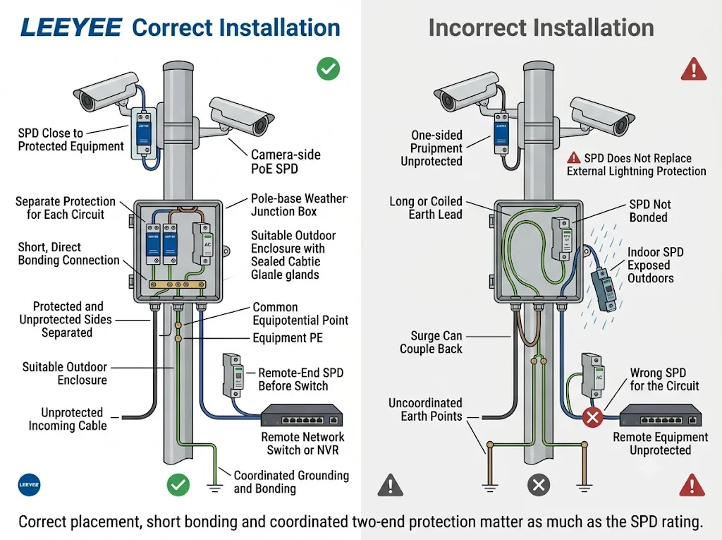
- Melindungi kamera saja. Kabel luar ruangan masih dapat membawa lonjakan arus ke sakelar jarak jauh atau NVR.
- Melindungi sakelar saja. SPD ujung jarak jauh tidak secara otomatis melindungi antarmuka kamera yang terbuka.
- Memasang SPD jauh dari peralatan. Panjang konduktor tambahan dapat meningkatkan tegangan residu dan memungkinkan kopling baru.
- Menggunakan kabel ikatan yang panjang atau melingkar. Koneksi harus mengikuti rute terpendek yang praktis sesuai desain.
- Mengasumsikan setiap SPD RJ45 mendukung setiap kamera PoE. Kecepatan, tipe PoE, pasangan kabel, arus, dan pelindung (shielding) harus diperiksa.
- Membiarkan SPD dalam ruangan terpapar di luar ruangan. Pemasangan lengkap memerlukan perlindungan lingkungan yang sesuai.
- Menjalankan kabel yang terlindungi dan tidak terlindungi secara bersamaan. Jalur paralel yang panjang dapat menyebabkan energi surja masuk kembali ke sisi yang dilindungi.
- Menggunakan satu SPD untuk sirkuit yang tidak kompatibel. AC, DC, PoE, BNC, dan RS485 memerlukan perlindungan yang sesuai dengan sirkuitnya.
- Membuat titik pentanahan (earth point) yang tidak saling terhubung. Kondisi bonding lokal dan jarak jauh harus dikoordinasikan melalui desain proyek.
- Memperlakukan SPD sebagai perlindungan terhadap sambaran langsung. Perlindungan petir eksternal tetap menjadi keputusan teknis yang terpisah.
Sebelum Memesan untuk Proyek Tiang CCTV dalam Jumlah Besar
Pemasok tidak dapat memberikan rekomendasi model yang andal hanya berdasarkan "kamera PoE luar ruangan". Siapkan informasi sistem yang sebenarnya sebelum menyetujui sampel atau melakukan pemesanan OEM.
Informasi kamera dan jaringan
- Model kamera atau lembar data teknis
- Jumlah kamera per tiang
- Kecepatan Ethernet
- Tipe PoE dan kebutuhan daya
- Kabel berpelindung atau tanpa pelindung
- Jalur kabel dari kamera ke kotak
- Jalur kabel dari tiang ke switch
- Model switch atau injector
Informasi daya dan sinyal
- Suplai AC atau DC
- Tegangan nominal dan maksimum
- Pengaturan pembumian
- Perlindungan sirkuit hulu (upstream)
- Konektor BNC dan format video
- Konduktor RS485 dan tegangan kerja
- Saluran alarm atau sinyal tambahan
- Metode terminasi pelindung kabel (cable shield)
Informasi mekanis dan proyek
- Material tiang dan lingkungan pemasangan
- Dimensi internal kotak sambungan
- Ruang rel DIN yang tersedia
- Posisi entri kabel dan batang bonding
- Tingkat penutup (enclosure) IP atau NEMA yang diperlukan
- Kondisi suhu dan korosi
- Standar atau spesifikasi proyek yang berlaku
- Sertifikat atau dokumen pengujian yang diperlukan
- Kuantitas proyek
- Label OEM atau persyaratan pengemasan
Persetujuan Teknis Sebelum Pemasangan Massal
Jangan menyetujui SPD tiang CCTV hanya berdasarkan foto produk, bentuk konektor, atau nilai arus surja pada judul.
Tinjauan teknis harus memverifikasi:
- Kompatibilitas sirkuit dan konektor
- Tegangan operasi maksimum yang kontinu.
- Performa data dan daya PoE
- Mode perlindungan dan konduktor yang dilindungi
- Kategori uji surja yang dinyatakan dan nilainya
- Tingkat perlindungan tegangan
- Kemampuan arus beban
- Metode grounding atau bonding
- Orientasi sisi lini dan sisi peralatan
- Dimensi pemasangan
- Penutup lingkungan
- Cakupan model sertifikat dan laporan
Untuk proyek ulangan, pasang dan uji sampel dengan kamera, switch, kabel, dan penutup yang sebenarnya sebelum menyetujui kuantitas penuh. Kriteria penerimaan lapangan harus disepakati oleh kontraktor, konsultan, dan pemilik proyek.
Konfirmasi Konfigurasi SPD Tiang CCTV
Bagikan lembar data kamera, kebutuhan PoE, suplai daya, jalur kabel, dimensi kotak tiang, dan kondisi grounding. Detail ini memungkinkan antarmuka AC, DC, PoE, BNC, dan RS485 ditinjau secara terpisah.
Minta Tinjauan Konfigurasi SPD Tiang CCTVLEEYEE adalah pemasok khusus perlindungan lonjakan arus dan perlindungan tegangan rendah. CNSPD adalah platform LEEYEE yang berfokus pada perlindungan lonjakan arus untuk pembeli teknis global.
Pertanyaan yang Sering Diajukan
Di mana pelindung surja harus dipasang pada tiang CCTV luar ruangan?
Evaluasi tiga batas: di dekat kamera, di dalam kotak dasar tiang, dan sebelum kabel luar ruangan mencapai peralatan jarak jauh. Lokasi yang diperlukan bergantung pada paparan kabel, jarak, bonding, dan desain proyek.
Apakah SPD dasar tiang sudah cukup untuk kamera?
Itu mungkin cukup jika kabel yang dilindungi di antara kotak tiang dan kamera pendek serta dirutekan dengan benar di dalam struktur yang terkoordinasi. Jika kabel yang terbuka masih ada, evaluasi perlindungan yang lebih dekat ke kamera.
Apakah setiap tiang kamera luar ruangan memerlukan SPD di kedua ujung kabel?
Tidak ada aturan universal yang berlaku untuk setiap proyek. Jalur kabel, zona proteksi petir, pengikatan (bonding), paparan, dan peralatan di setiap ujung harus ditinjau.
Apakah pembumian (grounding) tiang logam melindungi kamera?
Pembumian tiang hanyalah satu bagian dari sistem. Antarmuka kabel, koneksi SPD, penutup (enclosure), sakelar, dan peralatan jarak jauh tetap memerlukan proteksi dan pengikatan yang terkoordinasi.
Bisakah satu SPD melindungi PoE, daya AC, dan RS485?
Hanya jika perangkat dirancang dan diverifikasi secara khusus untuk setiap antarmuka yang disertakan. Pada sebagian besar proyek, jenis sirkuit yang tidak terkait dilindungi secara terpisah.
Bisakah SPD PoE dipasang di luar ruangan tanpa penutup (enclosure)?
Hanya jika perangkat lengkap, konektor, dan entri kabel memenuhi peringkat untuk lingkungan yang sebenarnya. Jika tidak, gunakan penutup yang sesuai dan ikuti petunjuk pemasangan.
Bisakah SPD melindungi kamera yang dipasang di tiang dari sambaran petir langsung?
SPD membatasi tegangan transien pada sirkuit yang terhubung. SPD tidak menggantikan sistem proteksi petir eksternal dan tidak dapat menjamin kelangsungan hidup dari setiap sambaran langsung.
Referensi
- Komisi Elektroteknik Internasional, IEC 62305-2:2024, Proteksi Terhadap Petir — Bagian 2: Manajemen Risiko.
- Komisi Elektroteknik Internasional, IEC 62305-3:2024, Proteksi Terhadap Petir — Bagian 3: Kerusakan Fisik pada Struktur dan Bahaya Kehidupan.
- Komisi Elektroteknik Internasional, IEC 62305-4:2024, Proteksi Terhadap Petir — Bagian 4: Sistem Elektrikal dan Elektronik di Dalam Struktur.
- Komisi Elektroteknik Internasional, IEC 61643-11:2025, Perangkat Proteksi Lonjakan Arus Tegangan Rendah — Bagian 11: SPD yang Terhubung ke Sistem Daya Tegangan Rendah AC — Persyaratan dan Metode Uji.
- Komisi Elektroteknik Internasional, IEC 61643-21:2025, Perangkat Proteksi Lonjakan Arus Tegangan Rendah — Bagian 21: SPD yang Terhubung ke Jaringan Telekomunikasi dan Persinyalan — Persyaratan dan Metode Uji.
- Komisi Elektroteknik Internasional, IEC 61643-41:2025, Perangkat Pelindung Lonjakan Tegangan Rendah — Bagian 41: SPD yang Dihubungkan ke Sistem Daya Tegangan Rendah DC — Persyaratan dan Metode Uji.
- Komisi Elektroteknik Internasional, IEC 61643-22:2015, Prinsip Pemilihan dan Penerapan untuk SPD yang Terhubung ke Jaringan Telekomunikasi dan Persinyalan.
- Komisi Elektroteknik Internasional, IEC 61643-12:2020, Prinsip Pemilihan dan Penerapan untuk SPD yang Terhubung ke Sirkuit Daya AC.
- IEEE Standards Association, IEEE 802.3bt-2018, Lapisan Fisik dan Parameter Manajemen untuk Power over Ethernet melalui Empat Pasangan.
- Komisi Elektroteknik Internasional, IEC 61643-01:2024, Perangkat Proteksi Lonjakan Arus Tegangan Rendah — Persyaratan Umum dan Metode Uji.
- Holowits, Panduan Rekayasa Proteksi Petir dan Pembumian Kamera.
- OBO Bettermann, Proteksi Lonjakan Arus untuk Sistem Televisi Sirkuit Tertutup (CCTV).
- DEHN, Proteksi Lonjakan Arus untuk Sistem CCTV.
