
Daftar Isi
Wiring TN-S SPD Sekilas
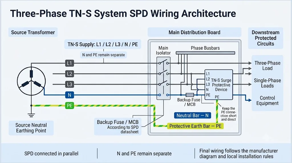
Dalam sistem TN-S tiga fase, perangkat perlindungan lonjakan dihubungkan secara paralel dengan L1, L2, L3, N dan PE sesuai dengan desain internal yang disetujui dari SPD yang dipilih. Netral dan bumi pelindung tetap terpisah selama operasi normal.
Jawaban Cepat: Bagaimana SPD Harus Dihubungkan dalam Sistem TN-S?
Di mana netral tersedia, gunakan susunan 4+0 / CT1 atau 3+1 / CT2 yang disetujui pabrikan. Hubungkan SPD dekat dengan busbar masuk, gunakan perlindungan cabang yang ditentukan, dan jaga sambungan SPD-ke-PE tetap sesingkat dan se langsung mungkin. Jangan pilih perangkat hanya berdasarkan jumlah tiang.
Pemilihan Cepat berdasarkan Kondisi Panel TN-S
| Kondisi Panel TN-S | Arah Pemilihan Umum | Apa yang Harus Dikonfirmasi Pembeli |
|---|---|---|
| L1 / L2 / L3 tanpa N Rangkaian tiga fase, tiga kawat | SPD 3P yang spesifik untuk proyek dapat digunakan. | Konfirmasi bahwa netral benar-benar tidak ada dan periksa diagram pengkabelan produk yang tepat. |
| L1 / L2 / L3 / N / PE Proyek menentukan CT1 | 4P / 4+0 / CT1 dapat dipilih. | Konfirmasi mode perlindungan L-PE dan N-PE, Uc, Up, perilaku TOV dan posisi RCD yang diizinkan. |
| L1 / L2 / L3 / N / PE Proyek menentukan CT2 | 3P+N / 3+1 / CT2 dapat dipilih. | Konfirmasi perlindungan L-N, komponen N-PE, Itotal, Aplikasi TN-S yang disetujui oleh produsen. |
| Pertanyaan hanya menyebutkan “SPD empat kutub” Sirkuit internal tidak disediakan | Jangan menyetujui model tersebut untuk saat ini. | Minta diagram satu garis, sirkuit SPD internal, dan mode perlindungan yang dibutuhkan. |
Deskripsi pasar “4P” dan “3P+N” tidak selalu memberikan cukup informasi untuk mengkonfirmasi sirkuit perlindungan internal.
Apa Itu Sistem Penetrasi TN-S?
Dalam sistem TN-S, netral sumber dihubungkan ke tanah, sementara konduktor netral dan konduktor tanah pelindung tetap terpisah dari sumber ke beban.
Pasokan TN-S tiga fase yang khas menggunakan lima konduktor: L1, L2, L3, N dan PE. Konduktor netral membawa arus kembali normal dari beban fase-ke-netral. Konduktor PE memberikan pengikatan pelindung dan jalur arus gangguan dan seharusnya tidak membawa arus beban normal.
Ini berbeda dari TN-C, di mana fungsi netral dan perlindungan digabungkan dalam konduktor PEN, dan TN-C-S, di mana konduktor PEN dipisahkan menjadi N dan PE pada titik tertentu.
Jangan mengidentifikasi TN-S hanya dari warna konduktor
Warna dapat bervariasi berdasarkan negara, usia instalasi, dan praktik lokal. Konfirmasikan sistem dari diagram satu garis proyek, dokumentasi pasokan, dan pengaturan N/PE yang sebenarnya.
L1, L2, L3, N dan PE dalam Diagram Wiring TN-S
| Konduktor | Fungsi Normal | Makna Pemilihan SPD | Kesalahan Umum |
|---|---|---|---|
| L1 / L2 / L3 Konduktor fase | Membawa tegangan pasokan tiga fase dan arus beban. | Setiap fase memerlukan mode perlindungan yang ditentukan oleh proyek dan sirkuit SPD. | Memilih SPD 3P hanya karena pasokan disebut sebagai “tiga fase.” |
| N Konduktor netral | Mengangkut arus kembali dari beban fase-ke-netral. | Konfirmasi apakah perangkat menyediakan perlindungan L-N, perlindungan N-PE atau kombinasi keduanya. | Dengan asumsi semua SPD modul empat melindungi netral dengan cara yang sama. |
| PE Tanah pelindung | Menyediakan pengikatan pelindung dan jalur pelepasan lonjakan. | Konduktor SPD-ke-PE harus pendek, langsung, dan berukuran sesuai dengan instruksi produk. | Memasang SPD jauh dari batang PE dan menggunakan kabel panjang melingkar. |
Cara Menghubungkan SPD di Panel TN-S Tiga Fase
SPD terhubung paralel dengan pasokan yang masuk. Arus beban normal tidak melewati SPD.
Konfirmasi pengaturan pasokan
Verifikasi L1, L2, L3, N dan PE dari diagram satu garis dan konfirmasikan bahwa sistem adalah TN-S di titik pemasangan SPD.
Sambungkan SPD secara paralel
Ambil sambungan fase dan netral yang diperlukan dari konduktor atau busbar yang masuk sesuai dengan diagram terminal SPD.
Pasang perlindungan cabang yang ditentukan
Gunakan fuse, MCB, atau perlindungan cadangan lain yang dinyatakan dalam lembar data SPD setelah memeriksa arus hubung singkat yang tersedia.
Sambungkan langsung ke batang PE
Jaga jalur tanah tetap pendek, langsung, dan bebas dari loop atau tikungan yang tidak perlu yang meningkatkan tegangan induktif.
Jaga N dan PE terpisah
Jangan menambahkan jembatan tembaga permanen antara batang netral dan batang PE di papan distribusi TN-S hulu.
Selesaikan verifikasi panel
Periksa torsi terminal, panjang kabel, perlindungan cadangan, kontak jarak jauh, modul pengganti, dan gambar akhir yang disetujui.
Dimensi pemasangan bersifat spesifik produk.
Jangan menyalin posisi terminal, ukuran konduktor, atau penilaian perangkat cadangan dari diagram internet generik. Gunakan petunjuk pemasangan yang tepat untuk model SPD yang dipesan.
3P vs 4P vs 3P+N SPD untuk Sistem TN-S
Jumlah kutub menggambarkan pengaturan fisik. Ini tidak sepenuhnya mendefinisikan jalur perlindungan lonjakan internal.
| Deskripsi Pasar | Logika Sirkuit Umum | Kemungkinan Penggunaan TN-S | Konfirmasi Pembeli |
|---|---|---|---|
| SPD 3P Perangkat tiga kutub | Melindungi konduktor fase tiga tanpa jalur netral yang khusus. | Sirkuit tiga fase tiga kawat atau desain spesifik proyek yang telah disetujui. | Pastikan bahwa netral tidak ada di lokasi SPD. |
| SPD 4P Perangkat empat kutub | Sering menggunakan 4+0 / CT1, dengan L1, L2, L3, dan N yang dilindungi terhadap PE. | Mungkin cocok jika produsen menyetujui perangkat tersebut untuk TN-S. | Konfirmasikan simbol sirkuit, mode perlindungan, Uc, Up, perilaku TOV, dan pengaturan RCD. |
| 3P+N SPD Tiga fase ditambah netral | Sering menggunakan 3+1 / CT2, dengan perlindungan L-N ditambah jalur N-PE terpisah. | Umumnya tersedia untuk sistem TN-S. | Konfirmasikan komponen N-PE, Itotal, Up, dan model bersertifikat yang tepat. |
Halaman ini membahas tentang pengabelan TN-S, bukan sekadar perbandingan produk
Untuk perbandingan struktur produk yang lebih mendalam, lihat Panduan SPD 3P+N vs SPD 4P. Halaman TN-S ini berfokus pada bagaimana jenis sistem, pengaturan konduktor, dan kondisi pemasangan memengaruhi keputusan akhir pengabelan.
Perlindungan 4+0 vs 3+1 dalam Sistem TN-S
Kedua pengaturan perlindungan mungkin tersedia untuk sistem TN-S, namun keduanya menciptakan jalur lonjakan arus yang berbeda. [3]
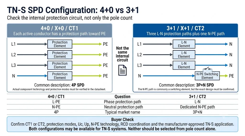
| Perbandingan | 4+0 / X+0 / CT1 | 3+1 / X+1 / CT2 |
|---|---|---|
| Jalur perlindungan fase | Umumnya L1-PE, L2-PE, dan L3-PE | Umumnya L1-N, L2-N, dan L3-N |
| Jalur proteksi netral-ke-ground | Elemen proteksi N-PE | Jalur pensaklaran N-PE khusus |
| Deskripsi pasar umum | SPD 4P | 3P+N SPD |
| Pemeriksaan pembelian utama | Mode L-PE dan N-PE, perilaku TOV, Uc, Up, dan posisi pemasangan | Mode L-N, teknologi N-PE, Itotal, Up gabungan dan posisi pemasangan |
| Bisakah digunakan pada sistem TN-S? | Ya, jika disetujui oleh produsen dan spesifikasi proyek | Ya, jika disetujui oleh produsen dan spesifikasi proyek |
Tidak ada pemenang universal
Pengaturan yang tepat bergantung pada spesifikasi proyek, jenis SPD, mode perlindungan, tingkat perlindungan tegangan, kinerja TOV, koordinasi RCD, beban arus petir, dan aplikasi yang disetujui oleh produsen.
Apakah Sistem TN-S Memerlukan Perlindungan Lonjakan N-PE?
Jika terdapat netral, perakitan SPD yang dipilih biasanya memerlukan pengaturan perlindungan lonjakan arus terkait netral yang terdefinisi dengan jelas. Bergantung pada sirkuitnya, ini mungkin merupakan bagian dari desain 4+0 / CT1 atau 3+1 / CT2.
Pada perangkat CT1, N mungkin memiliki jalur perlindungan menuju PE. Pada perangkat CT2, perlindungan fase biasanya beroperasi dari L ke N, dengan jalur pensaklaran N-PE yang terpisah. [4]
Perlindungan lonjakan arus N-PE bukanlah koneksi N-PE permanen.
Elemen perlindungan SPD dirancang untuk merespons dalam kondisi tegangan lebih yang telah ditentukan. Hal ini tidak membenarkan pemasangan jembatan netral-ke-pentanahan permanen pada panel TN-S hilir.
Proses Pemilihan SPD Sistem TN-S
- Konfirmasi sistem penyaluran. Pastikan titik perlindungan benar-benar merupakan sistem TN-S dan bukan TN-C-S sebelum atau sesudah titik pemisahan PEN yang tidak pasti.
- Konfirmasikan pengaturan konduktor. Periksa apakah netral tersedia di lokasi SPD.
- Pilih Tipe 1, Tipe 2, atau Tipe 1+2. Dasarkan hal ini pada paparan petir, proteksi petir eksternal, pasokan listrik masuk, dan risiko proyek—bukan hanya sistem pembumian.
- Konfirmasi CT1 atau CT2. Tinjau diagram sirkuit internal dan tabel mode perlindungan.
- Periksa peringkat tegangan dan pengosongan. Konfirmasi Uc, Up, In, Imax, Iimp, dan I.total di mana berlaku.
- Periksa koordinasi hubungan arus pendek. Verifikasi Isccr, arus hubung singkat prospektif, dan perlindungan cadangan yang diizinkan.
- Periksa posisi pemasangan. Konfirmasikan panjang konduktor, koordinasi RCD, koneksi PE, dan tata letak panel.
- Periksa cakupan sertifikat secara tepat. Pastikan model, tegangan, dan konfigurasi yang dipesan sudah sesuai.
Parameter yang Harus Dikonfirmasi Sebelum Memesan
| Parameter | Mengapa Ini Penting | Pertanyaan Pembeli |
|---|---|---|
| Uo / UnTegangan sistem | Menentukan tegangan fase-netral dan fase-fase normal. | Apakah sistem tersebut menggunakan 230/400 V, 240/415 V, atau tegangan lainnya? |
| UcTegangan kontinu maksimum | Harus sesuai dengan tegangan kontinu dan kondisi sistem yang diharapkan. | Apakah Uc disetujui untuk sistem TN-S dan pasar yang tepat? |
| NaikTingkat perlindungan tegangan | Menunjukkan kinerja pembatasan di bawah kondisi pengujian yang ditentukan. | Berapa tingkat perlindungan L-N, L-PE, dan N-PE yang relevan? |
| Di / IMAXPeringkat pelepasan Tipe 2 | Jelaskan kinerja arus impuls nominal dan maksimum. | Apakah peringkat yang dinyatakan berlaku per mode, per kutub, atau untuk keseluruhan perakitan? |
| IimpArus lonjakan tipe 1 | Diperlukan jika tugas arus petir ditentukan. | Berapakah Iimp per mode dan untuk rakitan multipol lengkap? |
| ItotalArus pelepasan total | Penting untuk perangkat multipol Tipe 1 dan jalur pelepasan N-PE. | Bisakah jalur N-PE menangani arus total yang diperlukan? |
| Isccr / IscKemampuan hubung singkat | Harus dikoordinasikan dengan arus gangguan yang tersedia pada panel. | Perlindungan cadangan apa yang diperlukan pada tingkat gangguan yang dinyatakan? |
| CT1 / CT2Sirkuit pelindung | Menentukan jalur perlindungan internal. | Bisakah pemasok menyediakan diagram sirkuit internal? |
| Kontak jarak jauhPemberian sinyal status | Memungkinkan pemantauan melalui PLC, BMS, atau sistem alarm. | Apa logika NO/NC dan peringkat kontaknya? |
IEC 61643-11 mencakup persyaratan dan metode pengujian untuk SPD yang terhubung ke sistem daya tegangan rendah AC. Pemasangan dan pemilihan juga harus mengikuti persyaratan instalasi listrik yang berlaku. [1] [2]
Posisi RCD dan Perlindungan Cadangan SPD
Koordinasi RCD tidak dapat ditentukan hanya dari label “CT1” atau “CT2”. Periksa perilaku TOV SPD, teknologi N-PE, posisi pemasangan yang diizinkan, dan instruksi pengabelan yang tepat dari produsen.
Beberapa produk memiliki persyaratan khusus untuk pemasangan di hulu atau hilir perlindungan arus sisa. Posisi akhir juga harus mematuhi aturan instalasi lokal dan desain proyek. [4]
Jangan menentukan pemutus arus cadangan universal
Sekering atau pemutus arus cadangan harus dipilih dari lembar data SPD setelah memeriksa perlindungan cadangan maksimum yang diizinkan, ukuran konduktor, arus hubung singkat prospektif, dan selektivitas.
- Konfirmasikan perlindungan cadangan maksimum yang diizinkan oleh produsen.
- Periksa arus hubung singkat prospektif di titik pemasangan.
- Konfirmasi Isccr atau pengaturan koordinasi hubung singkat yang telah ditentukan.
- Periksa selektivitas dengan perangkat pelindung di sisi hulu.
- Verifikasi sarana isolasi dan akses pemeliharaan yang diperlukan.
Kesalahan Umum dalam Wiring dan Pemilihan TN-S SPD
- Memilih 3P hanya karena suplai yang digunakan adalah tiga fase. Panel TN-S yang memuat beban netral mungkin memerlukan jalur perlindungan terkait netral.
- Memperlakukan 4P dan 3P+N sebagai hal yang identik. Jumlah modul yang serupa dapat berisi sirkuit perlindungan yang berbeda.
- Mendeskripsikan jalur L-PE sebagai sirkuit 3+1 konvensional. Pengaturan CT2 konvensional biasanya menggunakan jalur L-N ditambah N-PE.
- Menghubungkan kembali N dan PE di sisi hilir. Netral dan pembumian pelindung harus tetap terpisah dalam instalasi TN-S.
- Menggunakan konduktor SPD yang panjang. Induktansi tambahan meningkatkan tegangan efektif yang diterima oleh peralatan yang dilindungi.
- Menggunakan peringkat perangkat cadangan generik. Perlindungan cadangan harus sesuai dengan tingkat gangguan SPD dan panel yang tepat.
- Memilih Tipe 1 atau Tipe 2 hanya berdasarkan sistem pembumian. Tipe SPD bergantung pada paparan petir, suplai, dan tingkat pemasangan.
- Hanya memeriksa Imax. Uc, Up, In, Iimp, Itotal, Isccr dan mode perlindungan juga penting.
- Menyetujui sertifikat tanpa memeriksa cakupan model. Konfirmasikan tegangan dan konfigurasi yang tepat sebagaimana tercantum dalam sertifikat.
Daftar Periksa Pemesanan OEM dan Grosir TN-S SPD
Kirimkan informasi sistem dan proyek secara lengkap sebelum meminta harga model akhir, sampel, atau pesanan dalam jumlah besar.
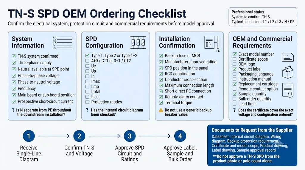
Informasi Kelistrikan
konfirmasi TN-S, pengaturan konduktor, Uo/Un, frekuensi, titik pemasangan, dan arus hubung singkat prospektif.
Konfigurasi SPD
Tipe 1, Tipe 2, atau Tipe 1+2; CT1 atau CT2; Uc, Up, In, Imax, Iimp, Itotal dan perlindungan cadangan.
Persyaratan Komersial
Model yang tepat, kuantitas, persetujuan sampel, logo, label, kemasan, cakupan sertifikat, dan persyaratan modul pengganti.
Templat RFQ SPD TN-S Siap Salin
Ganti informasi di dalam kurung sebelum mengirimkannya ke pemasok.
Aplikasi: [Panel distribusi utama / sub-panel distribusi / panel kontrol]
Sistem pembumian: TN-S
Konduktor suplai: [L1 / L2 / L3 / N / PE]
Tegangan sistem: [___ V fase-ke-fase / ___ V fase-ke-netral]
Frekuensi: [50 / 60 Hz]
Netral tersedia di titik SPD: [Ya / Tidak]
Arus hubung singkat prospektif: [___ kA]

Tipe SPD yang diperlukan: [Tipe 1 / Tipe 2 / Tipe 1+2]
Sirkuit proteksi yang diperlukan: [CT1 / 4+0] atau [CT2 / 3+1]
Uc yang diperlukan: [___ V AC]
Up yang diperlukan: [___ kV]
In / Imax yang diperlukan: [___ kA / ___ kA]
Iimp / Itotal yang diperlukan: [___ kA / ___ kA]
Proteksi cadangan: [Mohon rekomendasikan berdasarkan lembar data yang tepat]

Posisi RCD atau persyaratan proyek: [___]
Indikasi jarak jauh: [Diperlukan / Tidak diperlukan]
Modul yang dapat dipasang (pluggable): [Diperlukan / Opsional]
Sertifikat yang diperlukan: [IEC / EN / TÜV / CB / CE / spesifik proyek]
Logo dan label OEM: [Ya / Tidak]
Bahasa kemasan: [___]
Estimasi kuantitas: [___ unit]
Tanggal pengiriman yang diperlukan: [___]

Mohon sediakan:
1. Nomor model yang tepat
2. Sirkuit proteksi internal
3. Diagram pengkabelan
4. Lembar data
5. Persyaratan proteksi cadangan
6. Sertifikat dan cakupan model
7. Gambar produk dan label
8. Waktu tunggu sampel dan pesanan massal
Perlu mengonfirmasi SPD TN-S sebelum memesan?
Kirimkan diagram satu garis, tegangan sistem, tipe SPD yang diperlukan, tingkat hubung singkat, dan sirkuit proteksi pilihan Anda kepada LEEYEE. Kami dapat membantu mengonfirmasi model, logika pengkabelan, proteksi cadangan, dan persyaratan OEM.
Panduan Teknis Terkait
FAQ Wiring SPD Sistem TN-S
Bisakah SPD 3P digunakan dalam sistem TN-S?
Perangkat ini dapat digunakan jika sirkuit yang dilindungi tidak memiliki konduktor netral atau jika desain proyek yang disetujui secara khusus memerlukan perlindungan tiga kutub. Perangkat ini tidak boleh dipilih secara otomatis untuk panel TN-S lima konduktor.
Apakah SPD 4P sama dengan SPD 3P+N?
Belum tentu. Perangkat 4P sering menggunakan konfigurasi 4+0 / CT1, sedangkan perangkat 3P+N sering menggunakan 3+1 / CT2. Periksa diagram sirkuit internalnya.
Bisakah 4+0 dan 3+1 digunakan dalam sistem TN-S?
Ya, dokumentasi produsen menunjukkan bahwa kedua pengaturan tersebut dapat tersedia untuk sistem TN-S. Pilihan akhir harus disesuaikan dengan proyek, peraturan setempat, dan aplikasi yang disetujui untuk SPD tersebut.
Haruskah SPD dipasang sebelum atau setelah RCD?
Tidak ada jawaban universal untuk setiap SPD. Periksa perilaku TOV produk, teknologi N-PE, posisi yang diizinkan, aturan pemasangan lokal, dan instruksi produsen.
Pemutus arus cadangan apa yang harus digunakan?
Gunakan sekering atau pemutus arus yang ditentukan untuk SPD tersebut setelah memeriksa arus hubung singkat, Isccr, ukuran konduktor, dan koordinasi dengan perlindungan hulu.
Apa yang harus diminta oleh pembeli OEM sebelum memberikan persetujuan?
Minta diagram sirkuit internal, diagram pengabelan, lembar data, persyaratan perlindungan cadangan, cakupan sertifikat, gambar produk, dan gambar label.
Referensi Teknis
- IEC 60364-5-53: Instalasi listrik tegangan rendah — Pemilihan dan pemasangan peralatan listrik. Publikasi resmi IEC.
- IEC 61643-11: Perangkat pelindung lonjakan tegangan rendah yang terhubung ke sistem daya tegangan rendah AC — Persyaratan dan metode pengujian. Publikasi resmi IEC.
- Legrand, Perangkat Pelindung Lonjakan Arus Modular, lembar teknis F04648EN-00. Mencakup mode perlindungan CT1 / X+0 dan CT2 / X+1 serta sistem pembumian yang berlaku. PDF Resmi.
- Legrand, Panduan Teknis Perangkat Pelindung Lonjakan Arus. Menjelaskan sirkuit CT1 dan CT2, komponen N-PE, perilaku TOV, dan koordinasi RCD. PDF Resmi.
- ABB Furse, instruksi pemasangan ESP 240CDT2 untuk pasokan tiga fase TN-S, TN-C-S, dan TT. PDF Resmi.
- Phoenix Contact, panduan pemilihan untuk perlindungan petir dan lonjakan arus pada bangunan industri, termasuk sistem TN-S lima konduktor. PDF Resmi.
- DEHN, Perlindungan Lonjakan Arus pada Rakitan Switchgear Tegangan Rendah. Termasuk solusi SPD modular untuk instalasi TN-S. PDF Resmi.
