
Table des matières
Câblage TN-S SPD en un coup d'œil
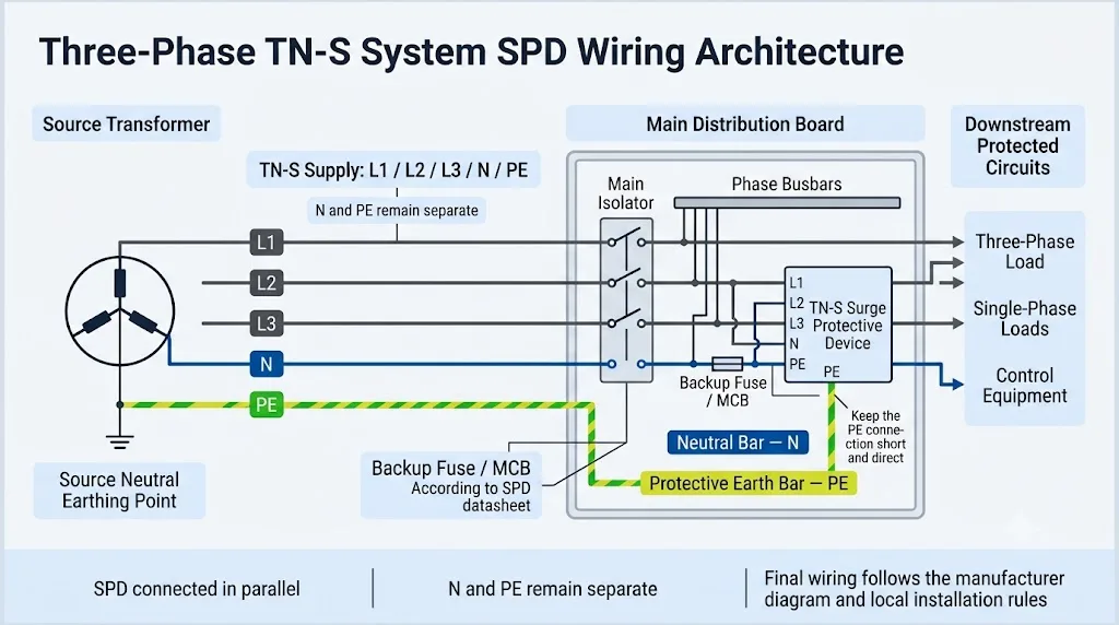
Dans un système TN-S triphasé, le dispositif de protection contre les surtensions est connecté en parallèle avec L1, L2, L3, N et PE selon le circuit interne approuvé du SPD sélectionné. Neutre et terre de protection restent séparés durant le fonctionnement normal.
Réponse rapide : Comment un SPD doit-il être câblé dans un système TN-S ?
Lorsque le neutre est présent, utilisez un agencement 4+0 / CT1 ou 3+1 / CT2 approuvé par le fabricant. Connectez le SPD près des barres collectrices entrantes, utilisez la protection de branche spécifiée et maintenez la connexion SPD-PE aussi courte et directe que possible. Ne choisissez pas le dispositif en fonction du seul nombre de pôles.
Sélection rapide par condition de panneau TN-S
| Condition de panneau TN-S | Direction de sélection commune | Ce que l'acheteur doit confirmer |
|---|---|---|
| L1 / L2 / L3 sans N Circuit triphasé à trois fils | Un SPD 3P spécifique au projet peut être utilisé. | Confirmez que le neutre est réellement absent et vérifiez le schéma de câblage du produit exact. |
| L1 / L2 / L3 / N / PE Le projet spécifie CT1 | 4P / 4+0 / CT1 peut être sélectionné. | Confirmez les modes de protection L-PE et N-PE, Uc, comportement Up, TOV et position RCD autorisée. |
| L1 / L2 / L3 / N / PE Le projet spécifie CT2 | 3P+N / 3+1 / CT2 peut être sélectionné. | Confirmez la protection L-N, le composant N-PE, Itotal, Application TN-S approuvée par le fabricant. |
| La demande ne dit que “ SPD à quatre pôles ” Circuit interne non fourni | Ne pas approuver le modèle pour le moment. | Demander le schéma unifilaire, le circuit SPD interne et les modes de protection requis. |
Les descriptions commerciales “ 4P ” et “ 3P+N ” ne fournissent pas toujours assez d'informations pour confirmer le circuit de protection interne.
Qu'est-ce qu'un système de mise à la terre TN-S ?
Dans un système TN-S, le neutre source est mis à la terre, tandis que le conducteur neutre et le conducteur de terre de protection restent séparés de la source aux charges.
Une alimentation typique TN-S triphasée utilise cinq conducteurs : L1, L2, L3, N et PE. Le neutre transporte le courant de retour normal des charges phase-neutre. Le PE fournit le lien de protection et le chemin du courant de défaut et ne doit pas transporter le courant normal de charge.
Cela diffère du TN-C, où les fonctions neutres et de protection sont combinées dans un conducteur PEN, et du TN-C-S, où un conducteur PEN est séparé en N et PE à un point défini.
Ne pas identifier le TN-S uniquement par les couleurs des conducteurs
Les couleurs peuvent varier selon le pays, l'âge de l'installation et la pratique locale. Confirmez le système à partir du schéma unifilaire du projet, de la documentation d'alimentation et de l'arrangement réel N/PE.
L1, L2, L3, N et PE dans un schéma de câblage TN-S
| Conducteur | Fonction normale | Signification du choix du SPD | Erreur courante |
|---|---|---|---|
| L1 / L2 / L3 Conducteurs de phase | Transportent la tension d'alimentation triphasée et le courant de charge. | Chaque phase nécessite le mode de protection défini par le projet et le circuit SPD. | Choisir un SPD 3P simplement parce que l'alimentation est décrite comme “triphasée.” |
| N Conducteur neutre | Ramené le courant de phase à neutre. | Confirmez si l'appareil fournit une protection L-N, une protection N-PE ou une combinaison des deux. | En supposant que les quatre modules de SPD protègent le neutre de la même manière. |
| PE Terre de protection | Fournit un liaisonnement protecteur et le chemin de décharge de surtension. | Le conducteur SPD-PE doit être court, direct et dimensionné selon les instructions du produit. | Installer le SPD loin de la barre PE et utiliser un conducteur en boucle longue. |
Comment câbler un SPD dans un tableau TN-S triphasé
Le SPD est connecté en parallèle avec l'alimentation entrante. Le courant de charge normal ne passe pas par le SPD.
Confirmez l'agencement de l'alimentation
Vérifiez L1, L2, L3, N et PE à partir du schéma unifilaire et confirmez que le système est TN-S au point d'installation du SPD.
Connectez le SPD en parallèle
Prenez les connexions de phase et de neutre requises à partir des conducteurs ou des barres omnibus entrantes selon le schéma de bornes SPD.
Installez la protection de branche spécifiée
Utilisez le fusible, le disjoncteur miniature ou une autre protection de secours indiquée dans la fiche technique du SPD après avoir vérifié le courant de court-circuit disponible.
Connectez directement à la barre PE
Gardez le chemin de terre court, direct et exempt de boucles ou de courbures inutiles qui augmentent la tension inductive.
Gardez N et PE séparés
Ne pas ajouter de liaison en cuivre permanente entre la barre neutre et la barre PE dans le tableau de distribution TN-S en aval.
Complétez la vérification du panneau
Vérifiez le couple de serrage des bornes, la longueur des fils, la protection de secours, le contact à distance, le module de remplacement et le plan final approuvé.
Les dimensions d'installation sont spécifiques au produit
Ne copiez pas les positions des bornes, les tailles des conducteurs ou les valeurs des dispositifs de sauvegarde depuis un diagramme internet générique. Utilisez les instructions d'installation exactes pour le modèle SPD commandé.
SPD 3P vs 4P vs 3P+N pour un système TN-S
Le nombre de pôles décrit l'agencement physique. Cela ne définit pas complètement les chemins de protection contre les surtensions internes.
| Description du marché | Logique de circuit commun | Utilisation TN-S possible | Confirmation de l'acheteur |
|---|---|---|---|
| SPD 3P Dispositif tripolaire | Protège les conducteurs triphasés sans chemin de neutre dédié. | Un circuit triphasé à trois fils ou un design spécifique approuvé. | Confirmer que le neutre est absent à l'emplacement SPD. |
| 4P SPD Appareil à quatre pôles | Utilise souvent 4+0 / CT1, avec L1, L2, L3 et N protégés vers PE. | Peut convenir si le fabricant approuve l'appareil pour TN-S. | Confirmer le symbole de circuit, les modes de protection, Uc, Up, le comportement TOV et l'arrangement des RCD. |
| 3P+N SPD Trois phases plus neutre | Utilise souvent 3+1 / CT2, avec protection L-N plus un chemin séparé N-PE. | Communément disponible pour les systèmes TN-S. | Confirmez le composant N-PE, Itotal, En haut et le modèle certifié exact. |
Cette page concerne le câblage TN-S, pas seulement la comparaison des produits
Pour une comparaison plus approfondie des structures de produits, consultez le guide SPD 3P+N contre SPD 4P..Cette page TN-S se concentre sur la façon dont le type de système, l'agencement des conducteurs et les conditions d'installation influencent la décision finale de câblage.
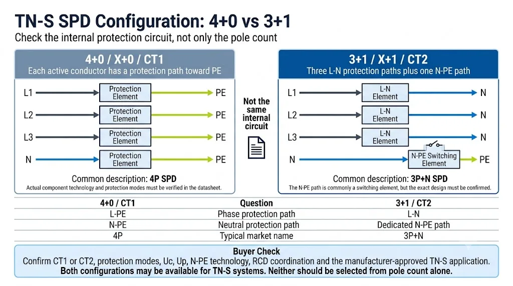
Protection 4+0 vs 3+1 dans un système TN-S
Les deux arrangements de protection peuvent être disponibles pour les systèmes TN-S, mais ils créent des chemins de surtension différents. [3]
| Comparaison | 4+0 / X+0 / CT1 | 3+1 / X+1 / CT2 |
|---|---|---|
| Chemin de protection de phase | Communément L1-PE, L2-PE et L3-PE | Communément L1-N, L2-N et L3-N |
| Chemin de protection neutre | Élément de protection N-PE | Chemin de commutation N-PE dédié |
| Description typique du marché | 4P SPD | 3P+N SPD |
| Vérification principale d'achat | Modes L-PE et N-PE, comportement TOV, Uc, Up et position d'installation | Mode L-N, technologie N-PE, Itotal, Up combiné et position d'installation |
| Peut-il être utilisé en TN-S ? | Oui, lorsque cela est approuvé par le fabricant et la spécification du projet | Oui, lorsque cela est approuvé par le fabricant et la spécification du projet |
Il n'y a pas de gagnant universel
L'arrangement correct dépend de la spécification du projet, du type de SPD, des modes de protection, du niveau de protection contre les surtensions, des performances TOV, de la coordination RCD, du devoir d'intensité du courant d'éclair et de l'application approuvée par le fabricant.
Un système TN-S a-t-il besoin d'une protection contre les surtensions N-PE ?
Lorsque le neutre est présent, l'assemblage de SPD sélectionné nécessite généralement un arrangement de protection contre les surtensions clairement défini lié au neutre. En fonction du circuit, cela peut faire partie d'un design 4+0 / CT1 ou 3+1 / CT2.
Dans un dispositif CT1, N peut avoir un chemin de protection vers PE. Dans un dispositif CT2, la protection de phase fonctionne normalement de L à N, avec un chemin de commutation N-PE séparé. [4]
La protection contre les surtensions N-PE n'est pas une connexion N-PE permanente
L'élément de protection SPD est conçu pour réagir dans des conditions de surtension définies. Cela ne justifie pas l'installation d'un pont permanent neutre-terre dans un tableau TN-S en aval.
Processus de sélection du SPD pour le système TN-S
- Confirmer le système de mise à la terre. Vérifiez que le point de protection est véritablement TN-S et non TN-C-S avant ou après un point de séparation PEN incertain.
- Confirmez l'arrangement des conducteurs. Vérifiez si le neutre est présent à l'emplacement du parafoudre.
- Sélectionnez « Type 1 », « Type 2 » ou « Type 1+2 ». Tenez compte de l'exposition à la foudre, de la protection externe contre la foudre, de l'alimentation électrique et des risques liés au projet — et pas uniquement du système de mise à la terre.
- Vérifiez CT1 ou CT2. Consultez le schéma de circuit interne et le tableau des modes de protection.
- Vérifiez les valeurs nominales de tension et de décharge. Vérifier les valeurs de Uc, Up, In, Imax, Iimp et Itotal le cas échéant.
- Vérifier la coordination en cas de court-circuit. Vérifier l'Isccr, le courant de court-circuit prévisionnel et la protection de secours autorisée.
- Vérifiez la position de montage. Vérifier les longueurs des conducteurs, la coordination des disjoncteurs différentiels, le raccordement du conducteur de protection et la disposition du tableau électrique.
- Vérifiez la portée exacte du certificat. Vérifiez que le modèle, la tension et la configuration commandés sont bien pris en charge.
Paramètres à confirmer avant de commander
| Paramètres | Pourquoi c'est important | Question de l’acheteur |
|---|---|---|
| Uo / UnTension du système | Définit les tensions normales phase-neutre et phase-phase. | Le système fonctionne-t-il en 230/400 V, 240/415 V ou à une autre tension ? |
| UcTension continue maximale | Doit être adapté à la tension continue et aux conditions d'exploitation prévues du système. | L'UC est-elle homologuée pour ce système TN-S précis et ce marché ? |
| Haut de la pageNiveau de protection de la tension | Indique les performances limites dans les conditions d'essai définies. | Quels sont les niveaux de protection L-N, L-PE et N-PE applicables ? |
| Dans / ImaxCaractéristiques de décharge de type 2 | Décrivez les caractéristiques nominales et maximales en matière de courant d'impulsion. | Les valeurs nominales indiquées s'appliquent-elles par mode, par pôle ou à l'ensemble ? |
| IimpCourant d'impulsion de type 1 | Obligatoire lorsque l'on prévoit une charge due aux courants de foudre. | Quelle est la valeur de l'Iimp par mode et pour l'ensemble multipôle complet ? |
| ItotalCourant de décharge total | Important pour les appareils multipolaires de type 1 et les voies de décharge N-PE. | Le circuit N-PE est-il capable de supporter le courant total requis ? |
| Isccr / IscRésistance aux courts-circuits | Il faut tenir compte du courant de défaut disponible au niveau du tableau électrique. | Quelle protection de secours est requise au niveau de défaillance indiqué ? |
| CT1 / CT2Circuit de protection | Définit les chemins de protection internes. | Le fournisseur peut-il fournir le schéma électrique interne ? |
| Contact à distanceSignalisation d'état | Permet la surveillance via un automate programmable (PLC), un système de gestion technique du bâtiment (BMS) ou des systèmes d'alarme. | Quelles sont les caractéristiques logiques NO/NC et les caractéristiques des contacts ? |
La norme CEI 61643-11 définit les exigences et les méthodes d'essai applicables aux dispositifs de protection contre les surtensions (SPD) raccordés à des réseaux électriques à basse tension en courant alternatif. L'installation et le choix de ces dispositifs doivent également respecter les exigences applicables en matière d'installations électriques. [1] [2]
Position du DDR et protection de secours du SPD
Le choix de la coordination du disjoncteur différentiel ne peut pas se faire uniquement sur la base des mentions « CT1 » ou « CT2 ». Vérifiez le comportement TOV du disjoncteur différentiel, la technologie N-PE, la position d'installation autorisée ainsi que les instructions de câblage précises du fabricant.
Certains produits sont soumis à des exigences spécifiques concernant leur installation en amont ou en aval d'un disjoncteur différentiel. Leur emplacement définitif doit également être conforme aux règles d'installation locales et aux spécifications du projet. [4]
Ne pas installer un disjoncteur de secours universel
Le fusible ou le disjoncteur de secours doit être choisi à partir de la fiche technique du SPD après avoir vérifié la protection de secours maximale autorisée, la section du conducteur, le courant de court-circuit prévisible et la sélectivité.
- Vérifiez la protection de secours maximale autorisée par le fabricant.
- Vérifiez le courant de court-circuit prévisionnel au point d'installation.
- Confirmez l'Isccr ou l'agencement de coordination de court-circuit indiqué.
- Vérifier la sélectivité avec les dispositifs de protection en amont.
- Vérifier les moyens d'isolation et d'accès pour la maintenance requis.
Erreurs courantes de câblage et de sélection de SPD TN-S
- On choisit le 3P uniquement parce que l'alimentation est triphasée. Un tableau TN-S comportant des charges raccordées au neutre peut nécessiter un circuit de protection lié au neutre.
- Considérer 4P et 3P+N comme identiques. Des modules comportant le même nombre de composants peuvent intégrer des circuits de protection différents.
- Description des chemins L-PE sous la forme d'un circuit classique 3+1. Une configuration CT2 classique utilise généralement des circuits L-N ainsi qu'un circuit N-PE.
- Rebrancher les conducteurs N et PE en aval. Dans une installation de type TN-S, le neutre et la terre de protection doivent rester séparés.
- Utilisation de conducteurs SPD longs. L'inductance ajoutée augmente la tension effective perçue par l'équipement protégé.
- En utilisant une classification générique des périphériques de sauvegarde. La protection de secours doit correspondre exactement au SPD et au niveau de défaut du tableau.
- Sélectionner uniquement le type 1 ou le type 2 dans le système de mise à la terre. Le type de SPD dépend de l'exposition à la foudre, de l'alimentation électrique et du niveau d'installation.
- Vérification de Imax uniquement. Uc, Up, In, Iimp, Itotal, l'Isccr et les modes de protection ont également leur importance.
- Valider un certificat sans vérifier le champ d'application du modèle. Vérifiez que la tension et la configuration indiquées dans le certificat sont exactes.
Liste de contrôle de commande OEM et en gros pour SPD TN-S
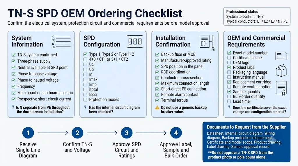
Veuillez nous envoyer toutes les informations relatives au système et au projet avant de demander un devis pour un modèle définitif, un échantillon ou une commande en gros.
Informations électriques
Confirmation du schéma TN-S, disposition des conducteurs, Uo/Un, fréquence, point d'installation et courant de court-circuit prévisionnel.
Configuration des SPD
Type 1, Type 2 ou Type 1+2 ; CT1 ou CT2 ; Uc, Up, In, Imax, Iimp, Itotal et la protection par sauvegarde.
Exigences commerciales
Modèle exact, quantité, validation de l'échantillon, logo, étiquette, emballage, portée du certificat et exigences relatives aux modules de remplacement.
Modèle de demande de devis (RFQ) TN-S prêt à l'emploi
Remplacez les informations entre crochets avant d'envoyer le document au fournisseur.
Application : [Tableau de distribution principal / tableau de dérivation / tableau de commande]
Système de mise à la terre : TN-S
Conducteurs d'alimentation : [L1 / L2 / L3 / N / PE]
Tension du réseau : [___ V phase-phase / ___ V phase-neutre]
Fréquence : [50 / 60 Hz]
Neutre disponible au point du parafoudre : [Oui / Non]
Courant de court-circuit prévisionnel : [___ kA]

Type de parafoudre requis : [Type 1 / Type 2 / Type 1+2]
Circuit de protection requis : [CT1 / 4+0] ou [CT2 / 3+1]
Uc requis : [___ V CA]
Up requis : [___ kV]
In / Imax requis : [___ kA / ___ kA]
Iimp / Itotal requis : [___ kA / ___ kA]
Protection de secours : [Veuillez faire une recommandation à partir de la fiche technique exacte]

Emplacement du disjoncteur différentiel ou exigence du projet : [___]
Signalisation à distance : [Requis / Non requis]
Module enfichable : [Requis / En option]
Certificat requis : [CEI / EN / TÜV / CB / CE / spécifique au projet]
Logo et étiquette OEM : [Oui / Non]
Langue de l'emballage : [___]
Quantité estimée : [___ unités]
Date de livraison requise : [___]

Veuillez fournir :
1. Le numéro de modèle exact
2. Le circuit de protection interne
3. Le schéma de câblage
4. La fiche technique
5. Les exigences en matière de protection de secours
6. Le certificat et le champ d'application du modèle
7. Le dessin du produit et de l'étiquette
8. Le délai de livraison pour les échantillons et les commandes en gros
Besoin de confirmer un SPD TN-S avant de commander ?
Envoyez à LEEYEE votre schéma unifilaire, la tension du système, le type de SPD requis, le niveau de court-circuit et le circuit de protection souhaité. Nous pouvons vous aider à valider le modèle, la logique de câblage, la protection de secours et les exigences des équipementiers.
Guides techniques connexes
FAQ sur le câblage SPD du système TN-S
Un SPD triphasé peut-il être utilisé dans un réseau TN-S ?
Il peut être utilisé lorsque le circuit protégé ne comporte pas de conducteur neutre ou lorsque la conception approuvée du projet exige expressément une protection tripolaire . Il ne doit pas être choisi systématiquement pour un tableau électrique à cinq conducteurs de type TN-S.
Un SPD 4P est-il identique à un SPD 3P+N ?
Pas forcément. Un appareil 4P utilise souvent une configuration 4+0 / CT1, tandis qu'un appareil 3P+N utilise souvent une configuration 3+1 / CT2. Vérifiez le schéma de câblage interne.
Les configurations 4+0 et 3+1 peuvent-elles toutes deux être utilisées dans un système TN-S ?
Oui, la documentation du fabricant indique que ces deux configurations peuvent être utilisées dans les systèmes TN-S. Le choix final doit tenir compte du projet, de la réglementation locale et de l’application homologuée du dispositif de protection contre les surtensions (SPD) concerné.
Le SPD doit-il être installé avant ou après le RCD ?
Il n'existe pas de réponse universelle valable pour tous les SPD. Vérifiez le comportement TOV du produit, la technologie N-PE, les positions autorisées, les règles d'installation locales et les instructions du fabricant.
Quel disjoncteur de secours faut-il utiliser ?
Utilisez le fusible ou le disjoncteur prévu pour le SPD concerné après avoir vérifié le courant de court-circuit (Isccr), la section des conducteurs et la coordination avec la protection en amont.
Que doit demander un acheteur OEM avant de donner son accord ?
Demandez le schéma de circuit interne, le schéma de câblage, la fiche technique, les exigences en matière de protection de secours, le champ d'application du certificat, le plan du produit et le plan de l'étiquette.
Références techniques
- IEC 60364-5-53 : Installations électriques à basse tension — Choix et mise en place des équipements électriques. Publication officielle de la CEI.
- CEI 61643-11 : Parafoudres basse tension connectés aux réseaux de distribution basse tension — Exigences et méthodes d'essai. Publication officielle de la CEI.
- Legrand, Dispositifs modulaires de protection contre les surtensions, fiche technique F04648EN-00. Comprend les modes de protection CT1 / X+0 et CT2 / X+1 ainsi que les systèmes de mise à la terre applicables. PDF officiel.
- Legrand, Guide technique sur les dispositifs de protection contre les surtensions. Présente les circuits CT1 et CT2, les composants N-PE, le comportement TOV et la coordination des disjoncteurs différentiels. PDF officiel.
- ABB Furse, notice d'installation de l'ESP 240CDT2 pour les alimentations triphasées TN-S, TN-C-S et TT. PDF officiel.
- Phoenix Contact, guide de sélection pour la protection contre la foudre et les surtensions dans les bâtiments industriels, y compris les installations TN-S à cinq conducteurs. PDF officiel.
- DEHN, Protection contre les surtensions dans les ensembles d'appareillage basse tension. Comprend des solutions modulaires de protection contre les surtensions (SPD) pour les installations TN-S. PDF officiel.
