
Questo guida al diagramma di cablaggio del protettore da sovratensione monofase spiega come i costruttori di quadri dovrebbero collegare 1P+N e 2P SPDs, identificare i terminali L, N e PE, coordinare la protezione di backup, posizionare l'SPD rispetto a un RCD e rivedere gli schemi di messa a terra TT o TN-S.
Indice dei contenuti
Come si collega un SPD in un quadro di distribuzione monofase?
In un tipico quadro di distribuzione monofase, l'SPD è collegato in parallelo. Il collegamento L viene prelevato dalla fornitura in entrata o dal busbar e instradato attraverso il MCB di backup o il fusibile specificato quando necessario. Il collegamento N va al punto neutro designato o alla barra neutra. Il collegamento PE va direttamente alla barra di terra utilizzando il conduttore più corto possibile.
Il diagramma esatto cambia in base alla topologia interna del SPD, al sistema di messa a terra e alla disposizione del RCD. Un SPD 1P+N e un SPD 2P non dovrebbero essere trattati come automaticamente intercambiabili.
Questi diagrammi spiegano la logica tipica del design dei pannelli. L'installazione finale, la dimensione del conduttore, la protezione di backup e le connessioni dei terminali devono seguire le istruzioni del produttore SPD selezionato, il disegno approvato del pannello, le norme applicabili e le regole elettriche locali.
Come leggere un diagramma di cablaggio SPD monofase
Un diagramma di cablaggio SPD monofase dovrebbe mostrare due percorsi elettrici diversi: il percorso di corrente normale e il percorso di deviazione della corrente di sovratensione.
Durante il normale funzionamento, la corrente attraversa l'interruttore principale, l'RCD o l'RCBO, gli interruttori in uscita e i carichi. Normalmente non passa attraverso l' SPD come se l'SPD fosse un interruttore automatico collegato in serie.
Durante una sovratensione transitoria, l'SPD crea temporaneamente un percorso a bassa impedenza e devia la corrente di sovratensione attraverso il relativo modo di protezione L-N, L-PE o N-PE.
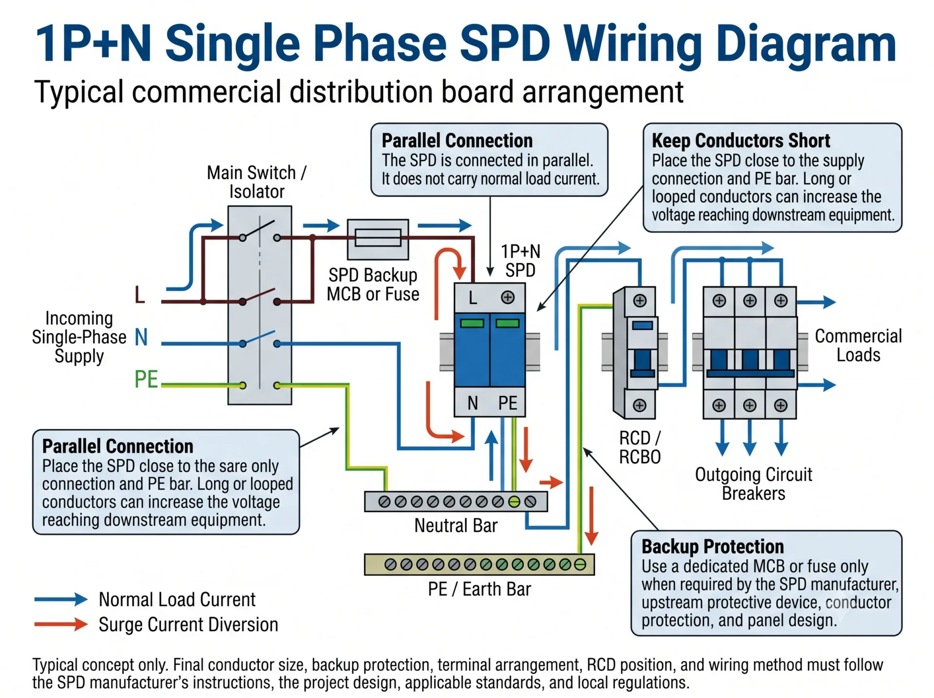
Punto di design del pannello: Uno schema può essere elettricamente corretto ma fornire comunque una scarsa protezione reale se lo SPD è montato lontano dal punto di alimentazione o dalla barra PE.
Diagramma di cablaggio SPD monofase 1P+N
Un tipico SPD 1P+N combina una funzione di protezione legata alla fase con una funzione di protezione dedicata legata al neutro. Un comune schema utilizza un percorso di limitazione della tensione L-N e un percorso di commutazione della tensione N-PE.
Sequenza di connessione tipica 1P+N
- Prendere il ramo SPD dalla connessione di alimentazione in arrivo o dalla barra.
- Fornire il ramo attivo attraverso l'MCB di backup specificato o il fusibile quando è richiesta una protezione di backup separata.
- Collegare il terminale L al ramo attivo mostrato nello schema prodotto.
- Collegare il terminale N al punto di connessione neutra designato.
- Collegare il terminale PE o la connessione a terra direttamente alla barra PE.
- Mantenere tutti e tre i percorsi di collegamento brevi ed evitare loop non necessari.
Importante: La marcatura 1P+N non dimostra che ogni produttore utilizzi lo stesso MOV, GDT, gap di scintilla o disposizione dei terminali. Controllare il simbolo del circuito stampato sul prodotto o mostrato nella sua documentazione tecnica.
Diagramma di cablaggio SPD monofase 2P
Un SPD 2P fornisce tipicamente due poli protetti per i conduttori attivi e neutri. In un comune schema, L e N hanno entrambi un percorso di protezione verso PE. Altri prodotti 2P possono utilizzare un circuito interno diverso.
Esternamente, il conduttore attivo si collega al polo L, il conduttore neutro si collega al polo N e la connessione a terra dello SPD si collega alla barra PE. Il carico rimane connesso attraverso il circuito di distribuzione normale piuttosto che attraverso lo SPD.
| Conduttore o connessione | Connessione tipica | Cosa deve essere controllato |
|---|---|---|
| L | Alimentazione in arrivo o barra al polo attivo dello SPD. | Uc, protezione di backup e marcatura del terminale. |
| N | Punto di connessione neutro o barra neutra al polo neutro dello SPD. | Se il polo neutro è protetto verso PE o attraverso un altro modo interno. |
| PE | Terminale di terra SPD alla barra PE. | Percorso del conduttore corto e diretto. |
| Circuito di carico | Continua attraverso l'interruttore principale normale, RCD e dispositivi di protezione in uscita. | Lo SPD rimane collegato in parallelo. |
Un involucro 2P non prova una topologia interna 2+0. Rivedere i modi di protezione L-N, L-PE e N-PE effettivi prima di sostituire un dispositivo 1P+N o di approvare un modello OEM.
1P+N vs 2P SPD: perché il solo conteggio dei poli non è sufficiente
I termini 1P+N, 2P, 1+1 e 2+0 descrivono idee correlate, ma non sempre descrivono lo stesso circuito di protezione interno. Il conteggio dei moduli fisici non è sufficiente per identificare i modi di protezione.
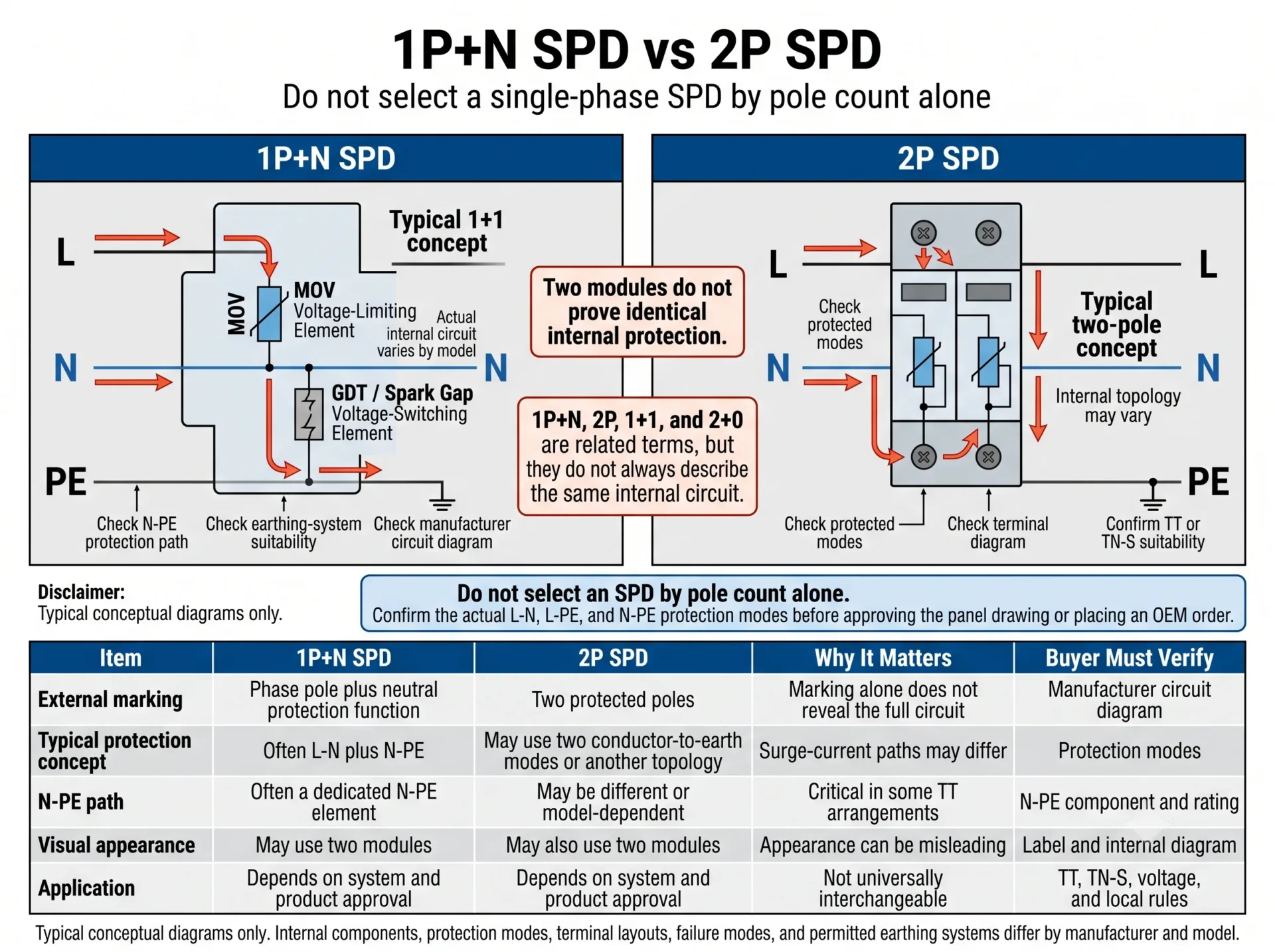
| Marcatura | Cosa può descrivere | Perché è importante | Cosa verificare |
|---|---|---|---|
| 1P+N | Protezione della fase più una funzione di protezione correlata al neutro. | Il percorso N-PE può utilizzare un componente diverso da quello del percorso di fase. | Circuito interno, elemento N-PE, Uc e idoneità del sistema di messa a terra. |
| 2P | Due poli protetti o due canali. | Non equivale automaticamente a un dispositivo 1P+N. | Modi protetti, diagramma dei terminali e applicazione approvata. |
| 1+1 | Spesso una modalità di limitazione della tensione più una modalità di commutazione della tensione. | Il percorso della corrente di sovratensione e il comportamento in caso di guasto possono differire. | Componenti effettivi e sistema di messa a terra consentito. |
| 2+0 | Spesso due modalità di limitazione della tensione conduttore-terra. | Non è un sostituto universale per un'installazione 1+1. | Comportamento di sovratensione temporanea, topologia e requisiti locali. |
| Due moduli | Solo aspetto fisico. | SPDs dall'aspetto simile possono utilizzare circuiti diversi. | Diagramma laterale, scheda dati e conferma del produttore. |
Dove dovrebbero essere collegati L, N e PE?
L — Conduttore di fase
Collegare il conduttore di fase dal punto di alimentazione designato al terminale L dell'SPD. Ove richiesto, instradare questa derivazione attraverso l'interruttore magnetotermico (MCB) o il fusibile di backup coordinato.
N — Conduttore neutro
Collegare il terminale neutro al punto di neutro o alla barra di neutro designati. Verificare se il prodotto utilizza una configurazione di protezione L-N, N-PE o combinata.
PE — Terra di protezione
Collegare il percorso di messa a terra dell'SPD direttamente alla barra PE. Il conduttore deve essere corto, rettilineo e privo di anelli non necessari.
Separazione tra N e PE
Non creare un collegamento neutro-terra non autorizzato all'interno del quadro a valle. Le relazioni tra neutro e PE sono determinate dal sistema di messa a terra e dal progetto del quadro approvato.
Un SPD monofase ha bisogno di un MCB o di un fusibile dedicato?
È richiesto un interruttore magnetotermico (MCB) o un fusibile separato quando specificato dal produttore dell'SPD, quando il dispositivo di protezione a monte supera il massimo consentito, quando i conduttori di derivazione necessitano di una protezione separata o quando la progettazione del quadro richiede un mezzo di sezionamento dedicato.
Non selezionare l'MCB di backup basandosi direttamente sul valore In o Imax dell'SPD. In e Imax descrivono le prestazioni rispetto alle correnti di sovratensione, non la portata nominale del dispositivo di protezione da sovracorrente standard.
Leggere la scheda tecnica e le istruzioni di installazione dell'SPD selezionato.
Determinare se la protezione a monte esistente soddisfa già il limite di coordinamento del produttore.
L'SPD e il dispositivo di protezione devono essere idonei al livello di guasto nel punto di installazione.
La sezione trasversale del conduttore, il percorso e il metodo di installazione influenzano la decisione relativa alla protezione.
Un interruttore magnetotermico (MCB) separato può supportare l'isolamento e la sostituzione, ma la disposizione finale deve essere conforme allo standard del quadro.
L'SPD dovrebbe essere installato prima o dopo l'RCD?
In molti quadri monofase commerciali, l'SPD viene installato a monte dei circuiti finali protetti da interruttori differenziali (RCD) o magnetotermici differenziali (RCBO). Ciò contribuisce a evitare che l'intero percorso della corrente di sovratensione attraversi ciascun dispositivo a corrente residua a valle.
Laddove venga utilizzato un interruttore differenziale principale in ingresso, in particolare in un sistema TT, la posizione finale dell'SPD deve essere riesaminata unitamente al tipo di RCD, all'immunità alle correnti di sovratensione, alla disposizione del neutro e alla topologia dell'SPD selezionata.
| Disposizione del quadro | Posizione tipica dell'SPD | Principale aspetto progettuale |
|---|---|---|
| Circuiti terminali RCBO a valle | Solitamente a monte degli RCBO del circuito finale. | Evitare di instradare il percorso della corrente di sovratensione attraverso ogni dispositivo a corrente residua a valle. |
| RCD di ingresso principale | Specifico per il progetto. | Immunità alle sovratensioni dell'RCD, selettività, topologia dell'SPD e sistema di messa a terra. |
| SPD a valle di un RCD | Solo laddove l'RCD e l'SPD siano adeguatamente coordinati. | Possibili scatti intempestivi e resistenza dell'RCD alle correnti impulsive. |
| Sistema TT | Dipende dall'architettura dell'RCD e dal tipo di connessione selezionato. | Percorso di protezione N-PE, coordinamento RCD e normative locali sul cablaggio. |
| TN-S con RCD a valle | Solitamente a monte dei circuiti protetti da RCD a valle. | Percorso PE breve, topologia corretta e schema del produttore. |
Regola pratica: Per prima cosa, identificare se l'RCD è il dispositivo di ingresso principale o un dispositivo a valle del circuito finale. Successivamente, verificare il sistema di messa a terra e le modalità di protezione SPD prima di stabilire la posizione dell'SPD.
Cablaggio di SPD monofase nei sistemi TT vs TN-S
I sistemi TT e TN-S mantengono entrambi il neutro e la terra di protezione separati nel quadro a valle, ma l'origine del percorso di terra di protezione è diversa. Tale differenza influenza il percorso di sovratensione, la protezione N-PE e il coordinamento dell'RCD.
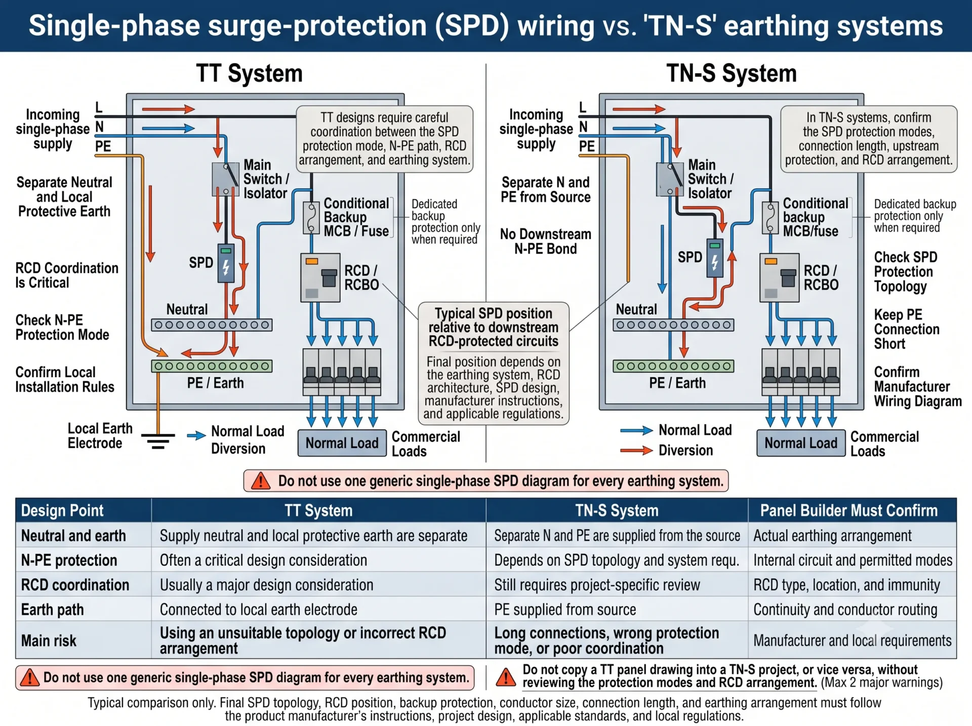
| Punto di progettazione | Sistema TT | Sistema TN-S | Il costruttore del quadro deve confermare |
|---|---|---|---|
| Neutro e terra | Il neutro di alimentazione e il sistema di messa a terra di protezione locale sono separati. | I conduttori N e PE sono forniti separatamente dalla sorgente. | Disposizione di messa a terra effettiva e schema unifilare approvato. |
| protezione N-PE | Spesso una parte critica della topologia selezionata. | Dipende dal design del prodotto e del sistema. | Circuito interno e modalità di protezione consentite. |
| Coordinazione RCD | Solitamente una considerazione progettuale di primaria importanza. | Ancora richiesto laddove siano installati RCD principali o a valle. | Tipo, posizione, immunità e instradamento del neutro dell'RCD. |
| Percorso della corrente di terra | Deviato verso il sistema PE locale e l'elettrodo di terra. | Deviato verso il conduttore PE fornito. | Continuità, lunghezza del conduttore e posizione della barra PE. |
| Principale rischio di errore | Topologia N-PE errata o scarso coordinamento dell'RCD. | Modalità di protezione errata o lunghezza eccessiva dei conduttori. | Compatibilità tra prodotto e progetto. |
Perché la lunghezza del conduttore SPD cambia il livello di protezione installato
Il valore Up in una scheda tecnica viene misurato in condizioni di prova definite. In un quadro di distribuzione reale, i conduttori di collegamento L, N e PE aggiungono una tensione induttiva durante una sovratensione rapida.
Sollecitazione approssimativa dell'apparecchiatura = Up dell'SPD + tensione aggiunta dai conduttori di collegamento.
Ecco perché la disposizione del quadro è importante. Un SPD ben selezionato, installato con conduttori lunghi o ad anello, può fornire una protezione reale inferiore alle aspettative.
- Posizionare l'SPD vicino alla connessione di alimentazione in ingresso.
- Mantenere il collegamento PE breve e diretto.
- Evitare ampi anelli e piegature inutili dei conduttori.
- Non posizionare l'SPD all'estremità remota della guida DIN solo per comodità.
- Utilizzare il cablaggio a V o passante solo quando i morsetti e le istruzioni del produttore lo consentono.
- Laddove non sia possibile realizzare collegamenti brevi, valutare l'installazione di una protezione coordinata contro le sovratensioni a valle.
Errori comuni nel cablaggio di SPD monofase
La corrente di carico nominale non deve passare attraverso l'SPD.
Due moduli non dimostrano che due SPD utilizzino la stessa topologia interna.
Il coordinamento tra messa a terra e RCD deve essere esaminato separatamente.
Imax non determina direttamente la taratura dell'interruttore magnetotermico di backup.
Un percorso di terra lungo aumenta la tensione durante un transitorio rapido.
Il neutro e il conduttore di protezione devono seguire lo schema di messa a terra approvato.
Non copiare "sempre prima" o "sempre dopo" in ogni progetto.
L'SPD e la protezione di backup devono corrispondere al livello di guasto dell'installazione.
Checklist per SPD monofase per costruttori di quadri
Confermare questi dettagli prima di rilasciare un disegno o effettuare un ordine OEM:
Riepilogo del cablaggio di SPD monofase
- Collegare l'SPD in parallelo, non in serie al carico.
- Collegare L dall'alimentazione o dalla sbarra collettrice, N al punto neutro designato e PE direttamente alla barra di terra.
- Verificare se il prodotto è effettivamente 1P+N, 2P, 1+1 o 2+0 consultando il relativo schema elettrico interno.
- Selezionare l'interruttore magnetotermico (MCB) o il fusibile di backup in base ai dati di coordinamento del produttore, alla protezione a monte e alle condizioni di corrente di guasto.
- In molti quadri, l'SPD si trova a monte dei circuiti protetti da RCD a valle, ma le configurazioni con RCD principale e i sistemi TT richiedono un'ulteriore analisi.
- Mantenere i collegamenti L, N e PE brevi, poiché l'induttanza dei conduttori aumenta la tensione che raggiunge l'apparecchiatura.
Hai bisogno di aiuto per confermare un modello di SPD monofase?
Inviateci la tensione del vostro sistema, il tipo di messa a terra, lo schema del quadro, la protezione a monte e la posizione dell'RCD. LEEYEE può aiutarvi a definire una configurazione SPD idonea per quadri di distribuzione commerciali, pannelli OEM e ordini all'ingrosso.
Domande frequenti
Come è cablato un SPD in un quadro di distribuzione monofase?
L'SPD è solitamente collegato in parallelo. L si collega dall'alimentazione o dalla barra collettrice tramite una protezione di riserva, se richiesta, N si collega al punto neutro designato e PE si collega direttamente alla barra di terra.
È un SPD monofase collegato in serie o parallelo?
È solitamente collegato in parallelo. La corrente di carico normale non attraversa l'SPD.
Qual è la differenza tra il cablaggio SPD 1P+N e 2P?
Un SPD 1P+N utilizza spesso una funzione di protezione dedicata per il neutro, mentre un SPD 2P fornisce due poli o canali protetti. Le modalità interne esatte devono essere verificate sullo schema del prodotto.
Può un SPD 2P sostituire un SPD 1P+N?
Non automaticamente. Verificare prima le modalità di protezione L-N, L-PE e N-PE, i valori nominali Uc, l'idoneità del sistema di messa a terra e la protezione di riserva.
È necessario un MCB separato per uno SPD monofase?
Dipende dal valore massimo di protezione di backup del produttore, dal dispositivo a monte, dalla protezione del conduttore di derivazione e dalla corrente di cortocircuito nel punto di installazione.
L'SPD deve essere installato prima o dopo il RCD?
Viene solitamente installato a monte dei circuiti finali protetti da RCD o RCBO. Gli RCD principali in ingresso e le configurazioni TT richiedono un coordinamento specifico per il progetto.
Dove dovrebbe essere collegato il filo di terra SPD?
Collegarlo direttamente alla barra di terra o PE designata seguendo il percorso del conduttore più breve possibile.
Possono i sistemi TT e TN-S utilizzare lo stesso schema di cablaggio SPD?
Non devono essere considerati automaticamente identici. Il percorso di protezione N-PE, il percorso della corrente di terra e il coordinamento dell'RCD devono essere verificati per il sistema specifico.
Quanto devono essere corti i conduttori di collegamento SPD?
Mantenere i percorsi quanto più brevi e diretti possibile. Il percorso completo, incluse le curve e il collegamento PE, influisce sul livello di protezione installato.
L'Imax determina la valutazione del MCB di backup?
No. Imax è un parametro relativo alla corrente di scarica. La protezione di riserva viene selezionata in base ai dati di coordinamento del produttore, alla protezione a monte, alla protezione dei conduttori e alle condizioni di corrente di guasto.
Riferimenti Tecnici
- IEC 61643-11 — Dispositivi di protezione contro le sovratensioni a bassa tensione per sistemi di alimentazione in corrente alternata: requisiti e metodi di prova.
- IEC 61643-12 — Dispositivi di protezione contro le sovratensioni a bassa tensione: principi di selezione e applicazione.
- IEC 60364-5-53 — Scelta e installazione dei componenti elettrici: sezionamento, manovra e comando.
- Istruzioni di installazione del produttore e dati di coordinamento per il modello di SPD selezionato.
- Normative nazionali applicabili in materia di cablaggio e documentazione di progetto approvata.
