
This single phase surge protector wiring diagram guide explains how panel builders should connect 1P+N and 2P SPDs, identify L, N and PE terminals, coordinate backup protection, position the SPD relative to an RCD, and review TT or TN-S earthing arrangements.
Table of Contents
How do you wire an SPD in a single-phase distribution board?
In a typical single-phase distribution board, the SPD is connected in parallel. The L connection is taken from the incoming supply or busbar and routed through the specified backup MCB or fuse when required. The N connection goes to the designated neutral point or neutral bar. The PE connection goes directly to the earth bar using the shortest practical conductor.
The exact diagram changes with the SPD’s internal topology, the earthing system and the RCD arrangement. A 1P+N SPD and a 2P SPD should not be treated as automatically interchangeable.
These diagrams explain typical panel-design logic. Final installation, conductor size, backup protection and terminal connections must follow the selected SPD manufacturer’s instructions, the approved panel drawing, applicable standards and local electrical rules.
How to Read a Single Phase SPD Wiring Diagram
A single phase SPD wiring diagram should show two different electrical paths: the normal load-current path and the surge-current diversion path.
During normal operation, current flows through the main switch, RCD or RCBO, outgoing breakers and loads. It does not normally pass through the SPD as if the SPD were a series-connected circuit breaker.
During a transient overvoltage, the SPD temporarily creates a lower- impedance path and diverts surge current through the relevant L-N, L-PE or N-PE protection mode.
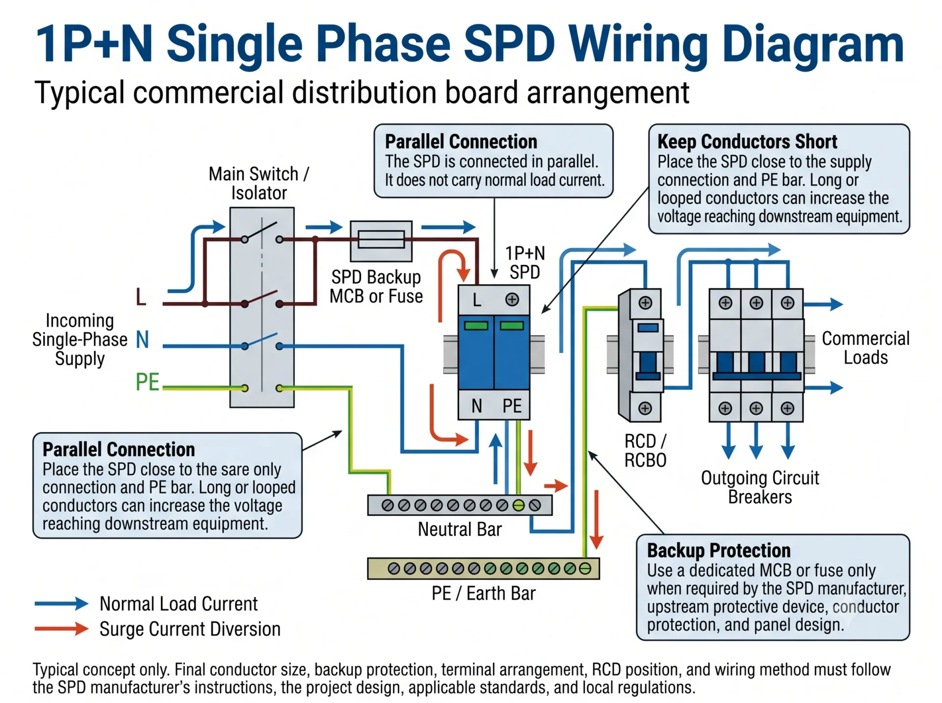
Panel-design point: A schematic can be electrically correct but still provide poor real protection if the SPD is mounted far from the supply point or PE bar.
1P+N Single Phase SPD Wiring Diagram
A typical 1P+N SPD combines a phase-related protection function with a dedicated neutral-related protection function. One common arrangement uses an L-N voltage-limiting path and an N-PE voltage-switching path.
Typical 1P+N connection sequence
- Take the SPD branch from the incoming supply connection or busbar.
- Route the live branch through the specified backup MCB or fuse when separate backup protection is required.
- Connect the L terminal to the live branch shown in the product diagram.
- Connect the N terminal to the designated neutral connection point.
- Connect the PE terminal or earth connection directly to the PE bar.
- Keep all three connecting paths short and avoid unnecessary loops.
Important: The 1P+N marking does not prove that every manufacturer uses the same MOV, GDT, spark-gap or terminal arrangement. Check the circuit symbol printed on the product or shown in its technical documentation.
2P Single Phase SPD Wiring Diagram
A 2P SPD typically provides two protected poles for the live and neutral conductors. In one common arrangement, L and N each have a protection path toward PE. Other 2P products may use a different internal circuit.
Externally, the live conductor connects to the L pole, the neutral conductor connects to the N pole, and the SPD earth connection connects to the PE bar. The load remains connected through the normal distribution circuit rather than through the SPD.
| Conductor or connection | Typical connection | What must be checked |
|---|---|---|
| L | Incoming supply or busbar to the SPD live pole. | Uc, backup protection and terminal marking. |
| N | Neutral connection point or neutral bar to the SPD neutral pole. | Whether the neutral pole is protected toward PE or through another internal mode. |
| PE | SPD earth terminal to the PE bar. | Short and direct conductor path. |
| Load circuit | Continues through the normal main switch, RCD and outgoing protective devices. | The SPD remains parallel-connected. |
A 2P enclosure does not prove a 2+0 internal topology. Review the actual L-N, L-PE and N-PE protection modes before replacing a 1P+N device or approving an OEM model.
1P+N vs 2P SPD: Why Pole Count Alone Is Not Enough
The terms 1P+N, 2P, 1+1 and 2+0 describe related ideas, but they do not always describe the same internal protection circuit. Physical module count is not enough to identify the protection modes.
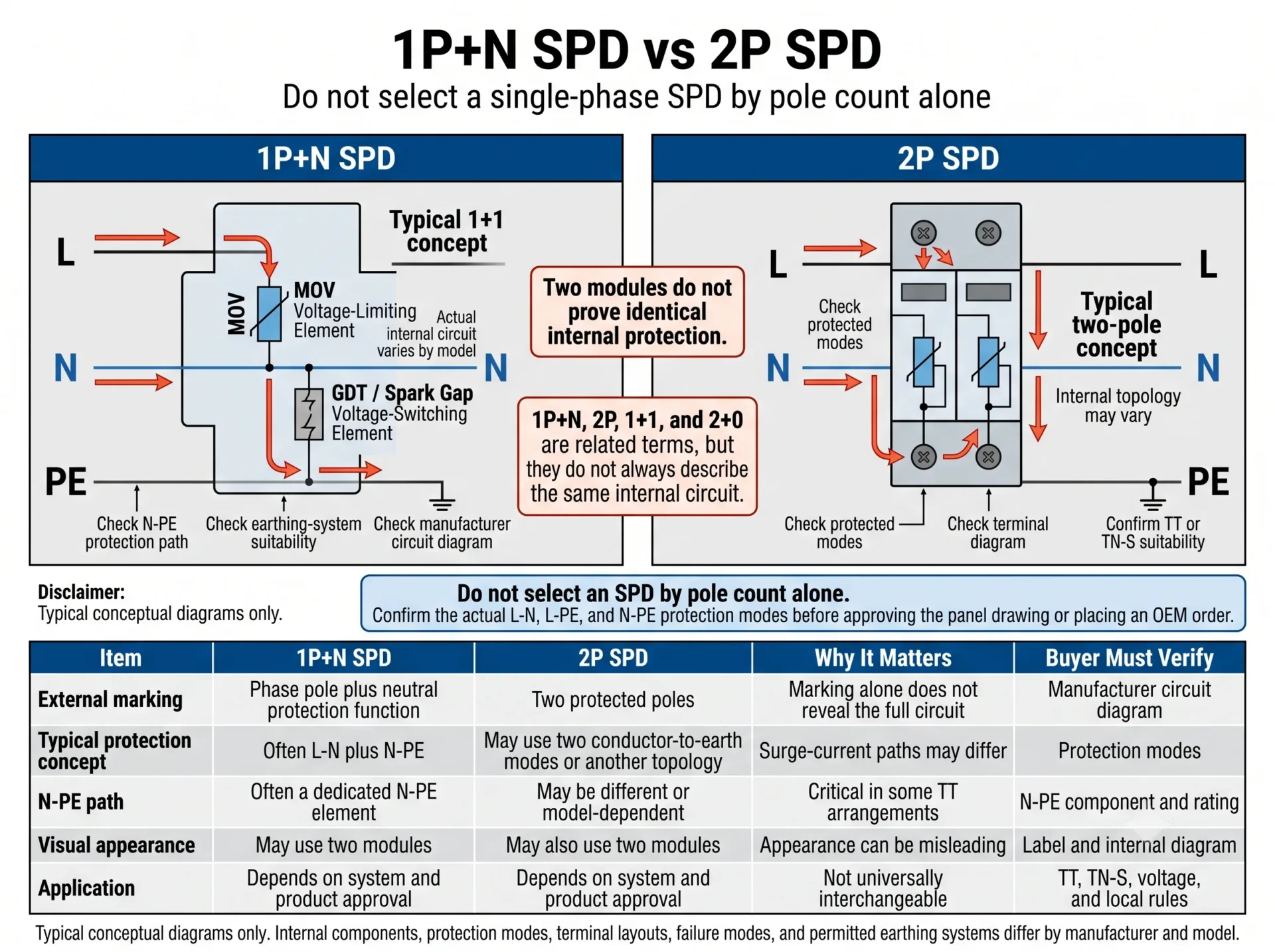
| Marking | What it may describe | Why it matters | What to verify |
|---|---|---|---|
| 1P+N | Phase protection plus a neutral-related protection function. | The N-PE path may use a different component from the phase path. | Internal circuit, N-PE element, Uc and earthing-system suitability. |
| 2P | Two protected poles or two channels. | It does not automatically equal a 1P+N device. | Protected modes, terminal diagram and approved application. |
| 1+1 | Often one voltage-limiting mode plus one voltage-switching mode. | Surge-current path and failure behavior can differ. | Actual components and permitted earthing system. |
| 2+0 | Often two conductor-to-earth voltage-limiting modes. | It is not a universal substitute for a 1+1 arrangement. | Temporary overvoltage behavior, topology and local requirements. |
| Two modules | Physical appearance only. | Similar-looking SPDs may use different circuits. | Side diagram, datasheet and manufacturer confirmation. |
Where Should L, N and PE Be Connected?
L — Live conductor
Connect the live conductor from the designated supply point to the SPD L terminal. Where required, route this branch through the coordinated backup MCB or fuse.
N — Neutral conductor
Connect the neutral terminal to the designated neutral point or neutral bar. Check whether the product uses an L-N, N-PE or combined protection arrangement.
PE — Protective earth
Connect the SPD earth path directly to the PE bar. The conductor should be short, straight and free from unnecessary loops.
N and PE separation
Do not create an unauthorized neutral-to-earth bond inside the downstream board. Neutral and PE relationships are determined by the earthing system and approved panel design.
Does a Single-Phase SPD Need a Dedicated MCB or Fuse?
A separate MCB or fuse is required when the SPD manufacturer specifies one, when the upstream protective device exceeds the permitted maximum, when the branch conductors need separate protection, or when the panel design requires a dedicated means of disconnection.
Do not select the backup MCB directly from the SPD’s In or Imax value. In and Imax describe surge-current performance, not the normal overcurrent-device rating.
Read the selected SPD datasheet and installation instruction.
Determine whether the existing upstream protection already satisfies the manufacturer’s coordination limit.
The SPD and protective arrangement must be suitable for the fault level at the installation point.
Conductor cross-section, route and installation method influence the protection decision.
A separate MCB can support isolation and replacement, but the final arrangement must match the panel standard.
Should the SPD Be Installed Before or After the RCD?
In many commercial single-phase boards, the SPD is installed upstream of downstream RCD- or RCBO-protected final circuits. This helps prevent the full surge-current path from passing through each downstream residual-current device.
Where a main incomer RCD is used, particularly in a TT system, the final SPD position must be reviewed together with the RCD type, surge-current immunity, neutral arrangement and selected SPD topology.
| Panel arrangement | Typical SPD position | Main design concern |
|---|---|---|
| Downstream RCBO final circuits | Commonly upstream of the final-circuit RCBOs. | Avoid routing the surge-current path through every downstream residual-current device. |
| Main incomer RCD | Project-specific. | RCD surge immunity, selectivity, SPD topology and earthing system. |
| SPD downstream of an RCD | Only where the RCD and SPD are suitably coordinated. | Possible nuisance tripping and the RCD’s impulse-current withstand. |
| TT system | Depends on the RCD architecture and selected connection type. | N-PE protection path, RCD coordination and local wiring rules. |
| TN-S with downstream RCDs | Commonly upstream of the downstream RCD-protected circuits. | Short PE route, correct topology and manufacturer diagram. |
Practical rule: First identify whether the RCD is the main incomer device or a downstream final-circuit device. Then review the earthing system and SPD protection modes before fixing the SPD position.
Single-Phase SPD Wiring in TT vs TN-S Systems
TT and TN-S systems both keep neutral and protective earth separate in the downstream board, but the origin of the protective-earth path is different. That difference influences the surge path, N-PE protection and RCD coordination.
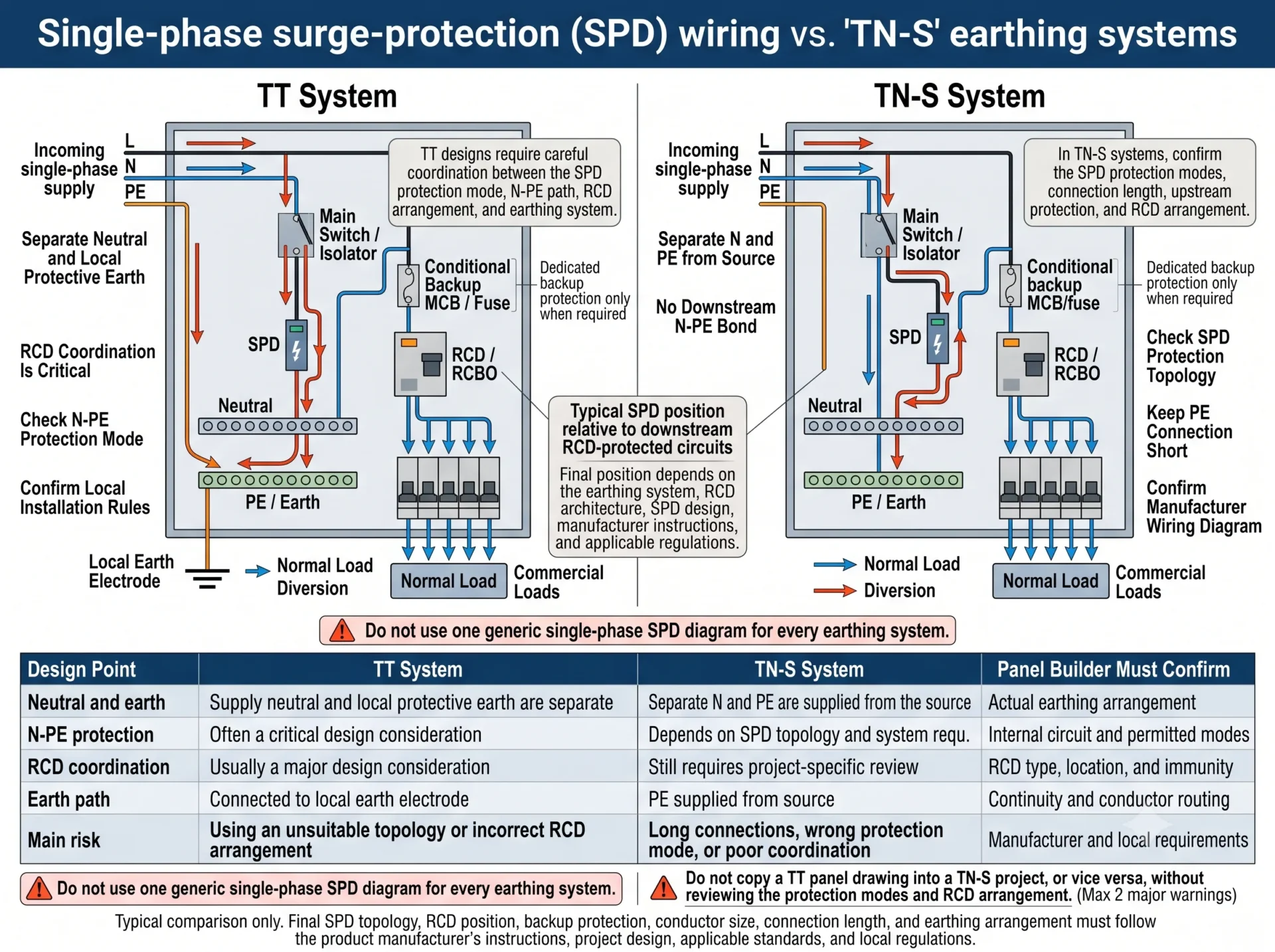
| Design point | TT system | TN-S system | Panel builder must confirm |
|---|---|---|---|
| Neutral and earth | Supply neutral and the local protective-earth system are separate. | Separate N and PE conductors are supplied from the source. | Actual earthing arrangement and approved single-line diagram. |
| N-PE protection | Often a critical part of the selected topology. | Depends on the product and system design. | Internal circuit and permitted protection modes. |
| RCD coordination | Usually a major design consideration. | Still required where main or downstream RCDs are installed. | RCD type, position, immunity and neutral routing. |
| Earth-current path | Diverted toward the local PE system and earth electrode. | Diverted toward the supplied PE conductor. | Continuity, conductor length and PE-bar location. |
| Main error risk | Wrong N-PE topology or poor RCD coordination. | Wrong protection mode or excessive conductor length. | Product and project compatibility. |
Why SPD Conductor Length Changes the Installed Protection Level
The Up value in a datasheet is measured under defined test conditions. In a real distribution board, the L, N and PE connecting conductors add inductive voltage during a fast surge.
Approximate equipment stress = SPD Up + voltage added by the connecting conductors.
This is why panel layout matters. A well-selected SPD installed with long or looped conductors may provide worse real protection than expected.
- Place the SPD close to the incoming supply connection.
- Keep the PE connection short and direct.
- Avoid large loops and unnecessary conductor bends.
- Do not place the SPD at the remote end of the DIN rail only for convenience.
- Use V-type or through-wiring only when the terminals and manufacturer instructions permit it.
- Where short connections are impossible, review coordinated downstream surge protection.
Common Single-Phase SPD Wiring Mistakes
Normal load current should not pass through the SPD.
Two modules do not prove that two SPDs use the same internal topology.
Earthing and RCD coordination must be reviewed separately.
Imax does not directly determine the backup MCB rating.
A long earth path adds voltage during a fast transient.
Neutral and PE must follow the approved earthing arrangement.
Do not copy “always before” or “always after” into every project.
The SPD and backup protection must match the installation fault level.
Single-Phase SPD Checklist for Panel Builders
Confirm these details before releasing a drawing or placing an OEM order:
Single Phase SPD Wiring Summary
- Connect the SPD in parallel, not in series with the load.
- Connect L from the supply or busbar, N to the designated neutral point, and PE directly to the earth bar.
- Confirm whether the product is truly 1P+N, 2P, 1+1 or 2+0 from its internal circuit diagram.
- Select the backup MCB or fuse from manufacturer coordination data, upstream protection and fault-current conditions.
- In many boards, the SPD is upstream of downstream RCD-protected circuits, but main-RCD and TT arrangements require additional review.
- Keep the L, N and PE connections short because conductor inductance increases the voltage reaching the equipment.
Need Help Confirming a Single-Phase SPD Model?
Send us your system voltage, earthing arrangement, panel diagram, upstream protection and RCD position. LEEYEE can help confirm a suitable SPD configuration for commercial distribution boards, OEM panels and bulk orders.
Frequently Asked Questions
How is an SPD wired in a single-phase distribution board?
The SPD is normally connected in parallel. L connects from the supply or busbar through backup protection when required, N connects to the designated neutral point, and PE connects directly to the earth bar.
Is a single-phase SPD connected in series or parallel?
It is normally connected in parallel. Normal load current does not pass through the SPD.
What is the difference between 1P+N and 2P SPD wiring?
A 1P+N SPD often uses a dedicated neutral-related protection function, while a 2P SPD provides two protected poles or channels. The exact internal modes must be checked from the product diagram.
Can a 2P SPD replace a 1P+N SPD?
Not automatically. Confirm the L-N, L-PE and N-PE protection modes, Uc ratings, earthing-system suitability and backup protection first.
Does a single-phase SPD need a separate MCB?
It depends on the manufacturer’s maximum backup-protection value, upstream device, branch conductor protection and short-circuit current at the installation point.
Should the SPD be installed before or after the RCD?
It is commonly installed upstream of downstream RCD- or RCBO- protected final circuits. Main incomer RCD and TT arrangements require project-specific coordination.
Where should the SPD earth wire be connected?
Connect it directly to the designated PE or earth bar with the shortest practical conductor route.
Can TT and TN-S systems use the same SPD wiring diagram?
They should not be treated as automatically identical. The N-PE protection path, earth-current route and RCD coordination must be reviewed for the actual system.
How short should SPD connecting conductors be?
Keep them as short and direct as practical. The complete route, including bends and the PE connection, affects the installed protection level.
Does Imax determine the backup MCB rating?
No. Imax is a surge-current parameter. Backup protection is selected from manufacturer coordination data, upstream protection, conductor protection and fault-current conditions.
Technical References
- IEC 61643-11 — Low-voltage surge protective devices for AC power systems: requirements and test methods.
- IEC 61643-12 — Low-voltage surge protective devices: selection and application principles.
- IEC 60364-5-53 — Selection and erection of electrical equipment: isolation, switching and control.
- Manufacturer installation instructions and coordination data for the selected SPD model.
- Applicable national wiring regulations and approved project documentation.
