
Mechanical and electrical interlocking protect different parts of an automatic transfer switch transfer sequence. In a conventional open-transition ATS, the objective is to disconnect one source before connecting the other and prevent an unintended simultaneous connection of the two power sources.[1][2]
For panel builders, generator integrators and OEM buyers, the useful question is not simply whether a supplier says an ATS has “double interlock.” The real questions are: what blocks an invalid physical switch position, what prevents a conflicting electrical command, and how can those functions be verified before sample or bulk approval?
Mechanical interlock acts on the switching mechanism and restricts incompatible physical positions. Electrical interlock acts on the control or operating circuit and prevents conflicting commands. The ATS controller monitors the sources and determines when a transfer should be initiated according to the equipment's configured logic.[3]
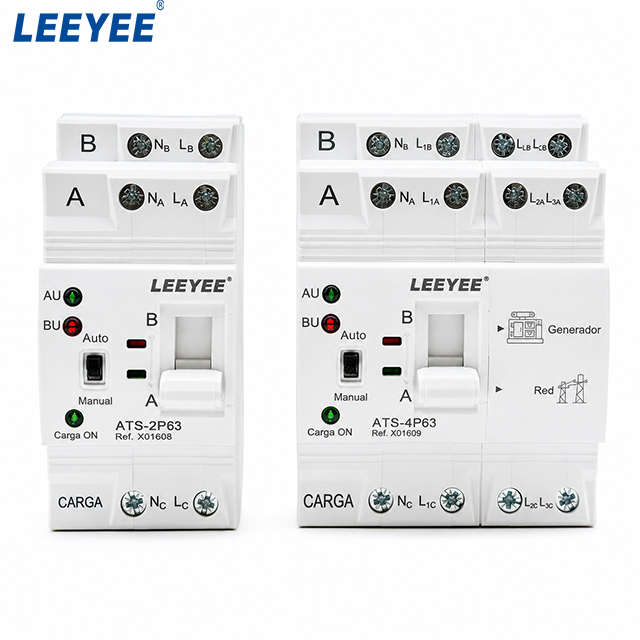
- 2P and 4P compact ATS formats;
- A and B source positions;
- Auto / Manual selection;
- manual operating handle;
- source and load terminal areas;
- grid / generator identification on the 4P unit shown.
- internal mechanical interlock construction;
- electrical interlock circuit;
- position-feedback method;
- model-specific switching sequence;
- applicable compliance and test scope.
Indice dei contenuti
What Does an ATS Interlock Actually Prevent?
A transfer switch connects a load between two supply sources. In open-transition operation, the first source is disconnected before the second source is connected. Eaton describes this operating principle as break-before-make.[2]
This source separation matters because two independent AC sources should not be unintentionally paralleled. Their voltage magnitude, phase angle and frequency may not match. Closed-transition equipment is specifically engineered to manage controlled overlap; conventional open-transition equipment should not be treated as if it has that capability.[1][4]
For an open-transition ATS, the key question is which source states are permitted during normal operation.
| Normal Source | Backup Source | Significato ingegneristico |
|---|---|---|
| Closed | Open | Load supplied by the normal source. |
| Open | Open | Open-transfer interval or neutral position where provided by the design. |
| Open | Closed | Load supplied by the backup source. |
| Closed | Closed | Not a normal permitted state for conventional open-transition operation. |
Procurement conclusion: identify the transition type first. “Both sources closed” has a very different meaning in conventional open-transition equipment and purpose-designed closed-transition equipment.
Mechanical Interlock: The Physical Safety Layer
A mechanical interlock uses the physical transfer mechanism to restrict incompatible switching positions. Its implementation depends on the ATS architecture. It may use a dedicated interlock between separate switching devices, a common double-throw mechanism, a linkage, a cam or another manufacturer-designed arrangement.
Eaton documents open-transition transfer-switch designs in which the switching devices are mechanically and electrically interlocked so that the two main contact sets cannot close simultaneously.[4] ABB also describes motorized change-over switches with an inbuilt mechanical interlock intended to maintain separation between two asynchronous supplies.[5]
The important point is that mechanical interlock describes a function, not one universal component. A compact integrated transfer switch does not have to look like two large contactors connected by an external locking bar.
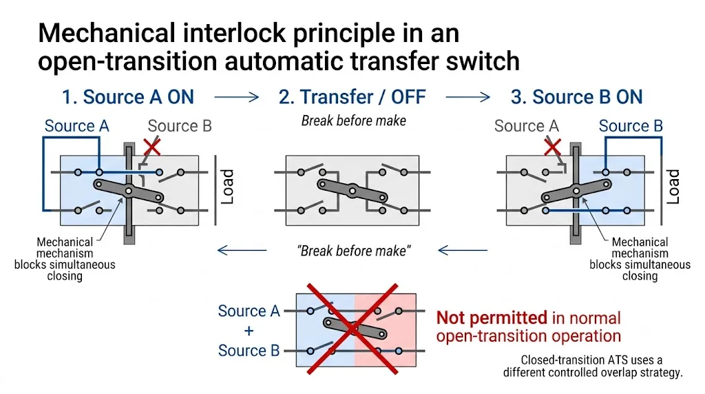
Mechanical interlocking provides a physical restriction in the switching mechanism. It should not be confused with controller software. However, its exact construction, permitted positions and manual operating behaviour remain model-specific and require project confirmation.
Electrical Interlock: The Command Safety Layer
Electrical interlocking works in the control or operating circuit. Its purpose is to prevent a conflicting close command from being completed when the opposite switching state makes that command invalid.
In a contactor-based ATS, one common implementation is cross-interlocking through auxiliary contacts. ABB publishes contactor-based ATS examples using two contactors, auxiliary contact blocks and mechanical interlock components as part of the transfer arrangement.[6]
Other ATS architectures can achieve the same control objective through relays, limit switches, position feedback, electronics or manufacturer-specific actuator logic. Buyers should therefore avoid assuming that every ATS uses one standard relay circuit.
Typical Electrical Interlock Logic in an Open-Transition ATS
The exact circuit depends on the product design, but the control objective can be summarised simply: the alternate source should not receive a valid closing command until the opposite source has reached the required open state and the remaining transfer conditions are satisfied.
| Detected Switch State | Typical Control Result | Perché è importante |
|---|---|---|
| Source A closed | Source B close command inhibited. | Prevents a conflicting closing command. |
| Source A confirmed open | Source B may be permitted to close if the remaining transfer conditions are satisfied. | Supports break-before-make transfer. |
| Source B closed | Source A close command inhibited. | Prevents the opposite conflicting command. |
| Source B confirmed open | Source A may be permitted to close if the remaining retransfer conditions are satisfied. | Allows a controlled return to the preferred source. |
This table describes the control objective of a typical open-transition electrical interlock. It is not the internal wiring diagram of every ATS. Voltage conditions, delays, source availability and other permissives can also affect whether a close command is accepted.
Mechanical vs Electrical Interlock in an Automatic Transfer Switch
The key comparison is not which interlock is “better,” but where each function acts.
| Decision Point | Mechanical Interlock | Electrical Interlock |
|---|---|---|
| Acts on | Physical switching mechanism or contact system. | Control, actuator or command circuit. |
| Scopo principale | Restrict an incompatible physical position. | Block or inhibit a conflicting operating command. |
| Typical implementation | Common mechanism, linkage, cam or dedicated interlock. | Auxiliary contacts, relays, feedback or electronic logic. |
| Manual operation | Can continue to restrict physical movement where the design provides it. | Behaviour depends on how the control circuit is isolated or bypassed. |
| Verifica dell'acquirente | Check permitted positions and the mechanical transfer sequence. | Check the control diagram, feedback and command-inhibition logic. |
These are functional descriptions. The exact interlocking method must be confirmed against the manufacturer's documentation for the selected ATS model.
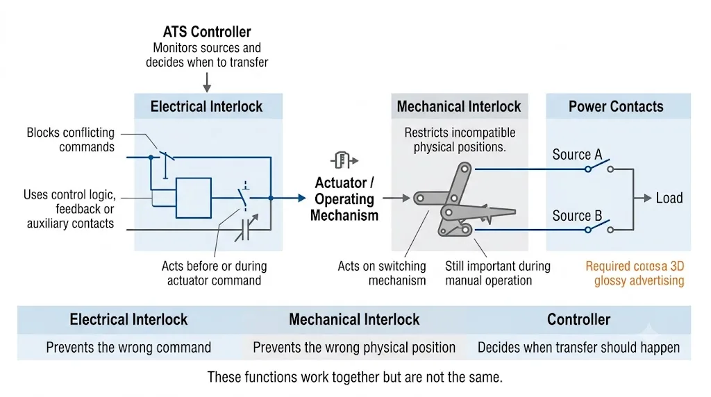
Controller, Electrical Interlock and Mechanical Interlock Are Different Layers
ATS specifications often become confusing because controller logic and interlocking are described together. Separating them into three functional layers makes the transfer sequence easier to evaluate.
- The controller monitors the sources. In automatic mode, the controller evaluates the available sources according to the monitoring functions and settings provided by the equipment.[2]
- The controller initiates the required transfer. A transfer begins when the configured operating conditions are met.
- The electrical operating circuit permits or blocks commands. Depending on the architecture, feedback, auxiliary contacts, relays or electronic logic may prevent a conflicting command from being completed.
- The operating mechanism changes the contact position. In open transition, the existing source connection is broken before the alternate source connection is made.[2]
- The mechanical construction restricts incompatible positions. Where a mechanical interlock is part of the design, it provides a physical layer independent of the controller's transfer decision.
Contactor-Type ATS and Compact Switch-Type ATS Do Not Use the Same Interlock Structure
This distinction matters because many ATS interlock diagrams show a contactor-based arrangement and then present it as if it represented every automatic transfer switch.
Contactor-Based ATS
In a contactor-based arrangement, two contactors can serve as the two switching devices. A dedicated mechanical interlock can physically link the contactors, while auxiliary contacts and relay logic can provide electrical cross-interlocking.
ABB's application note provides a useful example because it shows actual contactor-based ATS circuits together with auxiliary contacts and mechanical interlock components.[6]
Compact Switch-Type ATS
The LEEYEE product shown near the beginning of this guide uses a compact integrated format rather than the appearance of two large externally interlocked contactors. The front panel provides visible A/B positions together with Auto/Manual operation and a manual handle.
On the 4P unit shown in the product image, the markings identify Source A as the grid side e Source B as the generator side. This statement applies to the configuration visible in that product image and should not be assumed to define every ATS configuration without checking the model documentation.
For this type of compact ATS, buyers should not copy a two-contactor interlock circuit onto the product or assume that an external locking bar must be visible. The exact internal switching and interlocking construction should be confirmed from the technical documentation for the selected model.
LEEYEE ATS-63 is a compact DIN-rail automatic transfer switch for switching between two AC sources. Current product data lists 2P and 4P versions, rated current options from 6A to 63A, AC110V / AC220V / AC400V variants, 50/60Hz operation, PC Class and AC-31B utilisation category.[7]
These values describe the current ATS-63 range. They do not by themselves prove a specific internal interlock construction. For project approval, confirm the exact model's switching sequence, wiring instructions and applicable compliance documents.
Why Manual Operation Is an Important Interlock Check
Manual operation is especially relevant to this compact ATS format because the front panel provides both an Auto/Manual selector and a manual operating handle. That makes manual transfer behaviour a practical item to check during sample approval.
When automatic controller logic is not governing the transfer in the normal way, the permitted physical positions of the mechanism become more visible to the operator. In equipment that uses a mechanical interlock, the physical restriction can remain relevant during manual operation.[8]
The exact behaviour remains model-specific. A buyer should not force the handle beyond its permitted travel or infer internal contact position only from the front appearance.
With the equipment safely isolated and following the manufacturer's instructions, operate the front handle through its permitted A/B transfer positions. Confirm that the visible position indication follows the intended transfer sequence and that normal manual operation does not permit an unintended dual-source state.
What Can Go Wrong If Interlocking Is Poor or Damaged?
“Interlock failure” is not one single fault. Mechanical damage, incorrect control wiring, defective position feedback and controller faults can produce different symptoms and different risks.
A reliable design should support
- repeatable source transfer;
- defined permitted positions;
- clear position indication;
- controlled operating commands;
- safe manual operation;
- a documented transfer sequence.
Conditions that require investigation
- uncertain contact position;
- conflicting actuator commands;
- incomplete transfer;
- mechanism jamming or abnormal wear;
- incorrect position feedback;
- unexpected source connection.
The actual consequence depends on the ATS architecture and system conditions. Do not diagnose a field problem from these symptoms alone. Isolate the equipment safely and follow the manufacturer's service procedure.
Do Not Confuse Interlocking With Other ATS Functions
Several ATS functions affect transfer behaviour, but they do not automatically prove that a mechanical or electrical interlock is present.
| ATS Function | What It Does | Why It Is Different From Interlocking |
|---|---|---|
| Auto / Manual selector | Changes how operation is initiated. | It does not by itself prove which physical positions the mechanism permits. |
| Voltage monitoring | Determines whether source conditions satisfy the controller's settings. | Monitoring decides whether transfer may be needed; it does not mechanically separate the contacts. |
| Transfer delay | Controls when transfer occurs. | A time delay is not a physical interlock. |
| Source indication | Shows source availability or switching status. | An indication alone does not prevent an incompatible physical position. |
| Fuse / circuit breaker | Provides overcurrent or short-circuit protection according to its design. | Protection devices and transfer interlocking perform different functions. |
Procurement conclusion: verify transfer logic, interlocking and overcurrent protection separately. Do not treat one feature as evidence for another.
Open Transition and Closed Transition Must Not Be Mixed Up
Open transition is break-before-make: the first source connection is broken before the second source connection is made.[2]
Closed transition is make-before-break. Eaton describes closed transition as connecting the second source before disconnecting the first, while the sources must satisfy the equipment's synchronising requirements before the intentional overlap occurs.[2][4]
IEC 60947-6-1:2026 includes dedicated requirements for ATSE with closed-transition capability.[1]
Which Standard Should a Buyer Check?
The current international edition of IEC 60947-6-1 is IEC 60947-6-1:2026, Edizione 4.0. It covers low-voltage transfer switching equipment, including automatically operated transfer switching equipment and additional transfer-switch configurations defined by the standard.[1]
For procurement, the important point is to verify the documentation of the complete ATS being purchased rather than assuming that a controller, contactor or individual switching component alone proves the performance or compliance of the complete transfer assembly.
How Should a B2B Buyer Verify ATS Interlocking?
A useful supplier review turns the word “interlock” into specific items that can be checked on a drawing, sample or operating procedure.
- 1. What transition method does this exact model use? Confirm whether the equipment is open transition, closed transition or another manufacturer-defined transfer type.
- 2. What prevents an incompatible physical source position? Ask the supplier to identify the mechanical principle instead of accepting only “yes, it has interlock.”
- 3. How are conflicting electrical commands inhibited? Ask whether the design uses auxiliary contacts, position feedback, relays, electronics or another defined method.
- 4. What changes in manual mode? Verify the permitted positions and the manufacturer's required operating procedure.
- 5. How is the actual switching position detected or indicated? Distinguish source-available indication from actual mechanism or contact-position indication.
- 6. Which documents apply to the exact model? Request the current datasheet, wiring instructions, operating instructions and project-required compliance documents.
ATS Interlock Checklist Before Sample or OEM Approval
- Tensione del sistema: confirm the actual AC system voltage.
- Frequency: confirm 50Hz or 60Hz requirements.
- Corrente nominale: confirm load current and relevant starting or inrush conditions.
- Poli: confirm whether 2P or 4P switching is required by the system design.
- Source types: identify utility, generator, inverter or other AC sources.
- Transition method: confirm the required open- or closed-transition behaviour.
- Mechanical sequence: review which positions are physically possible.
- Electrical interlock: review how conflicting commands are inhibited.
- Manual operation: confirm the safe operating procedure and permitted positions.
- Position feedback: confirm how actual transfer position is indicated or reported.
- Protezione a monte: coordinate the ATS with the required overcurrent and short-circuit protection.
- Project documents: verify the exact model, wiring diagram and applicable compliance scope.
- OEM approval: keep the approved sample, technical file and production configuration aligned.
This checklist is more useful than asking only, “Does this ATS have mechanical and electrical interlock?” A simple yes/no answer does not tell a panel builder how source exclusivity is actually maintained.
Need to Confirm an ATS Configuration?
Send the system voltage, rated current, required poles, normal and backup source type, load information and required project documents. LEEYEE can help review whether the available ATS-63 configuration matches the electrical and installation requirements before sample or OEM approval.
Domande frequenti
What is a mechanical interlock in an automatic transfer switch?
A mechanical interlock is a physical feature of the switching mechanism that restricts incompatible source positions. In conventional open-transition equipment, it can help prevent the two source switching devices from being closed together unintentionally.[4]
What is an electrical interlock in an ATS?
Electrical interlocking prevents or inhibits conflicting operating commands through the control circuit. Depending on the ATS architecture, the design can use auxiliary contacts, position feedback, relays or electronic control logic.
Why use both mechanical and electrical interlocking?
They act at different layers. Electrical interlocking addresses the operating command, while mechanical interlocking addresses the physical switching position. Some open-transition transfer-switch designs document both functions.[4]
Does every ATS use two mechanically interlocked contactors?
No. Contactor-based ATS is only one architecture. Transfer equipment can also use switch-based or breaker-based mechanisms. ABB's contactor application note is one implementation example, not a universal internal ATS design.[6]
Is mechanical interlocking still important during manual operation?
It can be. In designs where a mechanical interlock physically restricts the switching devices, that restriction can remain relevant during manual operation. The exact behaviour must be checked in the operating instructions for the selected model.[8]
Can both ATS sources ever be connected at the same time?
Not as an unintended operating state in a conventional open-transition ATS. Purpose-designed closed-transition ATSE is different because it can intentionally overlap the two sources under defined and controlled conditions.[1][2]
Is an Auto/Manual selector the same as an interlock?
No. Auto/Manual selects how operation is initiated. It does not by itself prove how the power contacts are mechanically restricted or how conflicting electrical commands are blocked.
How should an OEM buyer verify ATS interlocking?
Review the transition type, switching mechanism, permitted manual positions, control diagram, position feedback and applicable model documentation. Then verify the operating sequence on the approved sample using the manufacturer's safe operating procedure.
Does a fast transfer time prove that an ATS has reliable interlocking?
No. Transfer time describes timing. Interlocking describes how conflicting commands or incompatible switching positions are prevented. They should be evaluated as separate technical characteristics.
Riferimenti
- International Electrotechnical Commission (IEC). IEC 60947-6-1:2026 — Apparecchiature di commutazione e controllo a bassa tensione — Parte 6-1: Apparecchiature multifunzionali — Apparecchiature di commutazione di trasferimento. Edition 4.0. Pagina delle pubblicazioni ufficiali dell’IEC.
- Eaton. Automatic Transfer Switches (ATS) Fundamentals. Technical guidance covering open transition, closed transition, ATS operating modes and switching mechanisms. Linee guida tecniche Eaton.
- Eaton. Automatic Transfer Switch Controllers and Remote Annunciators Design Guide. Guidance covering ATS controller functions and transfer operation. Eaton design guide.
- Eaton. Automatic Transfer Switch, Bypass Isolation, Contactor Type, Open/Closed Transition — Operation and Maintenance Manual. Technical documentation describing open-transition interlocking and closed-transition operating differences. Eaton operation and maintenance manual.
- ABB. Motorized Transfer Switches. Product information covering motorized change-over switching equipment and inbuilt mechanical interlocking. ABB product information.
- ABB. Contactor-Based Automatic Transfer Switch Solutions — Application Note, document 1SAC200128W0001. Includes example ATS circuits using contactors, auxiliary contacts and mechanical interlock components. ABB application note.
- LEEYEE. ATS-63 Automatic Transfer Switch Technical Data. Current product information covering rated current, voltage, poles, frequency, PC Class, AC-31B utilisation category, transfer switching time and DIN-rail installation. Pagina del prodotto LEEYEE ATS-63.
- Eaton. Automatic Transfer Switch Operation Documentation. Manufacturer documentation describing manual operation and mechanical interlocking in an open-transition transfer-switch design. Eaton instruction booklet.
Final project suitability depends on the exact ATS model, source arrangement, transition requirement, wiring method, protection coordination and applicable local or project requirements. Confirm uncertain conditions against the current model documentation before engineering approval or bulk ordering.
