
SPD a spinterometro vs SPD a varistore (MOV) non è un semplice confronto tra "migliore o peggiore". Uno spinterometro utilizza un comportamento di commutazione della tensione. Un MOV utilizza un comportamento di limitazione della tensione. Questa guida spiega come tali strutture influenzano la selezione di Tipo 1, Tipo 1+2, N-PE e 3+1 per l'approvvigionamento tecnico e l'approvazione OEM.
Indice dei contenuti
Risposta Veloce
A SPD basato su spinterometro rimane isolato elettricamente durante il normale funzionamento e passa a un percorso di scarica a bassa impedenza quando viene raggiunta la sua condizione di innesco.
Un SPD basato su varistore (MOV) riduce progressivamente la propria resistenza all'aumentare della tensione, deviando la corrente di sovratensione e limitando al contempo la tensione sul circuito protetto.
Gli spinterometri sono ampiamente utilizzati per le funzioni di corrente di fulmine di Tipo 1 e N-PE. I MOV dominano la protezione di Tipo 2 e sono impiegati anche in configurazioni testate di Tipo 1+2. Il Tipo 1 è una classificazione di prova per dispositivi completi, non il nome di un componente.
Regola di approvvigionamento: confrontare Iimp, Uc, Up, modalità di protezione, comportamento della corrente susseguente, Isccr, protezione di riserva e il modello certificato esatto.
La norma IEC 61643-11:2025 riguarda gli SPD collegati ai sistemi di alimentazione a bassa tensione in corrente alternata e viene utilizzata in combinazione con la norma IEC 61643-01:2024. I certificati esistenti potrebbero ancora fare riferimento all'edizione del 2011; pertanto, gli acquirenti sono tenuti a verificare l'edizione applicabile, l'adozione nazionale e l'ambito preciso del certificato.[1][2]
SPD a spinterometro vs SPD a varistore (MOV)
La tabella descrive il comportamento ingegneristico comune. Le prestazioni effettive dipendono dalla struttura completa dell'SPD, dalle specifiche nominali e dai risultati dei test.
| Punto di confronto | SPD basato su spinterometro | SPD basato su varistore (MOV) | Implicazioni per l'approvvigionamento |
|---|---|---|---|
| Comportamento di base | Commutazione di tensione | Limitazione di tensione | Esaminare il comportamento completo tensione-tempo e il valore Up dichiarato. |
| Stato normale | Impedenza molto elevata con scaricatore a spinterometro | Alta impedenza; la corrente di dispersione dipende dal design e dalla tensione operativa | Verificare i requisiti di corrente di dispersione e isolamento laddove rilevanti. |
| Uso tipico | Tipo 1, per correnti di fulmine elevate, moduli N-PE | Tipo 2 e molti design compatti di Tipo 1+2 | Non dedurre la classe di prova dal solo componente. |
| Classificazione chiave Tipo 1 | Iimp, Up, comportamento di innesco e prestazioni della corrente susseguente | Prestazioni di Iimp, Uc, Up, TOV e disconnessione termica | Corrispondenza delle caratteristiche nominali all'installazione e al certificato. |
| Seguire la corrente | Può verificarsi in alcuni modelli; i prodotti moderni possono limitarla, estinguerla o evitarla | Assenza di corrente di seguito basata su arco | Per gli spinterometri, verificare la dichiarazione di assenza di corrente di seguito del produttore o di Ifi. |
| Problema termico | Camera d'arco, condizioni degli elettrodi e comportamento di interruzione | TOV, sollecitazione cumulativa, surriscaldamento e disconnessione | Esaminare i test di sicurezza e il design del sezionatore interno. |
| Formato di manutenzione | Disponibile in configurazione fissa o estraibile | Generalmente estraibile con opzioni di segnalazione stato visiva e remota | Confermare la compatibilità e l'indicazione del modulo di ricambio. |
| Applicazione N-PE | Ampiamente utilizzato per percorsi di corrente totale N-PE in sistemi 1+1 e 3+1 | Può essere utilizzato in altre architetture certificate | Verificare l'effettiva tecnologia N-PE e i valori Iimp/Itotal. |
| Regola di approvazione | Non approvare esclusivamente perché si tratta di uno spinterometro | Non rifiutare esclusivamente perché basato su MOV | Approvare il modello SPD completo e l'idoneità del sistema documentata. |
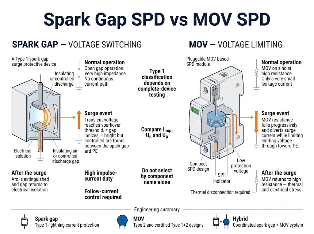
Cos'è un SPD basato su spinterometro?
Uno spinterometro utilizza elettrodi separati da uno spazio isolante controllato. In condizioni di tensione normale, il percorso rimane aperto.
Quando viene raggiunta la condizione di innesco dinamico, lo spinterometro si ionizza e forma un arco che devia la corrente di sovratensione. Dopo la sovratensione, l'SPD deve ritornare al suo stato non conduttivo.
Gli spinterometri a frequenza industriale possono utilizzare configurazioni ad aria, gas, carbonio, grafite, incapsulate, innescate o a spinterometri multipli. Tali design non devono essere considerati tecnicamente identici.
- È possibile ottenere un'elevata capacità di sopportazione delle correnti di fulmine.
- È possibile l'isolamento elettrico durante il normale funzionamento.
- Il comportamento della corrente susseguente rappresenta un fattore chiave per la disponibilità del sistema.
- È necessario verificare il comportamento dinamico di innesco e della tensione residua.
Cos'è un SPD basato su MOV?
Un MOV è un varistore a ossido metallico caratterizzato da una relazione tensione-corrente fortemente non lineare.
All'aumentare della tensione, la sua resistenza diminuisce. Il MOV devia quindi la corrente di sovratensione e limita la tensione sul circuito protetto.
I MOV consentono la realizzazione di prodotti compatti per guida DIN, cartucce estraibili, indicatori di stato e contatti remoti. L'SPD completo deve comunque gestire le condizioni di TOV, calore e guasto da cortocircuito.
- È possibile ottenere prestazioni di limitazione della bassa tensione.
- I design compatti e collegabili sono comuni.
- La selezione di Uc e il comportamento TOV sono fondamentali.
- La disconnessione termica è parte integrante del design di sicurezza.[7]
Un SPD di Tipo 1 deve necessariamente utilizzare uno spinterometro?
N. Gli spinterometri sono comuni negli scaricatori di corrente da fulmine di Tipo 1, ma il Tipo 1 è una classificazione di prova per l'SPD completo o per la modalità di protezione dichiarata.
Un dispositivo di Tipo 1 è associato al carico di corrente impulsiva da fulmine utilizzando la forma d'onda 10/350 μs e il valore Iimp dichiarato. Uno spinterometro non dimostra di per sé la conformità al Tipo 1. Un dispositivo basato su MOV testato non è automaticamente escluso dalla classificazione di Tipo 1 o Tipo 1+2.[3][4]
Perché gli spinterometri vengono spesso scelti per applicazioni di Tipo 1
Il vantaggio deriva dal prodotto completo progettato, non dalla dicitura “spinterometro” su una pagina di catalogo.
Scarica di corrente da fulmine
Gli SPD di Tipo 1 possono essere installati laddove sia necessario gestire correnti di fulmine parziali. Le strutture a spinterometro sono ampiamente progettate per questo impiego ad alta energia.
Separazione elettrica
Uno spinterometro aperto può offrire un'impedenza molto elevata durante il normale funzionamento. Ciò è particolarmente rilevante per determinati percorsi N-PE e per le applicazioni sensibili alle correnti di dispersione.
Comportamento di modellazione dell'onda
Dopo l'innesco, uno spinterometro ben progettato può creare un percorso di scarica a bassa impedenza. La tensione di innesco dinamica, la tensione d'arco e il coordinamento del sistema rimangono fattori importanti.
Evitare una falsa gerarchia: “spinterometro = premium” e “MOV = fascia bassa” non sono regole ingegneristiche valide. Phoenix Contact offre pubblicamente strutture di Tipo 1+2 basate su spinterometro, varistore e soluzioni coordinate spinterometro-più-varistore, dimostrando che architetture diverse possono soddisfare esigenze progettuali differenti.[4]
Perché gli spinterometri sono ampiamente utilizzati per la protezione N-PE nei sistemi 3+1
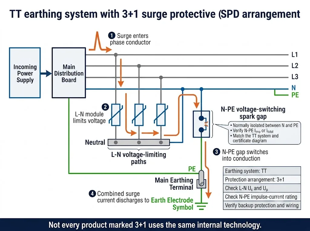
Per una configurazione TT 3+1, il percorso N-PE non è un elemento secondario. Può trasportare la corrente di scarica combinata proveniente dai percorsi di protezione fase-neutro.
In una tipica configurazione trifase 3+1, tre percorsi di protezione operano tra L1-N, L2-N e L3-N. Un percorso di protezione separato opera tra N e PE.
I moduli N-PE basati su spinterometro sono ampiamente utilizzati poiché rimangono elettricamente separati durante il normale funzionamento e forniscono un percorso di scarica ad alta corrente definito durante una sovratensione.
DEHN specifica scaricatori N-PE di Tipo 1 basati su spinterometro per circuiti 3+1 e 1+1 tra neutro e terra di protezione, inclusi i prodotti destinati ai sistemi TT.[5][6]
Importante: “3+1” descrive una configurazione circuitale. Non garantisce che ogni fornitore utilizzi la stessa tecnologia dei componenti interni, la stessa distribuzione Iimp o lo stesso schema elettrico di certificazione.
Verificare separatamente il percorso N-PE
- Configurazione di messa a terra del sistema
- N-PE Uc
- N-PE Up
- Iimp o Itotal N-PE
- Schema elettrico 1+1 o 3+1
- Marcatura della modalità di protezione
- Protezione di emergenza
- Modello esatto del certificato
La corrente susseguente è uno dei parametri di verifica più importanti nell'acquisto di uno spinterometro
Collega la struttura interna dell'SPD alle effettive condizioni di cortocircuito e al dispositivo di protezione a monte nel punto di installazione.
Lo spinterometro si innesca
Il picco di sovratensione innalza la tensione al di sopra del livello di scarica dinamica. Lo spinterometro si ionizza e crea un percorso ad arco.
Il picco di sovratensione termina.
Il sistema elettrico può continuare ad alimentare corrente attraverso la bassa tensione d'arco. Questa è la corrente di seguito.
L'SPD deve ripristinarsi.
Il design deve limitare, estinguere o prevenire tale corrente senza causare scatti intempestivi o danni a monte inaccettabili.
Cosa dovrebbe richiedere l'acquirente
- Dati sulle prestazioni della corrente susseguente Ifi o equivalenti
- Corrente di cortocircuito presunta nel punto di installazione
- Fusibile o interruttore automatico a monte consentito
- Requisiti di protezione di riserva e selettività
- Corrente nominale di cortocircuito dell'intero dispositivo di protezione da sovratensioni (SPD)
Non generalizzare tutti gli spinterometri
I design tradizionali e moderni possono comportarsi in modo differente. Phoenix Contact documenta prodotti a spinterometro progettati per funzionare senza corrente susseguente di rete, mentre la Guida all'installazione elettrica di Schneider definisce la Ifi come una caratteristica legata allo spinterometro che deve essere valutata in relazione alla corrente di cortocircuito presunta.[3][8]
Perché il solo "tempo di risposta" non è sufficiente per selezionare un SPD di Tipo 1
Un valore espresso in nanosecondi a livello di componente non descrive lo stress di tensione installato a cui sono soggette le apparecchiature a valle.
L'effettiva capacità protettiva dipende anche da
- Tensione di innesco dinamica
- Caratteristica tensione-corrente del MOV
- Ampiezza e forma d'onda dell'impulso
- Up dichiarato e misurato
- Induttanza interna ed esterna
- Lunghezza del conduttore di collegamento
- Modi di protezione e coordinamento a valle
Regola di approvvigionamento: Non approvare un SPD di Tipo 1 basandosi esclusivamente sulla dichiarazione di un fornitore riguardo a un tempo di risposta più rapido. Confrontare le prestazioni certificate, il comportamento tensione-tempo, le condizioni di installazione e i requisiti di protezione di riserva dell'intero dispositivo.
La corrente di dispersione, la TOV e l'invecchiamento richiedono verifiche differenti
Progetti basati su MOV
Verificare il margine Uc, la resistenza TOV, la stabilità termica, il comportamento della corrente di dispersione, la disconnessione termica e l'indicazione di fine vita. Una sovratensione anomala prolungata può surriscaldare un MOV se il progetto di protezione è inadeguato.[7]
Design a spinterometro
Verificare l'innesco dinamico, il contenimento dell'arco, le prestazioni della corrente di seguito, la resistenza all'impulso e il recupero dopo la scarica. Non dare per scontata una durata operativa illimitata.
Progetti ibridi
Verificare che il coordinamento faccia parte del prodotto testato o del sistema approvato dal produttore. Non creare ibridi non verificati combinando moduli arbitrari.
Quale struttura dovrebbe valutare un acquirente B2B?
La tabella costituisce un punto di partenza per la revisione delle specifiche, non una prescrizione universale di prodotto.
La commutazione della corrente di fulmine o l'isolamento N-PE sono fondamentali per il progetto
Concentrarsi sulle prestazioni dell'intero dispositivo anziché presumere che ogni spinterometro fornisca lo stesso risultato.
- L'installazione si trova al confine di una zona di protezione contro i fulmini di Tipo 1.
- È necessario verificare un percorso di scarica N-PE di tipo TT 1+1 o 3+1.
- La separazione elettrica nello stato normale è importante.
- Seguire la corrente; è possibile verificare la protezione Ifi e a monte.
La limitazione di tensione compatta di Tipo 1+2 e la manutenzione innestabile sono prioritarie
Il modello completo deve comunque superare i test di Tipo 1 e Tipo 2 richiesti.
- La larghezza del pannello e i moduli sostituibili sono fattori rilevanti.
- È necessario un valore Up dichiarato basso per una protezione coordinata.
- I dati relativi a Uc, TOV e disconnessione termica sono disponibili.
- Il certificato e le correnti di cortocircuito nominali sono conformi al progetto.
Il progetto richiede la gestione di correnti di fulmine e una tensione residua inferiore in un unico sistema
Ibrido non significa che moduli arbitrari possano essere assemblati insieme.
- La combinazione è testata o approvata dal produttore.
- Le modalità di protezione e il coordinamento interno sono documentati.
- La tecnologia N-PE è identificata separatamente.
- Le regole di installazione e di protezione di backup sono chiare.
| Applicazione | Struttura da valutare | Verifiche ingegneristiche primarie |
|---|---|---|
| Costruzione con LPS esterno | Tipo 1 o Tipo 1+2 certificato, spinterometro, MOV o ibrido approvato | Iimp, Up, posizione LPZ, modalità di protezione e ambito della certificazione richiesti |
| Quadro elettrico industriale principale | Tipo 1 per servizio gravoso o Tipo 1+2 coordinato | Iimp, Isccr, corrente susseguente, coordinamento dei fusibili e disponibilità |
| Quadro principale per sistema TT | Configurazione 1+1 o 3+1 con modulo N-PE verificato | Iimp/Itotal, Uc, Up, schema di sistema e certificato N-PE |
| Pannello OEM compatto | Combinato compatto di Tipo 1+2 | Larghezza, calore, terminali, formato di sostituzione e documentazione |
| Posizione di elevata corrente di guasto | SPD con prestazioni documentate di cortocircuito e protezione di riserva | Corrente di guasto presunta, Isccr, Ifi ove pertinente e dispositivo a monte |
| Apparecchiature sensibili a valle | SPD coordinato di Tipo 1/Tipo 2 o combinato verificato | Up, lunghezza del collegamento, comportamento della tensione residua e coordinamento dell'isolamento |
| Gamma di prodotti a magazzino dell'importatore o del distributore | Modelli standard limitati e chiaramente differenziati | Sistemi di rete regionali, opzioni Uc, certificati, accessori e moduli di ricambio |
Flusso di lavoro per la verifica degli SPD di Tipo 1
Passare dalla definizione del sistema alla corrispondenza dei documenti e all'approvazione dei campioni. Non iniziare con il colore dell'alloggiamento, il logo o un numero kA di intestazione.
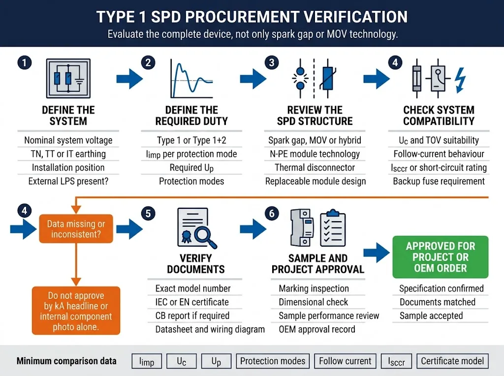
1. Dati di sistema
- Tensione nominale e massima del sistema
- Configurazione TN-C, TN-S, TT o IT
- Monofase o trifase
- LPS esterno e posizione di installazione
- Corrente di cortocircuito presunta
- Dispositivo di protezione a monte
2. Specifica SPD
- Tipo 1 o Tipo 1+2
- Iimp per modalità di protezione
- Uc e Up
- Iimp o Itotal N-PE
- Prestazioni della corrente susseguente
- Protezione di riserva e Isccr
3. Documenti di verifica
- Numero di modello esatto
- Certificato IEC o EN
- Rapporto CB ove richiesto
- Scheda tecnica e schema elettrico
- Esempio di marcatura ed etichettatura del prodotto
- Verbale di approvazione del campione
Fase di approvazione: La scheda tecnica, il certificato, il rapporto di prova, la marcatura del prodotto, lo schema elettrico e il campione fisico devono identificare la medesima configurazione di prodotto. Qualsiasi discrepanza deve essere chiarita prima dell'approvazione del progetto o della produzione in serie.
Come LEEYEE trasforma questa guida in una decisione B2B verificabile
Il contenuto tecnico deve essere correlato ai dati reali del prodotto, alla capacità di collaudo e all'ambito di certificazione. I controlli interni supportano la revisione tecnica, ma non sostituiscono la certificazione indipendente.
Controlli di ingegneria e produzione disponibili
LEEYEE documenta pubblicamente le seguenti capacità di test e ispezione per lo sviluppo di SPD, la verifica della produzione e la revisione da parte dell'acquirente.[9]
Utilizzato per esaminare il comportamento elettrico dei componenti prima che vengano accettati nel processo di produzione dell'SPD finito.
Utilizzato per valutare le prestazioni della corrente impulsiva dichiarata in base alla forma d'onda e alla disposizione di prova applicabili.
Utilizzato per osservare il comportamento in condizioni di tensione anomala prolungata e stress termico.
Utilizzato per esaminare la risposta dell'SPD in un ambiente di prova combinato con sovratensioni di tensione e corrente.
SPD Tipo 1+2 LEEYEE LY1-12.5/1(S)+1
Questo esempio illustra perché gli acquirenti debbano distinguere una struttura a spinterometro di potenza da un prodotto ibrido MOV + GDT.
Errori comuni in fase di acquisto
Il Tipo 1 indica uno spinterometro
Il Tipo 1 viene verificato tramite la classificazione di prova del dispositivo completo e l'Iimp dichiarato, non dall'etichetta del componente.
Un MOV di Tipo 1 è intrinsecamente inferiore
Un dispositivo di Tipo 1+2 basato su MOV testato potrebbe essere adatto all'applicazione. Confronta le specifiche complete e i requisiti di sistema.
Imax viene trattato come Iimp
Imax è solitamente associato a una forma d'onda 8/20 μs. Iimp è il parametro della corrente impulsiva di fulminazione di Tipo 1.
Il tempo di risposta è determinante
Up, forma d'onda, induttanza del cablaggio, scarica e coordinamento del sistema sono più significativi di una dichiarazione di un nanosecondo.
Il percorso N-PE viene ignorato
Nei sistemi TT 3+1, il percorso N-PE può presentare una tecnologia e una corrente nominale totale differenti rispetto ai moduli L-N.
La corrente susseguente non viene verificata
Un SPD a spinterometro deve essere idoneo alle condizioni di cortocircuito previste e al dispositivo di protezione a monte.
Una foto del prodotto attesta la conformità
Solo dati di modello, certificati, rapporti, marcature e campioni corrispondenti supportano l'approvazione.
Uc viene selezionato esclusivamente in base alla tensione nominale
Uc deve inoltre essere idoneo al sistema di messa a terra, alla tolleranza di tensione e alle condizioni TOV.
Hai bisogno di assistenza per confermare le specifiche di un SPD di Tipo 1?
Inviare la tensione di sistema, la disposizione della messa a terra, il valore Iimp richiesto e i requisiti di certificazione. LEEYEE può fornire assistenza nel confronto della struttura di protezione, dei valori nominali e dell'esatta gamma di modelli prima dell'approvazione del campione o della quotazione OEM.
Domande frequenti sugli SPD a spinterometro rispetto agli SPD a varistore (MOV)
Uno spinterometro è preferibile a un MOV per un SPD di Tipo 1?
Non in ogni applicazione. Gli spinterometri sono ampiamente utilizzati per elevate correnti di fulmine e per compiti tra N e PE. I MOV forniscono un comportamento di limitazione della tensione e possono essere utilizzati in prodotti di Tipo 1+2 testati. Selezionare l'SPD completo in base al sistema, ai valori nominali e alla documentazione.
Un SPD basato su MOV può soddisfare i requisiti di Tipo 1?
Sì. Il produttore deve dimostrare che l'SPD completo o la modalità di protezione dichiarata soddisfino i requisiti di prova e i valori nominali applicabili per il Tipo 1. Phoenix Contact elenca pubblicamente prodotti di Tipo 1+2 basati su varistori, il che conferma che il Tipo 1+2 non è limitato all'architettura a spinterometro.[4]
Perché viene spesso utilizzato uno spinterometro tra N e PE?
È in grado di fornire separazione elettrica durante il normale funzionamento e un percorso di scarica ad alta corrente in caso di sovratensione. Gli scaricatori N-PE basati su spinterometro sono ampiamente utilizzati nei circuiti 1+1 e 3+1, in particolare per le applicazioni TT.[5]
Ogni spinterometro produce una corrente susseguente di linea?
No. Il comportamento della corrente susseguente dipende dal design. Alcuni prodotti specificano una capacità di estinzione, mentre i moderni design innescati possono essere progettati per funzionare senza corrente susseguente di rete. Verificare i dati specifici del modello.
Uno scaricatore di sovratensioni (SPD) a spinterometro ha un livello di protezione di tensione pari a zero?
No. Lo stress di tensione installato include l'innesco dinamico, la tensione d'arco, l'induttanza interna e gli effetti di connessione. Utilizzare il valore Up dichiarato e testato del dispositivo completo.
Il Tipo 1+2 contiene sempre sia uno spinterometro che un MOV?
No. Il Tipo 1+2 indica che il dispositivo completo soddisfa i requisiti dichiarati per il Tipo 1 e il Tipo 2. L'architettura interna può essere basata su spinterometro, su MOV o su una combinazione coordinata.
Cosa dovrebbe verificare per primo un acquirente OEM?
Iniziare con la tensione di sistema, il sistema di messa a terra, le modalità di protezione, la posizione di installazione, i valori richiesti di Iimp, Uc, Up, le condizioni di cortocircuito e i requisiti di certificazione. Discutere di branding e imballaggio solo dopo aver confermato la configurazione tecnica.
È opportuno utilizzare un valore nominale di 100 kA per confrontare gli SPD di Tipo 1?
No. Determinare se il valore si riferisce a Iimp, Itotal, In o Imax; identificare la forma d'onda e la modalità di protezione; verificare inoltre se il dato si applica per polo, per percorso o all'intero assemblaggio.
Riferimenti
Le dichiarazioni tecniche sono state revisionate in conformità con le attuali pagine IEC, le risorse ingegneristiche dei principali produttori e le informazioni di test e di prodotto di prima parte LEEYEE chiaramente identificate.
Revisionato dal team tecnico LEEYEE. Ultimo aggiornamento: 23 luglio 2026.
- Rimossi l'H1 interno e l'hero della landing page poiché il titolo della pagina è fornito dal template WordPress.
- Spostati la risposta rapida, l'indice e le informazioni di aggiornamento in un'apertura dell'articolo compatta.
- Inserite tutte e tre le infografiche ingegneristiche all'interno delle relative sezioni tecniche.
- Ridotti gli elementi promozionali a una singola CTA di specifica B2B leggera.
- Convertite le tabelle desktop in schede leggibili da mobile senza scorrimento orizzontale.
- IEC 61643-11:2025 — Dispositivi di protezione contro le sovratensioni a bassa tensione collegati ai sistemi di alimentazione a bassa tensione in corrente alternata: requisiti e metodi di prova.
- IEC 61643-01:2024 — Dispositivi di protezione contro le sovratensioni a bassa tensione: requisiti generali e metodi di prova.
- Guida all'installazione elettrica di Schneider Electric: il dispositivo di protezione contro le sovratensioni (SPD), incluse le spiegazioni di Iimp, Up e Ifi.
- Phoenix Contact: protezione contro le sovratensioni di tipo 1+2, incluse le strutture di prodotto basate su spinterometro, varistore e ibride coordinate.
- DEHN: scaricatori di corrente da fulmine N-PE per circuiti 1+1 e 3+1.
- DEHN: scaricatore di corrente totale basato su spinterometro DEHNgap per configurazioni 1+1 e 3+1 in sistemi TT.
- Littelfuse — Informazioni sui MOV con protezione termica riguardanti la protezione da sovratensioni anomale prolungate e surriscaldamento.
- Phoenix Contact — Tecnologia a spinterometro, comportamento della tensione residua e design privi di corrente di seguito.
- LEEYEE — Attrezzature documentate per la produzione e la verifica di SPD, inclusi test su MOV/GDT, impulsi di fulmine, stabilità termica e test con onde combinate.
- LEEYEE LY1-12.5/1(S)+1 — Dati di prodotto di Tipo 1+2, L-N/N-PE con elementi di protezione MOV + GDT dichiarati e valori nominali di corrente impulsiva.
- Certificati LEEYEE: guida alla verifica dei modelli e all'ambito di certificazione per i tipi 1+2 selezionati LY1-12.5 e LY1-7.
Gli standard e i portafogli prodotti sono soggetti a variazioni. Prima dell'approvazione, verificare l'edizione, lo stato del certificato, l'adozione nazionale e il modello esatto del produttore richiesto dal progetto.
