
È necessario collegare il contatto di allarme remoto di un SPD a un ingresso digitale PLC? Questa guida mostra come collegare contatti puliti NO / NC / COM a ingressi digitali PLC, spie di allarme, BMS, SCADA o sistemi di monitoraggio per quadri di controllo, quadri di distribuzione e armadi OEM.
Risposta rapida: Il contatto di allarme remoto di un SPD è solitamente un contatto ausiliario pulito contrassegnato come NO, NC e COM. Non emette di per sé 24 VDC, 110 VAC o 220 VAC. Il PLC, il circuito di allarme o il sistema di monitoraggio deve fornire la tensione di rilevamento.
Per il monitoraggio tramite PLC, il contatto SPD agisce come un interruttore all'interno del circuito di ingresso digitale del PLC. Utilizzare NC-COM per il monitoraggio fail-safe, oppure NO-COM per un semplice segnale di allarme in caso di guasto.
Questo articolo è scritto per costruttori di quadri, produttori di armadi PLC, team di manutenzione industriale, fornitori di scatole di giunzione FV, acquirenti OEM ed elettricisti che necessitano di istruzioni pratiche per il cablaggio degli allarmi remoti.
Se ti serve solo il significato base degli indicatori visivi e dello stato remoto, consulta la nostra guida correlata: Meccanismo di funzionamento dell'SPD e indicazione dello stato . Questa pagina si concentra sul cablaggio.
Indice dei contenuti
Cos'è il contatto di allarme remoto SPD?
Il contatto di allarme remoto è un piccolo terminale ausiliario presente su alcuni dispositivi di protezione contro le sovratensioni. Cambia stato quando il modulo SPD raggiunge la fine della vita utile, interviene internamente o segnala uno stato di guasto.
Nella maggior parte delle applicazioni a pannello, il contatto remoto viene utilizzato per inviare un semplice segnale di stato a un PLC, BMS, SCADA, relè di allarme, lampada spia o sistema di monitoraggio della manutenzione.
| Terminale | Significato | Stato normale tipico | Stato di guasto tipico | Uso comune |
|---|---|---|---|---|
| COM | Terminale comune | Punto di contatto condiviso | Punto di contatto condiviso | Lato comune del loop di monitoraggio |
| NC | Normalmente chiuso | Chiuso con COM | Aperto da COM | Monitoraggio fail-safe o rilevamento rottura cavo |
| NO | Normalmente aperto | Aperto da COM | Chiuso con COM | Trigger di allarme semplice o circuito spia |
Importante: il segnale remoto non è un'uscita di potenza
Non trattare il terminale di allarme remoto SPD come un alimentatore. Il terminale funziona solitamente come un contatto di commutazione. Apre o chiude solo un circuito.
- Non fornisce alimentazione a un ingresso PLC.
- Non genera direttamente un segnale di allarme a 24 V.
- Non deve essere utilizzato per pilotare una lampada, un cicalino o una bobina di relè oltre la sua capacità di contatto nominale.
- Controllare sempre la tensione e la corrente nominali del contatto remoto nella scheda tecnica dell'SPD.
Cablaggio di base: contatto remoto SPD verso ingresso digitale PLC
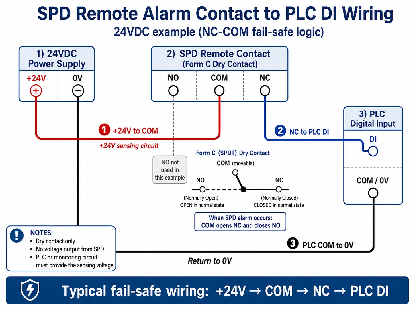
Il metodo di cablaggio più comune consiste nel collegare il contatto pulito SPD a un circuito di ingresso digitale del PLC. L'esempio seguente mostra un circuito di ingresso a 24 VDC che utilizza una logica fail-safe NC-COM.
In questo metodo, il percorso di cablaggio tipico è:
Cablaggio fail-safe +24V → COM → NC → PLC DI, con PLC COM / 0V che ritorna al terminale 0V dell'alimentatore di controllo.
| Punto di connessione | Cablaggio tipico | Significato PLC |
|---|---|---|
| Alimentazione all'SPD | +24V → COM | Il circuito di ingresso del PLC fornisce la tensione di rilevamento. |
| Da SPD a ingresso digitale PLC | NC → DI PLC | Il PLC legge lo stato del contatto SPD tramite il punto DI. |
| Ritorno comune PLC | PLC COM / 0V → 0V | Il circuito di monitoraggio ha un percorso di ritorno completo. |
| Condizione normale | NC-COM chiuso | DI ON = SPD normale. |
| Condizione di allarme | NC-COM aperto | DI OFF = guasto SPD o interruzione del filo di monitoraggio. |
Passaggi di base per il cablaggio NC-COM PLC
- Collegare l'alimentazione di controllo +24V al contatto remoto dell'SPD COM terminale.
- Collegare il contatto remoto dell'SPD NC terminale all'ingresso digitale del PLC DI.
- Collegare PLC COM / 0V al terminale 0V dell'alimentazione di controllo.
- Programmare o etichettare DI ON come stato normale SPD.
- Programmare o etichettare DI OFF come allarme SPD, segnale di fine vita o interruzione del filo di monitoraggio.
Nello stato normale, NC-COM rimane chiuso, quindi l'ingresso del PLC riceve il segnale previsto. Quando l'SPD raggiunge lo stato di guasto, il COM si apre da NC e si chiude verso NO. Lo stato dell'ingresso del PLC cambia e il sistema di monitoraggio può attivare un allarme.
Stato normale SPD
NC-COM chiuso → PLC DI ON → Il sistema legge come normale.
Guasto SPD o interruzione filo
NC-COM aperto → PLC DI OFF → Allarme o avviso di manutenzione.
Nota pratica: Il cablaggio dell'ingresso PLC dipende dal tipo di ingresso, dalla tensione di controllo e dallo standard di cablaggio del quadro. Lo schema mostra la logica di monitoraggio. Il cablaggio finale deve seguire il manuale del PLC e la portata dei contatti dell'SPD.
NO o NC: quale contatto utilizzare?
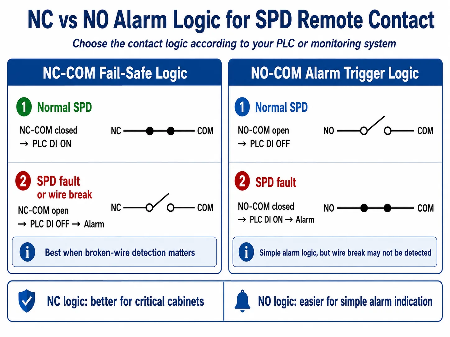
Entrambi i contatti NO e NC possono essere corretti. La scelta giusta dipende da come il PLC, il BMS, il SCADA o il circuito di allarme definiscono un guasto.
NC-COM per monitoraggio fail-safe
Nel funzionamento normale, NC-COM è chiuso, quindi l'ingresso del PLC è attivo. Se l'SPD si guasta o il filo si rompe, il circuito si apre e il PLC può attivare un allarme.
Questa soluzione è solitamente migliore per quadri critici perché può rilevare anche un'interruzione del filo di monitoraggio.
NO-COM per attivazione allarme semplice
Nel funzionamento normale, NO-COM è aperto, quindi l'ingresso del PLC è inattivo. Quando l'SPD si guasta, NO-COM si chiude e l'ingresso del PLC si attiva.
Questa logica è semplice e facile da comprendere, ma un filo interrotto potrebbe non essere rilevato.
Come collegare il contatto di allarme remoto di un SPD a una spia o a un cicalino
Una spia di allarme o un cicalino devono avere la propria alimentazione. Il contatto remoto SPD deve solo commutare il circuito di allarme.
Per un semplice circuito di spia di allarme a 24VDC, la logica di cablaggio è solitamente:
- Collegare +24VDC a un lato della spia di allarme o del cicalino.
- Collegare l'altro lato della spia o del cicalino tramite il contatto NO-COM o NC-COM dell'SPD.
- Riportare il circuito a 0V.
- Confermare che la corrente di carico dell'allarme sia inferiore alla portata del contatto SPD.
Utilizzare un relè intermedio per carichi più elevati
Se la spia, il cicalino, la sirena o il dispositivo di allarme utilizzano una corrente più elevata o una tensione superiore, non commutarli direttamente tramite il contatto SPD. Utilizzare il contatto SPD per eccitare un relè intermedio o un modulo di interfaccia e lasciare che il relè commuti il carico.
Come monitorare più SPD con un unico PLC o sistema di monitoraggio
Molti quadri di controllo, quadri di stringa FV e sistemi di distribuzione utilizzano più di un SPD. Prima del cablaggio, decidere se il sistema di monitoraggio debba mostrare un allarme comune o identificare separatamente ciascun SPD.
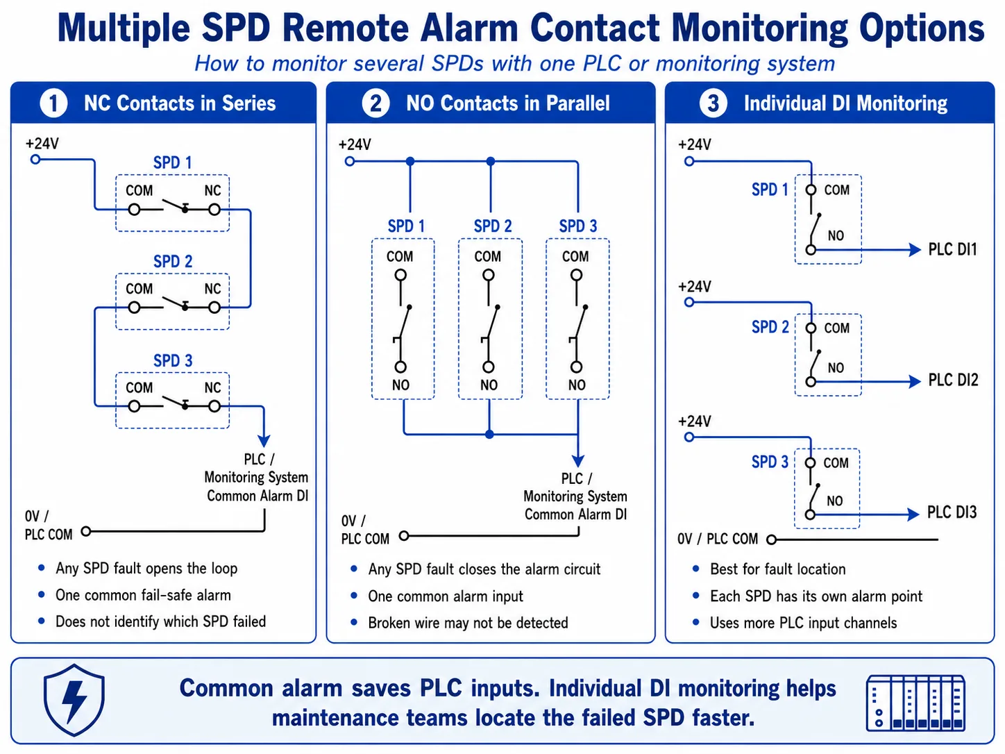
| Metodo di monitoraggio | Come funziona | Ideale per | Limitazione |
|---|---|---|---|
| Contatti NC in serie | Tutti i contatti NC-COM sono cablati in un unico loop in serie. Qualsiasi guasto dell'SPD apre il loop. | Allarme comune fail-safe per quadri importanti | Non identifica quale SPD ha subito un guasto |
| Contatti NO in parallelo | Tutti i contatti NO-COM sono cablati in parallelo. Qualsiasi guasto dell'SPD chiude il circuito di allarme. | Semplice spia di allarme comune o ingresso PLC | Un filo interrotto potrebbe non essere rilevato |
| Ingresso digitale (DI) individuale | Ogni contatto remoto SPD è cablato a un ingresso PLC separato. | SCADA, BMS, quadri di stringa FV e grandi quadri di controllo | Utilizza più ingressi PLC e più cablaggi |
Procedura di cablaggio passo-passo per un quadro PLC
Confermare il tipo di contatto SPD
Verificare se l'SPD dispone di terminali NO / NC / COM, solo NC-COM o un modulo di segnalazione remota opzionale. Non dare per scontato che ogni modello di SPD abbia la stessa disposizione dei terminali.
Controllare la portata dei contatti
Confermare la tensione e la corrente massime del contatto di allarme remoto. Il circuito di controllo deve rimanere entro questa portata nominale.
La portata dei contatti dipende dal modello di SPD. Prima del cablaggio, confermare la tensione nominale, la corrente nominale, il carico di commutazione minimo, la marcatura dei terminali e la sezione del conduttore consentita nella scheda tecnica.
Scegliere la logica NO o NC
Utilizzare NC-COM per un monitoraggio fail-safe, specialmente quando è importante il rilevamento di interruzione del filo. Utilizzare NO-COM per una semplice logica di allarme su guasto.
Corrispondere al tipo di ingresso digitale PLC
Seguire lo schema di cablaggio dell'ingresso PLC. Alcuni sistemi utilizzano ingressi sourcing, altri ingressi sinking. Il contatto SPD è solo un interruttore all'interno di quel circuito di ingresso.
Etichettare il terminale e la logica di allarme
Contrassegnare chiaramente il cablaggio del quadro: allarme SPD1, allarme SPD2, allarme SPD comune o allarme SPD del quadro di stringa FV. Etichette chiare riducono i tempi di manutenzione dopo il primo allarme di guasto.
Test prima della messa in servizio
Simulare lo stato del contatto o utilizzare il metodo di test dell'SPD consentito dal produttore. Confermare che il PLC, la spia di allarme, l'HMI, il BMS o il sistema SCADA mostrino lo stato corretto.
Errori di cablaggio comuni da evitare
| Errore | Perché è un problema | Pratica migliore |
|---|---|---|
| Supponendo che il terminale SPD emetta 24VDC | Il contatto remoto è solitamente un contatto pulito, non una fonte di alimentazione. | Fornire tensione dal circuito di ingresso PLC o da un'alimentazione di controllo esterna. |
| Pilotare un cicalino direttamente senza controllare la corrente | Il carico potrebbe superare la portata del contatto e danneggiare il contatto remoto. | Utilizzare un relè intermedio per carichi più elevati. |
| Utilizzo della logica NO per allarmi critici senza supervisione | Un filo interrotto potrebbe apparire identico a un normale stato di funzionamento. | Utilizzare il monitoraggio fail-safe NC quando la supervisione del cablaggio è importante. |
| Inserire tutti gli SPD su un unico allarme senza etichette | Il team di manutenzione sa che c'è un guasto, ma non dove si trova. | Utilizzare ingressi DI individuali per quadri importanti o etichettare chiaramente ogni SPD. |
| Ignorare le differenze tra i modelli di SPD CA/CC | Diversi modelli di SPD possono avere design o portate dei terminali remoti differenti. | Controllare la scheda tecnica prima del cablaggio finale del quadro. |
È opportuno specificare un SPD con segnale remoto per pannelli OEM?
Per molti quadri elettrici OEM, vale la pena specificare il segnale remoto quando il quadro è installato in un luogo difficile da ispezionare manualmente, o quando l'utente finale desidera un'uscita di allarme verso un sistema PLC, BMS o SCADA.
È particolarmente utile per:
- Quadri di controllo industriali con monitoraggio PLC
- Quadri di stringa FV e quadri di protezione lato inverter
- Quadri di distribuzione principali e quadri di sotto-distribuzione
- Quadri di alimentazione per telecomunicazioni e comunicazioni
- Locali tecnici non presidiati o siti remoti
- Pannelli OEM che richiedono terminali di allarme per la manutenzione
Per quadri semplici ed economici in cui è sufficiente un'ispezione visiva, può essere accettabile un SPD standard senza segnale remoto. La scelta dipende dai requisiti del progetto, dal metodo di manutenzione e dal sistema di monitoraggio del cliente.
I modelli di SPD LEEYEE possono supportare i requisiti di contatto di allarme remoto
Per quadri OEM e sistemi di distribuzione monitorati, gli SPD LEEYEE per guida DIN AC e gli SPD DC / PV selezionati possono essere forniti con terminali di segnalazione remota in base ai requisiti del progetto.
Prima di ordinare, verificare se il progetto necessita di terminali NO / NC / COM, la portata dei contatti richiesta, la logica di allarme, la marcatura dei terminali e lo schema di cablaggio del quadro.
Prima di ordinare SPD con contatto di allarme remoto, confermare questi dettagli
- SPD AC o SPD DC / PV
- Tensione di sistema e Uc o Ucpv richiesti
- Tipo SPD: Tipo 1, Tipo 2, o Tipo 1+2
- Configurazione dei poli: 1P, 2P, 3P, 4P, o 3P+N
- Contatto remoto richiesto: sì o no
- Terminali di contatto necessari: NO / NC / COM o solo NC-COM
- Tensione di ingresso PLC: 24VDC, 110VAC, 220VAC o altra
- Logica di allarme: NC fail-safe o NO a scatto di allarme
- Numero di SPD in un unico quadro
- Allarme comune o allarme individuale per ogni SPD
- Requisiti per etichetta OEM, marcatura terminali e schema di cablaggio
Hai bisogno di SPD con contatti di allarme remoto per il tuo quadro?
Inviaci la tensione del tuo sistema, il tipo di quadro, il tipo di SPD, la configurazione dei poli e la logica di allarme PLC. LEEYEE può aiutarti a consigliare un modello di SPD adatto con terminali di segnale remoto per quadri OEM, quadri di distribuzione, scatole di giunzione PV o quadri di controllo industriale.
FAQ: Cablaggio del contatto di allarme remoto SPD
Un allarme remoto SPD può collegarsi direttamente a un PLC?
Sì, in molte applicazioni può essere cablato a un ingresso digitale PLC come contatto pulito. Il circuito di ingresso del PLC deve fornire la tensione di rilevamento e il cablaggio deve corrispondere al tipo di ingresso del PLC.
L'uscita del terminale di segnale remoto SPD è 24VDC?
Di solito no. Il terminale di allarme remoto dell'SPD è normalmente un contatto pulito. Cambia tra stato aperto e chiuso, ma non genera autonomamente un segnale a 24VDC.
Dovrei utilizzare NO o NC per l'allerta di guasto SPD?
Utilizzare NO-COM se si desidera un semplice segnale di allarme quando l'SPD si guasta. Utilizzare NC-COM se si desidera un monitoraggio fail-safe, in cui un guasto dell'SPD o un filo interrotto possono entrambi attivare un allarme.
Può un ingresso PLC monitorare diversi SPD?
Sì. È possibile cablare i contatti NC in serie per un allarme comune fail-safe, o cablare i contatti NO in parallelo per un ingresso a scatto di allarme. Se è necessario identificare l'esatto SPD guasto, utilizzare un ingresso digitale PLC per ogni SPD.
Il contatto remoto SPD può azionare direttamente una spia di allarme?
Solo se la tensione e la corrente del circuito della lampada rientrano nella portata del contatto. Per carichi superiori, utilizzare il contatto dell'SPD per pilotare un relè intermedio invece di commutare il carico direttamente.
Il contatto dell'allarme remoto SPD è lo stesso della comunicazione Modbus o RS485?
No. Un contatto di allarme remoto SPD standard è un segnale a contatto pulito. Fornisce solo lo stato aperto o chiuso. Modbus o RS485 richiedono un'interfaccia di comunicazione o un gateway.
Ogni SPD in un armadio OEM dovrebbe includere il segnale remoto?
Non sempre. Il segnale remoto è consigliato quando il quadro è difficile da ispezionare, quando i team di manutenzione necessitano dello stato remoto o quando il progetto richiede l'integrazione dell'allarme PLC, BMS o SCADA.
Gli SPD AC e DC possono utilizzare la stessa logica di cablaggio per l'allarme remoto?
La logica di cablaggio del contatto pulito è spesso simile, ma il modello di SPD, la portata del contatto e la marcatura dei terminali possono differire. Confermare sempre la scheda tecnica prima di cablare i terminali di allarme remoto degli SPD AC o DC.
