
¿Necesita cablear el contacto de alarma remota de un SPD a una entrada digital de PLC? Esta guía muestra cómo conectar contactos secos NO / NC / COM a entradas digitales de PLC, lámparas de alarma, sistemas BMS, SCADA o sistemas de supervisión para cuadros de control, cuadros de distribución y armarios OEM.
Respuesta rápida: El contacto de alarma remota de un SPD es normalmente un contacto auxiliar seco marcado como NO, NC y COM. Por sí mismo, no suministra 24 VCC, 110 VCA ni 220 VCA. El PLC, el circuito de alarma o el sistema de supervisión deben proporcionar la tensión de detección.
Para la supervisión mediante PLC, el contacto del SPD funciona como un interruptor dentro del circuito de entrada digital del PLC. Utilice NC-COM para una supervisión a prueba de fallos, o NO-COM para una señal simple de alarma por fallo.
Este artículo está dirigido a constructores de cuadros, fabricantes de armarios de PLC, equipos de mantenimiento industrial, proveedores de cajas combinadoras fotovoltaicas, compradores OEM y contratistas eléctricos que necesiten información práctica sobre el cableado de alarmas remotas.
Si solo necesita conocer el significado básico de los indicadores visuales y del estado remoto, consulte nuestra guía relacionada: Mecanismo de funcionamiento e indicación de estado del SPD . Esta página se centra en el aspecto del cableado.
Índice
¿Qué es el contacto de alarma remota del SPD?
El contacto de alarma remota es un pequeño terminal auxiliar presente en algunos dispositivos de protección contra sobretensiones (SPD). Cambia el estado del contacto cuando el módulo SPD llega al final de su vida útil, se dispara internamente o muestra un estado de fallo.
En la mayoría de las aplicaciones de cuadros eléctricos, el contacto remoto se utiliza para enviar una señal de estado simple a un PLC, sistema BMS, SCADA, relé de alarma, lámpara indicadora o sistema de monitorización de mantenimiento.
| Terminal | Significado | Estado normal típico | Estado de fallo típico | Uso común |
|---|---|---|---|---|
| COM | Terminal común | Punto de contacto compartido | Punto de contacto compartido | Lado común del bucle de supervisión |
| NC | Normalmente cerrado | Cerrado con COM | Se abre desde COM | Monitorización a prueba de fallos o detección de rotura de hilo |
| NO | Normalmente abierto | Abierto desde COM | Se cierra con COM | Disparador de alarma simple o circuito de lámpara indicadora |
Importante: La señal remota no es una salida de potencia
No trate el terminal de alarma remota del SPD como una fuente de alimentación. El terminal funciona normalmente como un contacto de conmutación. Solo abre o cierra un circuito.
- No suministra energía a una entrada de PLC.
- No genera directamente una señal de alarma de 24V.
- No debe utilizarse para accionar una lámpara, un zumbador o una bobina de relé por encima de su capacidad nominal de contacto.
- Compruebe siempre la tensión y la corriente nominales del contacto remoto en la hoja de datos del SPD.
Cableado básico: contacto remoto de SPD a entrada digital de PLC
El método de cableado más común es conectar el contacto seco del SPD en un circuito de entrada digital de PLC. El ejemplo siguiente muestra un circuito de entrada de 24VDC utilizando lógica a prueba de fallos NC-COM.
En este método, la ruta de cableado típica es:
Cableado a prueba de fallos +24V → COM → NC → PLC DI, con el COM / 0V del PLC retornando al terminal de 0V de la fuente de alimentación de control.
| Punto de conexión | Cableado típico | Significado en el PLC |
|---|---|---|
| Fuente de alimentación para el SPD | +24V → COM | El circuito de entrada del PLC proporciona la tensión de detección. |
| SPD a entrada digital de PLC | NC → PLC DI | El PLC lee el estado del contacto del SPD a través del punto DI. |
| Retorno común del PLC | PLC COM / 0V → 0V | El circuito de monitorización tiene una ruta de retorno completa. |
| Condición normal | NC-COM cerrado | DI ON = SPD normal. |
| Estado de alarma | NC-COM abierto | DI OFF = fallo del SPD o cable de monitorización roto. |
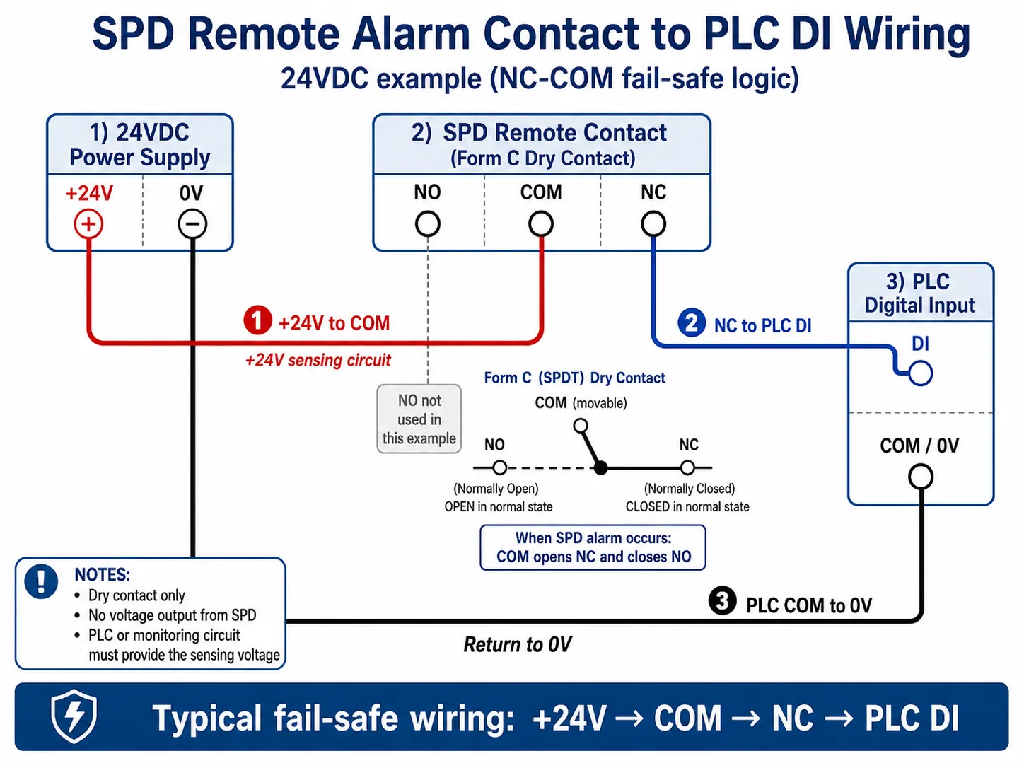
Pasos básicos para el cableado del PLC NC-COM
- Conecte la alimentación de control +24V al terminal del contacto remoto COM del SPD.
- Conecte el terminal del contacto remoto NC del SPD a la entrada digital del PLC DI.
- Conecte PLC COM / 0V de vuelta al terminal de 0V de la fuente de alimentación de control.
- Programe o etiquete DI ON como estado normal del SPD.
- Programe o etiquete DI OFF como alarma del SPD, señal de fin de vida útil o cable de monitorización roto.
En estado normal, NC-COM permanece cerrado, por lo que la entrada del PLC recibe la señal esperada. Cuando el SPD alcanza el estado de fallo, COM se abre desde NC y se cierra hacia NO. El estado de la entrada del PLC cambia, y el sistema de monitorización puede activar una alarma.
Estado normal del SPD
NC-COM cerrado → PLC DI ON → El sistema lee normal.
Fallo del SPD o rotura de cable
NC-COM abierto → PLC DI OFF → Alarma o aviso de mantenimiento.
Nota práctica: El cableado de entrada del PLC depende del tipo de entrada, la tensión de control y el estándar de cableado del armario. El diagrama muestra la lógica de monitorización. El cableado final debe seguir el manual del PLC y la capacidad nominal del contacto del SPD.
NO o NC: ¿Qué contacto debería utilizar?
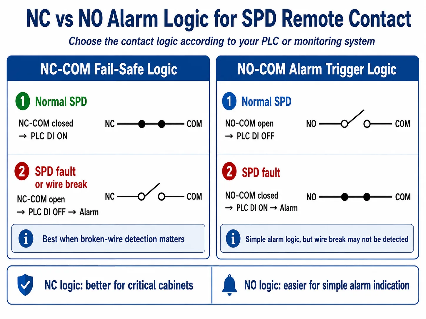
Tanto NO como NC pueden ser correctos. La elección correcta depende de cómo el PLC, BMS, SCADA o circuito de alarma defina un fallo.
NC-COM para monitorización de seguridad contra fallos (Fail-Safe)
En funcionamiento normal, NC-COM está cerrado, por lo que la entrada del PLC está activa. Si el SPD falla o el cable se rompe, el circuito se abre y el PLC puede activar una alarma.
Esto suele ser mejor para armarios críticos, ya que también puede detectar un cable de monitorización roto.
NO-COM para disparo de alarma simple
En funcionamiento normal, NO-COM está abierto, por lo que la entrada del PLC está inactiva. Cuando el SPD falla, NO-COM se cierra y la entrada del PLC se activa.
Esta lógica es sencilla y fácil de entender, pero es posible que no se detecte un cable roto.
Cómo cablear el contacto de alarma remota de un SPD a una lámpara o zumbador de alarma
Una lámpara de alarma o un zumbador deben tener su propia fuente de alimentación. El contacto remoto del SPD solo debe conmutar el circuito de alarma.
Para un circuito sencillo de lámpara de alarma de 24 V CC, la lógica de cableado suele ser:
- Conecte +24 V CC a un lado de la lámpara de alarma o del zumbador.
- Conecte el otro lado de la lámpara o del zumbador a través del contacto NO-COM o NC-COM del SPD.
- Retorne el circuito a 0 V.
- Confirme que la corriente de carga de la alarma sea inferior a la capacidad nominal de contacto del SPD.
Utilice un relé intermedio para cargas superiores
Si la lámpara, el zumbador, la sirena o el dispositivo de alarma utiliza una corriente o tensión mayor, no lo conmute directamente a través del contacto del SPD. Utilice el contacto del SPD para activar un relé intermedio o un módulo de interfaz y deje que el relé conmute la carga.
Cómo supervisar varios SPD con un solo PLC o sistema de supervisión
Muchos paneles de control, cajas combinadoras fotovoltaicas y sistemas de distribución utilizan más de un SPD. Antes de realizar el cableado, decida si el sistema de supervisión debe mostrar una alarma común o identificar cada SPD por separado.
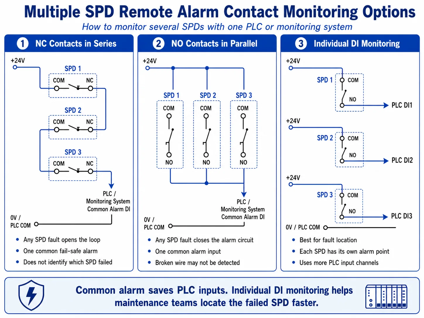
| Método de supervisión | Cómo Funciona | Mejor Para | Limitación |
|---|---|---|---|
| Contactos NC en serie | Todos los contactos NC-COM están cableados en un bucle en serie. Cualquier fallo en un SPD abre el bucle. | Alarma común a prueba de fallos para paneles importantes | No identifica qué SPD ha fallado |
| Contactos NO en paralelo | Todos los contactos NO-COM están cableados en paralelo. Cualquier fallo en un SPD cierra el circuito de alarma. | Lámpara de alarma común sencilla o entrada de PLC | Es posible que no se detecte un cable roto |
| Entrada DI individual | Cada contacto remoto del SPD está cableado a una entrada de PLC independiente. | SCADA, BMS, cajas combinadoras fotovoltaicas y paneles de control de gran tamaño | Utiliza más entradas de PLC y más cableado |
Procedimiento de cableado paso a paso para un armario de PLC
Confirme el tipo de contacto del SPD
Compruebe si el SPD tiene terminales NO/NC/COM, solo NC-COM, o un módulo de señal remota opcional. No asuma que todos los modelos de SPD tienen la misma disposición de terminales.
Compruebe la capacidad nominal del contacto
Confirme la tensión y la corriente máximas del contacto de alarma remota. El circuito de control debe mantenerse dentro de esta capacidad nominal.
La capacidad nominal del contacto depende del modelo de SPD. Antes de realizar el cableado, confirme la tensión nominal, la corriente nominal, la carga mínima de conmutación, el marcado de los terminales y el tamaño de conductor permitido en la hoja de datos.
Elija la lógica NA o NC
Utilice NC-COM para la monitorización a prueba de fallos (fail-safe), especialmente cuando la detección de rotura de cable sea importante. Utilice NO-COM para una lógica sencilla de alarma en caso de fallo.
Coincida con el tipo de entrada digital del PLC
Siga el diagrama de cableado de entrada del PLC. Algunos sistemas utilizan entradas de tipo "sourcing" (fuente) y otros de tipo "sinking" (sumidero). El contacto del SPD es solo un interruptor dentro de ese circuito de entrada.
Etiquete los terminales y la lógica de alarma
Marque claramente el cableado del armario: alarma SPD1, alarma SPD2, alarma común de SPD o alarma de SPD de caja combinadora fotovoltaica. Un etiquetado claro reduce el tiempo de mantenimiento después de la primera alarma de fallo.
Pruebe antes de la puesta en servicio
Simule el estado del contacto o utilice el método de prueba del SPD permitido por el fabricante. Confirme que el PLC, la lámpara de alarma, la HMI, el BMS o el sistema SCADA muestran el estado correcto.
Errores de cableado comunes que deben evitarse
| Error | Por qué es un problema | Mejor práctica |
|---|---|---|
| Suponiendo que el terminal del SPD emite 24 VCC | El contacto remoto suele ser un contacto seco, no una fuente de alimentación. | Suministre voltaje desde el circuito de entrada del PLC o desde una fuente de alimentación de control externa. |
| Activar un zumbador directamente sin verificar la corriente | La carga puede exceder la capacidad nominal del contacto y dañar el contacto remoto. | Utilice un relé intermedio para cargas más elevadas. |
| Usar lógica NA para alarmas críticas sin supervisión | Un cable roto puede parecer idéntico a un estado normal en funcionamiento. | Utilice la monitorización a prueba de fallos NC cuando la supervisión del cableado sea importante. |
| Conectar todos los SPD a una sola alarma sin etiquetas | El equipo de mantenimiento sabe que hay un fallo, pero no sabe dónde está. | Utilice entradas DI individuales para paneles importantes o etiquete cada SPD claramente. |
| Ignorar las diferencias entre modelos de SPD de CA/CC | Diferentes modelos de SPD pueden tener diseños o clasificaciones de terminales remotos distintos. | Consulte la hoja de datos antes del cableado final del armario. |
¿Debería especificar un SPD con señal remota para paneles OEM?
Para muchos cuadros eléctricos OEM, vale la pena especificar la señal remota cuando el cuadro se instala en un lugar difícil de inspeccionar manualmente, o cuando el usuario final desea una salida de alarma a un sistema PLC, BMS o SCADA.
Es especialmente útil para:
- Armarios de control industrial con monitorización por PLC
- Cajas combinadoras fotovoltaicas y paneles de protección del lado del inversor
- Cuadros generales de distribución y cuadros secundarios
- Armarios de alimentación de telecomunicaciones y comunicación
- Salas de equipos no tripuladas o sitios remotos
- Paneles OEM que requieren terminales de alarma de mantenimiento
Para paneles sencillos de bajo coste donde basta con una inspección visual, puede ser aceptable un SPD estándar sin señal remota. La elección depende de los requisitos del proyecto, el método de mantenimiento y el sistema de monitorización del cliente.
Los modelos de SPD de LEEYEE pueden satisfacer los requisitos de contacto de alarma remota
Para paneles OEM y sistemas de distribución monitorizados, se pueden suministrar SPD de CA para carril DIN y SPD de CC / FV seleccionados de LEEYEE con terminales de señal remota según los requisitos del proyecto.
Antes de realizar el pedido, confirme si el proyecto necesita terminales NA / NC / COM, la capacidad de contacto requerida, la lógica de alarma, el marcado de terminales y el esquema de cableado del armario.
- Dispositivo de protección contra sobretensiones con contacto de señal remota
- Protector contra sobretensiones tipo 2 para carril DIN para cuadros de distribución
- Protector contra sobretensiones tipo 1+2 para carril DIN para cuadros principales
- Protector contra sobretensiones para carril DIN de CC para sistemas fotovoltaicos y de CC
Antes de pedir SPD con contacto de alarma remota, confirme estos detalles
- SPD de CA o SPD de CC / FV
- Tensión del sistema y Uc o Ucpv requeridos
- Tipo de SPD: Tipo 1, Tipo 2 o Tipo 1+2
- Configuración de polos: 1P, 2P, 3P, 4P o 3P+N
- Contacto remoto requerido: sí o no
- Terminales de contacto necesarios: NA / NC / COM o solo NC-COM
- Tensión de entrada del PLC: 24 VCC, 110 VCA, 220 VCA u otro
- Lógica de alarma: NC a prueba de fallos o NA de disparo de alarma
- Número de SPD en un armario
- Alarma común o alarma individual para cada SPD
- Requisitos de etiqueta OEM, marcado de terminales y esquema de cableado
¿Necesita SPD con contactos de alarma remota para su panel?
Envíenos la tensión de su sistema, tipo de panel, tipo de SPD, configuración de polos y lógica de alarma del PLC. LEEYEE puede ayudar a recomendar un modelo de SPD adecuado con terminales de señal remota para paneles OEM, cuadros de distribución, cajas combinadoras fotovoltaicas o armarios de control industrial.
Preguntas frecuentes: Cableado del contacto de alarma remota de SPD
¿Puede un contacto de alarma remota SPD conectarse directamente a un PLC?
Sí, en muchas aplicaciones se puede cablear a una entrada digital de PLC como contacto seco. El circuito de entrada del PLC debe proporcionar la tensión de detección y el cableado debe coincidir con el tipo de entrada del PLC.
¿El terminal de señal del control remoto SPD emite 24VDC?
Normalmente no. El terminal de alarma remota del SPD es habitualmente un contacto seco. Cambia entre estados abierto y cerrado, pero no genera una señal de 24 VCC por sí mismo.
¿Debería usar NO o NC para la alarma de falla SPD?
Utilice NA-COM si desea una señal de alarma sencilla cuando el SPD falle. Utilice NC-COM si desea una monitorización a prueba de fallos, en la que tanto un fallo del SPD como un cable roto puedan activar una alarma.
¿Puede una entrada de PLC monitorear varios SPD?
Sí. Puede cablear contactos NC en serie para una alarma común a prueba de fallos, o cablear contactos NA en paralelo para una entrada de disparo de alarma. Si necesita identificar el SPD exacto que ha fallado, utilice una entrada digital del PLC para cada SPD.
¿Puede el contacto remoto SPD activar una lámpara de alarma directamente?
Solo si la tensión y la corriente del circuito de la lámpara están dentro de la capacidad nominal del contacto. Para cargas mayores, utilice el contacto del SPD para accionar un relé intermedio en lugar de conmutar la carga directamente.
¿El contacto de alarma remota SPD es el mismo que la comunicación Modbus o RS485?
No. Un contacto de alarma remota de SPD estándar es una señal de contacto seco. Solo proporciona estado de abierto o cerrado. Modbus o RS485 requieren una interfaz de comunicación o puerta de enlace.
¿Debe cada SPD en un gabinete OEM incluir una señal remota?
No siempre. La señal remota se recomienda cuando el panel es difícil de inspeccionar, cuando los equipos de mantenimiento necesitan el estado remoto o cuando el proyecto requiere la integración de alarmas en PLC, BMS o SCADA.
¿Pueden los SPD de CA y CC utilizar la misma lógica de cableado para la alarma remota?
La lógica de cableado del contacto seco suele ser similar, pero el modelo de SPD, la capacidad del contacto y el marcado de terminales pueden variar. Confirme siempre la ficha técnica antes de cablear los terminales de alarma remota de los SPD de CA o CC.
