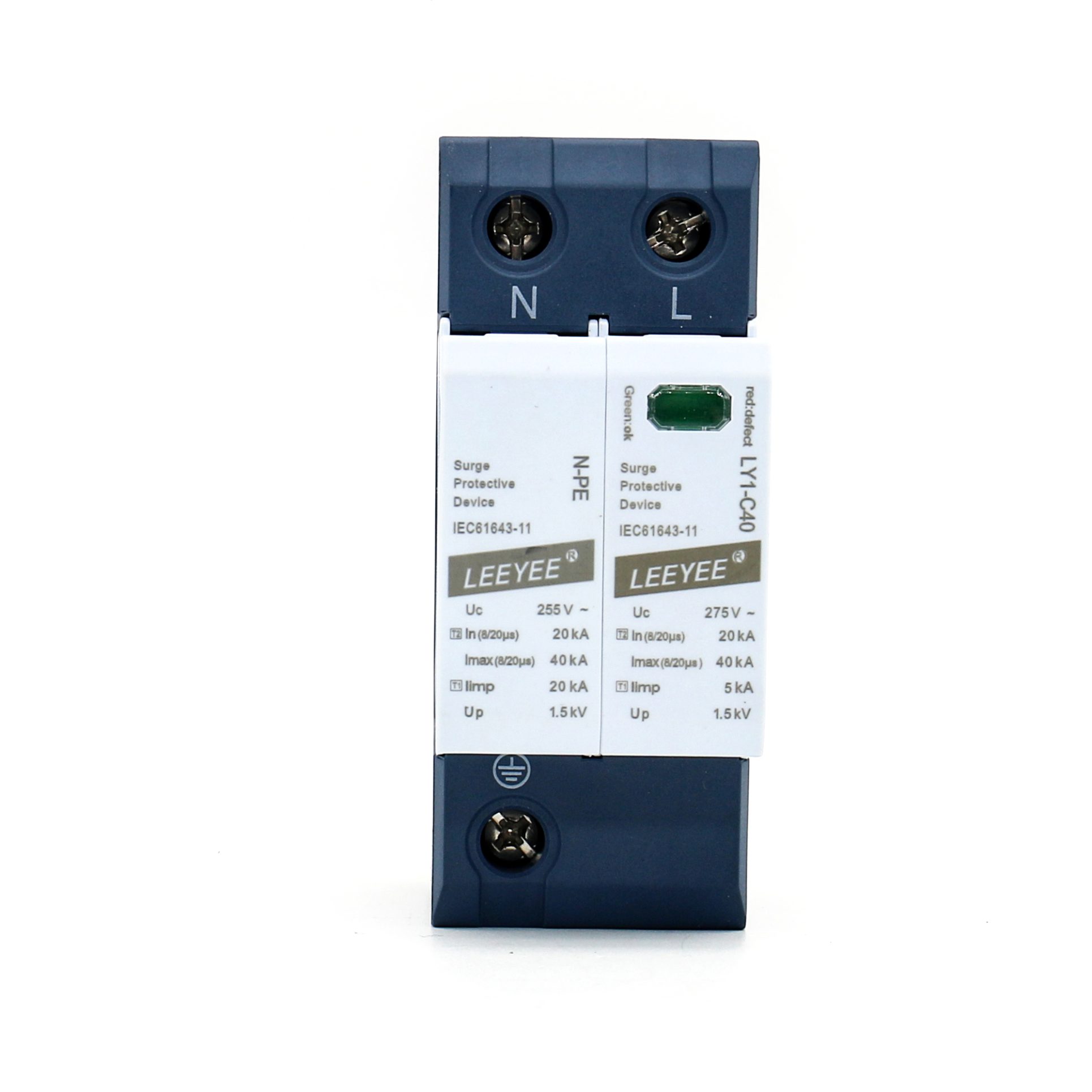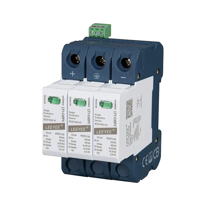
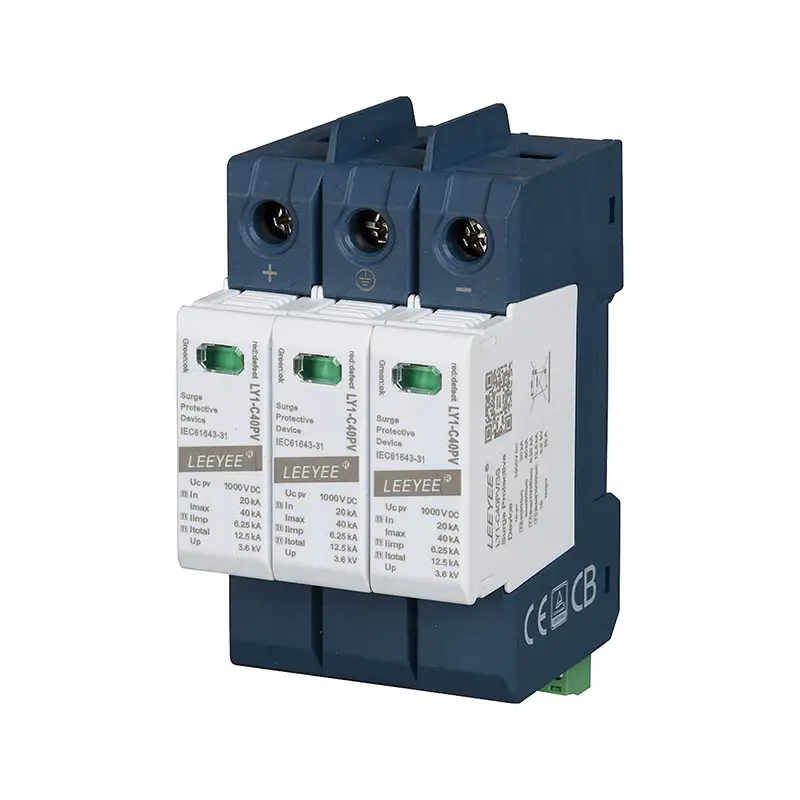
Technical Data
| Type | |
| SPD according to EN 61643-31 / IEC 61643-31 | type 1+2 / class I+II |
| Max. continuous operating DC voltage (DC+)-PE,(DC-)-PE ,(DC+)-(DC-) Ucpv | 1500 V DC |
| Nominal discharge current (8/20μs) In | 20 kA |
| Maximum discharge current (8/20μs) Imax | 40 kA |
| Maximum impulse current (8/20μs) Itotal | 40 kA |
| Maximum impulse current (10/350μs) Iimp | 6.25 kA |
| Maximum impulse current (10/350μs) Itotal | 12.5 kA |
| continuous current for PV application ICPV | 0.2 mA |
| Voltage protection level (DC+)-PE,(DC-)-PE (DC+)-(DC-) Up | 5.0 kV |
| Response time tA | 25 ns (L-N) |
| Short-Circuit Current Rating Iscpv | 2000 A |
| Residual current a.c. and d.c. IPE | 0.3 mA(DC), 0.3 mA(AC), |
| Humidity range | 5% … 95% |
| Range of operating temperatures TU | -40°C … +70°C |
| Atmospheric pressure and altitude | 80k Pa … 106k Pa, -500 m … 2000 m |
| Operating state / fault indication | Green ok / Red defect |
| Number of ports | One port |
| Cross-sectional area (max.) | 2 AWG (Solid, Stranded) / 4 AWG (Flexible) 35 mm2 (Solid, Stranded) / 25 mm2 (Flexible) |
| For mounting on | 35 mm DIN rail acc. to EN 60715 |
| Enclosure material | thermoplastic |
| Place of installation | indoor installation |
| Degree of protection | IP 20 |
| Capacity | 4 module(s), DIN 43880 |
| Approvals | – |
| Type of remote signalling contact | changeover contact |
| a.c. switching capacity | 250V / 0.5 A |
| d.c. switching capacity | 250V / 0.1 A; 125 V / 0.2 A; 75 V / 0.5 A |
| Cross-sectional area for remote signalling terminals | max. 1.5 mm2 solid / flexible |
| Remote signalling alarming mode | Normal: closed; failure: open-circuit |
| Acessibility | Inaccessible |
| Protection fuction | Overcurrent |
| PV earthing system | Earthed and Unearthed (both) |
| SPD failure mode (OCFM/SCFM) | OCFM |
Circuit Diagram

Installation, Usage And Maintenance
This product can only be installed and maintained by qualified professionals. The installation position cannot be touched by hands. Ensure that it is unpowered and check whether the SPD is all right before installation. If there’s damage or the display window is red, the SPD cannot be used any more; if the window is green, the SPD is normal.
The installation of SPD should be based on Fig. 3 IEC 60364-5-53. The cross-sectional area of ground wire should not be less than 4 mm2, and the length of total lead not more than 0.5m.
The minimum distance from any earthed conductive surface at which the SPD can be installed is 8mm.
Connection of remote signalling alarm: the SPD is provided with remote signalling interfaces (NC, COM and NO, normally closed), applicable for remote centralized monitoring or alarm.
After the connection, check if the module is fitted in. If so, NC and COM are closed; if not, repress the module.
Wiring Diagram