
Oil and gas facilities require surge protection strategies that match the complete electrical and instrumentation architecture. Long outdoor cables, remote field devices, control systems and communication networks can create multiple surge entry paths.
This guide helps EPC contractors, control panel builders, instrumentation engineers and industrial procurement teams evaluate surge protection for oil and gas applications, including upstream production facilities, midstream pipeline systems and downstream processing plants.
Quick Answer: Where Is Surge Protection Needed in Oil and Gas Systems?
| Application Area | Typical Equipment | Protection Consideration |
|---|---|---|
| Power distribution and local panels | Main panels, MCC panels, local control panels | Evaluate AC SPD according to system voltage, grounding arrangement and installation requirements. |
| Control and automation systems | PLC, DCS, SCADA, RTU cabinets | Consider both incoming power and connected interface protection. |
| Field instrumentation | Pressure, temperature, flow and level transmitters | Evaluate 4–20 mA, RTD, pulse and other signal protection requirements. |
| Communication networks | RS485, Modbus, Ethernet links | Confirm interface type, cable routing, shielding and grounding conditions. |
The correct surge protection solution depends on the actual project design. SPD selection should be confirmed according to equipment requirements, installation location and applicable project documents.
Table of Contents
Oil and Gas Surge Risks Across Upstream, Midstream and Downstream Operations
Oil and gas systems are distributed across large industrial areas, and surge exposure is not identical at every stage of operation. Outdoor instrumentation, remote stations and centralized control systems create different protection priorities.
| Operation Stage | Typical Equipment | Surge Risk Consideration |
|---|---|---|
| Upstream production | Well sites, remote instruments, RTU systems | Outdoor field cables and instrumentation exposed to lightning-related and switching transients. |
| Midstream transportation | Pipeline stations, compressor stations, monitoring systems | Long power, control and communication cable routes between separated locations. |
| Downstream processing | Refinery DCS, control cabinets, instrumentation networks | Protection of sensitive automation and measurement interfaces inside complex industrial systems. |
The protection approach should follow the actual power and signal paths instead of treating one cabinet or one field device as an isolated point.
Common Surge Entry Paths in Oil and Gas Facilities
Surge energy may enter through incoming power lines, outdoor instrument cables, communication lines or potential differences between separated grounding areas. For this reason, oil and gas surge protection should be reviewed as a system-level issue rather than a single-device choice.
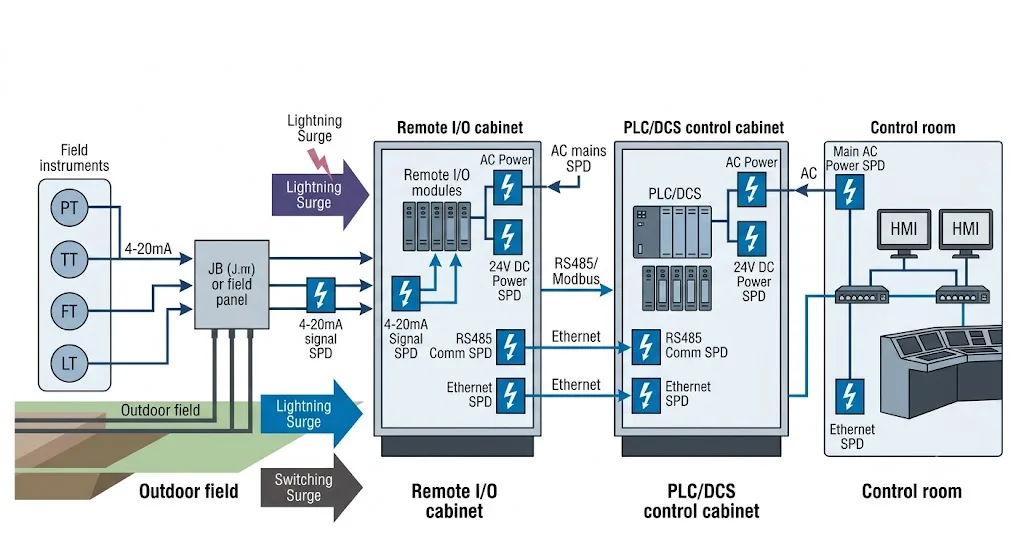
Oil and gas surge protection architecture showing common protection points from field instruments and remote interfaces to PLC and DCS systems.
A complete engineering review normally considers:
- Incoming AC power paths.
- 24 V DC control power circuits.
- Field instrument signal loops.
- Communication interfaces between field and control areas.
- Grounding, shielding and equipotential bonding.
Surge Protection for PLC, DCS and Control Panels
PLC and DCS systems are central to oil and gas automation. Transients entering through power or connected field wiring may disturb sensitive control electronics, communication modules and measurement interfaces.
For a control panel, the buyer should evaluate the complete cabinet architecture rather than selecting an SPD only by nominal voltage.
| System | Protection Review Point | What to Confirm |
|---|---|---|
| PLC / DCS cabinet | Incoming power and external interfaces | System voltage, grounding arrangement, cabinet layout and interface types. |
| Remote I/O cabinet | External field cable entry points | Signal type, cable routing, supply voltage and communication interface. |
| Instrument cabinet | Measurement and control circuits | Loop characteristics, wiring configuration and connected equipment requirements. |
Protecting Oil and Gas Field Instruments and 4–20 mA Loops
Pressure transmitters, temperature transmitters, flow meters and level instruments are often installed outdoors and connected to the control system through long field cables.
The correct signal protection device must match the real electrical interface. A 4–20 mA loop, RTD circuit, pulse input and RS485 line do not have the same operating characteristics, so they should not be treated as interchangeable applications.
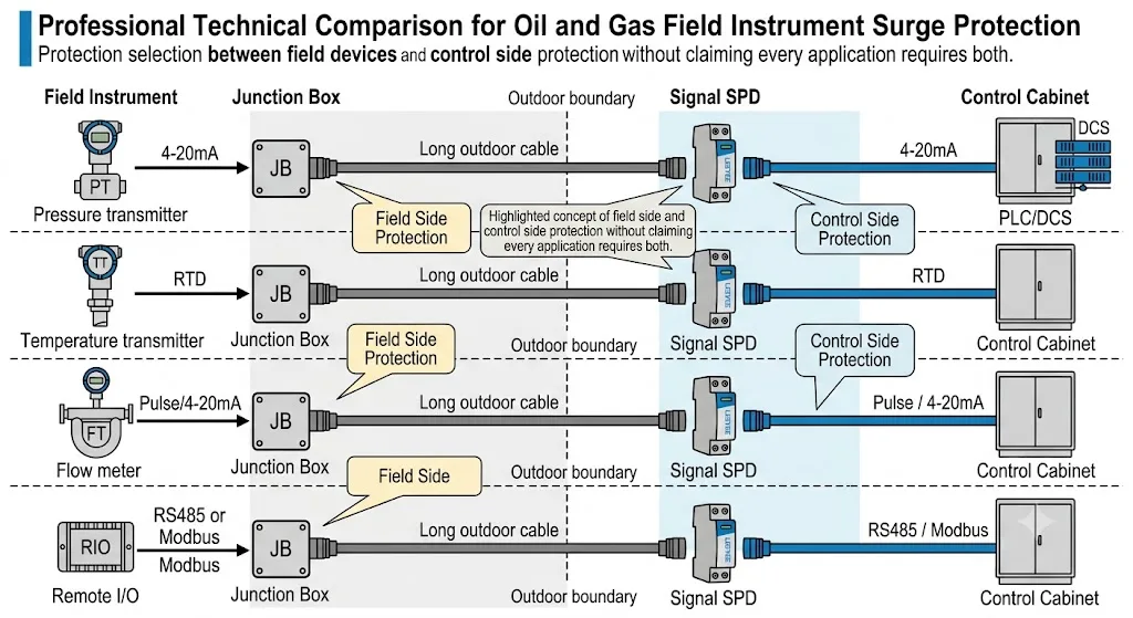
Comparison of surge protection considerations for common oil and gas field instruments and control interfaces.
For long field cable routes, engineers may evaluate protection at both ends of the circuit. This does not mean that every installation automatically requires two SPDs. The decision depends on the cable route, grounding design, equipment location and project risk assessment.
RS485, Modbus and Communication Interface Protection
Oil and gas facilities increasingly depend on digital communication for remote monitoring, control and diagnostics. RS485, Modbus and Ethernet links can provide another path for transient disturbances when cables run between separated equipment areas.
Before selecting communication surge protection, confirm:
- The communication protocol and electrical interface.
- The normal signal or operating voltage.
- The number of conductors and wiring configuration.
- The cable route and installation environment.
- The shielding and grounding method.
- Any system-manufacturer requirements for the interface.
Grounding, Shielding and Equipotential Bonding Matter as Much as the SPD
SPD performance depends on both the device and the installation. Connection length, protective earth path and bonding arrangement influence the residual voltage that reaches the protected equipment.
In industrial instrumentation systems, shielding and grounding also affect signal integrity. These details should therefore be reviewed together with the surge protection arrangement instead of being treated as separate topics.
Should Protection Be Installed at Both the Field Side and Control Room Side?
There is no universal answer. Dual-end protection can be considered when long cables connect equipment in separated locations, especially where lightning exposure or ground-potential differences are relevant.
However, the final decision should be based on the complete system design. The project engineer should confirm cable length, bonding, grounding, interface characteristics and the installation requirements of the connected equipment.
Hazardous Area and Explosion Protection Requirements
Oil and gas facilities may contain hazardous areas where specific explosion-protection requirements apply. Standard SPD certification does not automatically mean that the device is approved for direct installation in a hazardous area.
Before selecting an SPD for a hazardous location, confirm:
- Area classification and zone requirements.
- Explosion-protection concept used by the project.
- Intrinsic-safety requirements where applicable.
- Enclosure and installation requirements.
- Required ATEX, IECEx or other project-specific approvals where applicable.
- Control-system, instrument-manufacturer and EPC specifications.
If the SPD itself is not approved for installation in the classified area, the project may require another installation arrangement, such as placement within an approved enclosure or outside the hazardous zone. The correct method must be confirmed from the project documents and applicable standards.
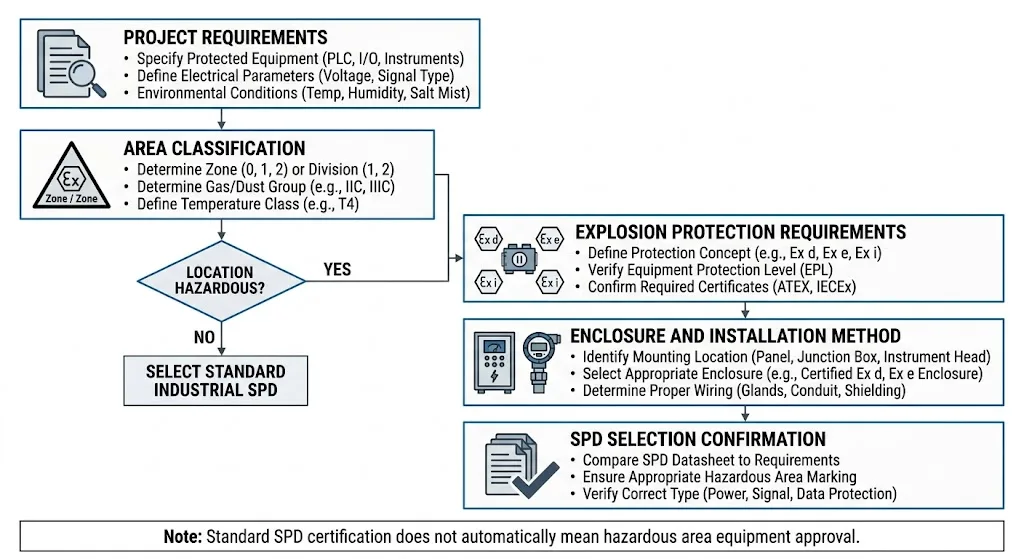
Hazardous area surge protection selection requires project-specific confirmation of classification, approvals, enclosure and installation method.
SPD Types Commonly Evaluated in Oil and Gas Systems
Oil and gas surge protection normally involves more than one SPD category. The exact combination depends on the system architecture.
| Application | Typical Protection Category | Main Confirmation Point |
|---|---|---|
| AC main or local panel | AC power SPD | System voltage, earthing arrangement, SPD type and installation position. |
| 24 V DC control circuit | DC power or control-circuit surge protection | Operating voltage, current and connected equipment. |
| 4–20 mA transmitter loop | Signal-line SPD | Loop voltage, wiring method, interface characteristics and grounding. |
| RS485 / Modbus | Communication-line SPD | Electrical interface, operating voltage, conductor arrangement and bandwidth requirements. |
The final SPD model must be selected from actual electrical parameters and project requirements. Application name alone is not enough to approve a device.
What Should an EPC Contractor or Panel Builder Verify Before SPD Approval?
Oil and gas projects normally involve multiple approval layers. A technically suitable device can still be rejected if its documentation, installation method or certification scope does not match the project requirement.
Before approval, procurement and engineering teams should review:
- Product datasheet and electrical parameters.
- Applicable test standard.
- Certificate scope and exact model coverage.
- Installation drawing and terminal arrangement.
- Grounding or bonding requirements.
- Hazardous-area restrictions where relevant.
- Panel or enclosure integration requirements.
- OEM label, packaging and documentation needs for repeat supply.
Before Ordering: Oil and Gas SPD Confirmation Checklist
- Application location: field instrument, junction box, local panel, control cabinet or control room.
- Upstream, midstream or downstream application.
- Hazardous or non-hazardous installation environment.
- Area classification and required approvals, if applicable.
- AC power, DC power, signal or communication protection requirement.
- System voltage and grounding arrangement.
- Signal type: 4–20 mA, RTD, pulse, RS485, Modbus, Ethernet or another interface.
- Number of conductors and wiring configuration.
- Cable route length and installation conditions.
- Required standards, certificates and project documents.
- Quantity, OEM label, packaging and documentation requirements.
Need Help Confirming an Oil and Gas SPD Configuration?
Share your system voltage, installation location, signal type and project requirements. LEEYEE can support technical parameter review for industrial control panels, field instrumentation and OEM requirements.
Request Model RecommendationFrequently Asked Questions
Field instruments connected through outdoor or long-distance cables may require surge protection evaluation because external wiring can introduce transient disturbances into sensitive measurement circuits. The requirement depends on the site risk and project design.
A signal-line SPD may be considered, but it must match the loop voltage, wiring arrangement and electrical characteristics of the transmitter circuit. The exact model should be confirmed from the instrument and control-system documentation.
Typical review points include incoming power, field cable entry points and communication interfaces. The final installation position depends on system architecture, grounding, cable routing and equipment requirements.
Not always. Dual-end protection may be considered for long or exposed cable routes, but the requirement should be confirmed from the system grounding, cable routing and project risk assessment.
Not automatically. Standard surge-protection certification does not by itself demonstrate hazardous-area approval. Area classification, explosion-protection method, enclosure and certificate requirements must be checked separately.
Typical documents include the product datasheet, applicable certificates, model-specific test information, installation instructions and drawings required by the project. Hazardous-area projects may require additional approval documents.
