
A fuse symbol in a circuit diagram identifies a fuse in the protected current path. The graphical form helps you locate the protective device, but the symbol alone does not tell you its current rating, voltage rating, breaking capacity, AC/DC suitability, or fuse category. This guide shows how to recognize the symbol, read common markings such as F1, and distinguish a fuse from other electrical protection symbols.
In IEC-style electrical diagrams, the general fuse function is represented by the IEC 60617-S00362 fuse symbol inserted in series with the conductor it protects. A reference such as F1 identifies that particular fuse on the drawing. The graphical symbol tells you that a fuse function is present; ratings and application details must be read from nearby annotations, the drawing legend, fuse schedule, BOM, or manufacturer documentation.
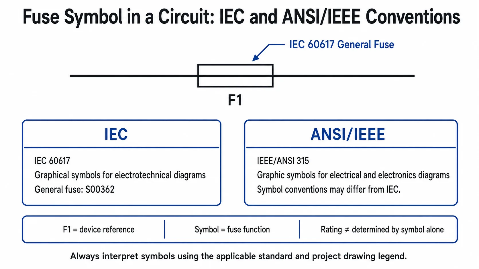
Table of Contents
What Does a Fuse Symbol Look Like in a Circuit?
The basic purpose of the symbol is simple: it marks the point in the schematic where a fuse is installed in the current path. Under IEC 60617, S00362 is the general fuse symbol. In a horizontal circuit the symbol is normally drawn in the conductor; in a vertical circuit the same graphical function may be oriented with the conductor direction.
This is different from showing a photograph of a glass fuse, NH fuse, cylindrical fuse, blade fuse, or PV fuse-link. A schematic symbol describes the electrical function in the drawing, not necessarily the physical construction of the installed product.
| Drawing element | What it normally communicates | What it does not prove by itself |
|---|---|---|
| Fuse symbol | A fuse function is present in that electrical path. | Current, voltage, breaking capacity, fuse class, physical size. |
| F1 | Reference designation used to identify the device on the drawing. | That the fuse is rated 1 A or belongs to a specific fuse type. |
| Rating annotation | Additional selected properties such as 32 A or 500 V AC. | All performance characteristics unless the drawing or datasheet states them. |
Fuse Symbol in an Actual Circuit Diagram
The easiest way to understand a fuse symbol is to stop looking at it in isolation. In a working schematic, the fuse normally appears in series with the conductor feeding the protected part of the circuit.
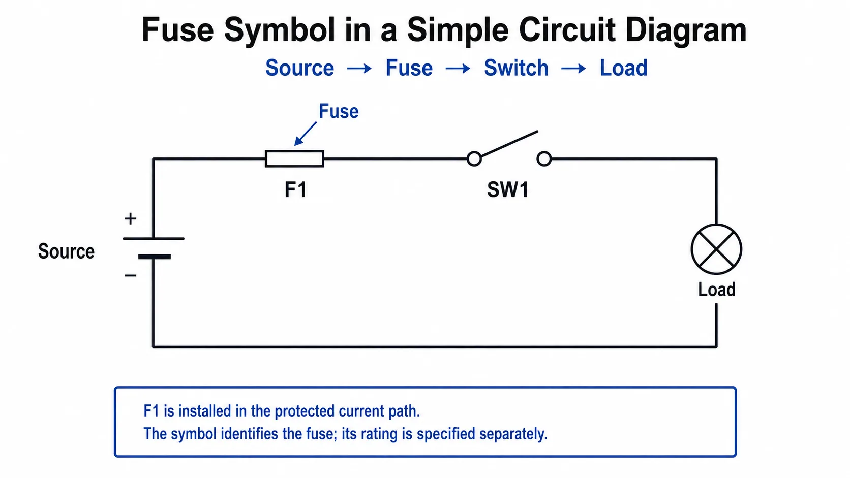
In this simplified example, the sequence is: Source → F1 fuse → SW1 switch → load → return. The exact physical location in a real system depends on the circuit design, but the drawing makes the fuse's electrical relationship to the protected branch clear.
Why the Fuse Appears in the Conductor
The protected circuit current passes through the fuse-link. When fault-current and time conditions cause the fuse element to operate, the current path is interrupted.
Why Position Matters
A schematic is not just a collection of symbols. Connectivity tells you which branch the fuse belongs to and which downstream devices are associated with that protection path.
Fuse Symbol in an Industrial Control Circuit
In control panels, a fuse may protect the control-voltage path feeding contactor coils, relays, controllers, transformers, or other control devices. The following example shows a simple series path from line to neutral.
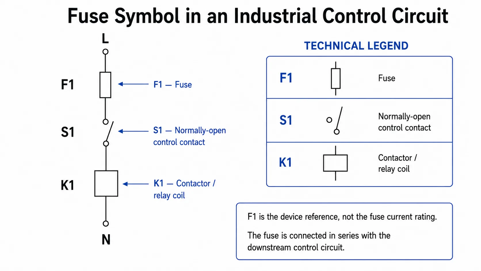
Here, F1 identifies the fuse, S1 identifies the control contact, and K1 identifies the contactor or relay coil. Their symbols have different functions even though all three appear in the same current path.
IEC vs ANSI/IEEE Fuse Symbols
Electrical drawings do not always use the same symbol library. IEC 60617 is the IEC database for graphical symbols used in electrotechnical diagrams. In North American and legacy engineering documentation, you may also encounter symbol conventions associated with ANSI/IEEE 315 or company-specific CAD libraries.
IEEE lists IEEE/ANSI 315-1975 as an inactive-reserved standard. Existing drawings may still use its conventions, so engineers reading older or project-specific documentation should not assume that every schematic follows the current IEC symbol set.
| Question | IEC-style drawing | ANSI/IEEE or project drawing |
|---|---|---|
| Symbol source | IEC 60617 graphical-symbol database. | May follow ANSI/IEEE references, legacy conventions, or project libraries. |
| Can the shape vary? | Use the applicable IEC symbol definition. | Yes, conventions may differ from IEC. |
| Does the symbol prove the rating? | No. | No. |
| Best interpretation source | Applicable IEC standard plus project legend. | Drawing legend, applicable standard, design documentation. |
How to Read F1, 32 A, gG and 500 V AC
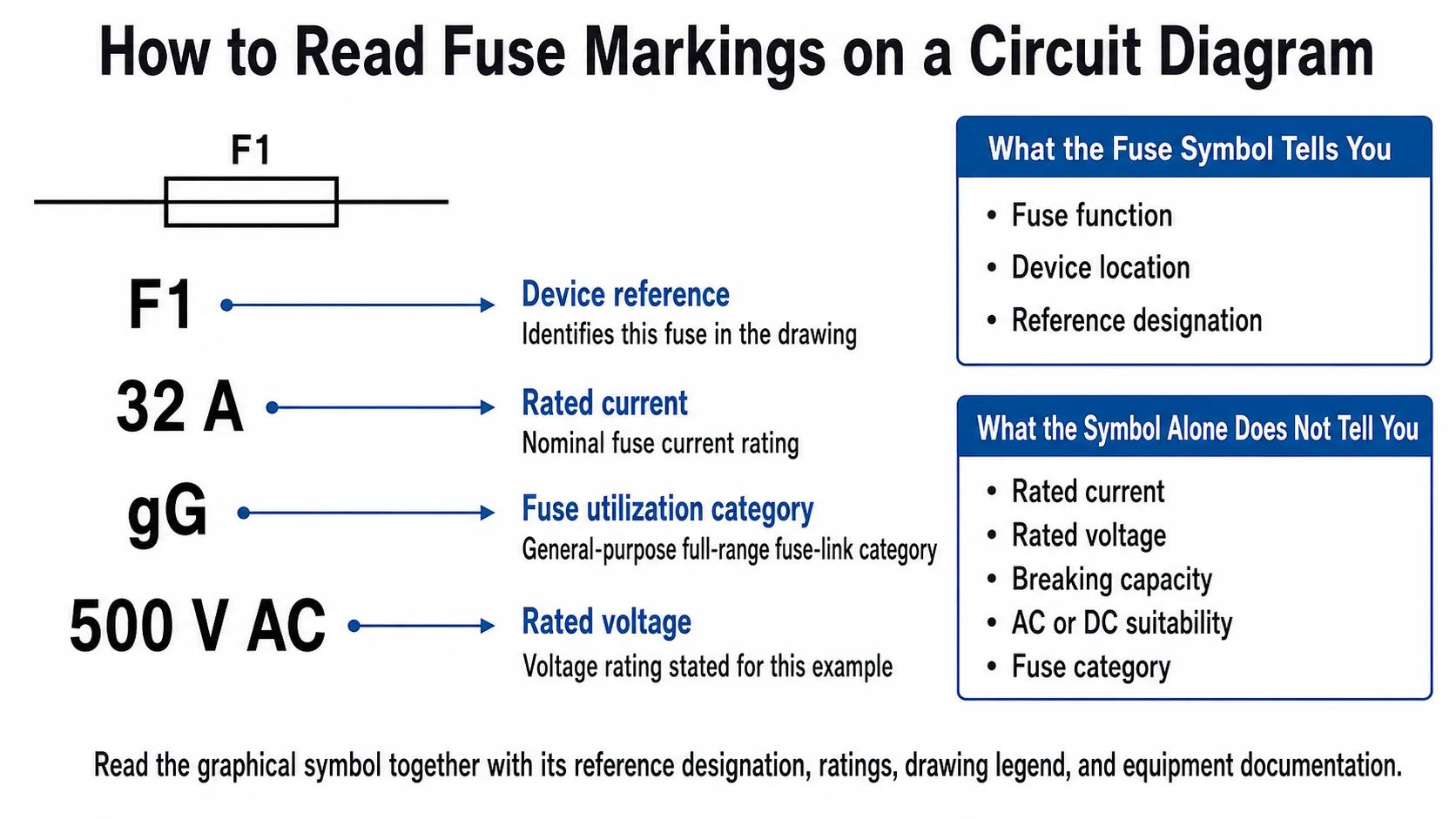
A schematic often becomes much more useful when the graphical symbol is combined with a reference designation and ratings. Consider the example:
F1 32 A gG 500 V AC
What a Fuse Symbol Can — and Cannot — Tell You
| Information | Can the generic symbol tell you? | Where to confirm it |
|---|---|---|
| Fuse function is present | Yes | Symbol and circuit connectivity. |
| Device location in the schematic | Yes | Circuit drawing. |
| Rated current | No | Annotation, BOM, schedule, datasheet. |
| Rated voltage | No | Annotation or datasheet. |
| Breaking capacity | No | Fuse datasheet and applicable standard. |
| AC or DC suitability | No | Circuit context, voltage designation, product documentation. |
| Fuse category | No | Marking, schedule, datasheet. |
| Physical format | No | BOM, part number or product documentation. |
This is why a schematic containing the correct symbol is not enough for procurement or replacement. A technician may know where the fuse belongs while still needing the exact part number, dimensions, voltage rating, current rating, utilization category, breaking capacity, and holder compatibility.
Fuse vs Fuse Holder vs Fuse-Switch: They Are Not the Same
Another common reading mistake is treating every fuse-related item as the same component. In practice, drawings can distinguish between a fuse-link, its holder, and fuse-combination devices that add switching or isolation functions.
| Device | Main role | Important interpretation point |
|---|---|---|
| Fuse-link | Performs the fuse protection function. | Normally replaced after operation. |
| Fuse holder | Holds and electrically connects the compatible fuse-link. | The holder itself should not be confused with the replaceable fuse-link. |
| Fuse-switch | Combines fuse protection with switching functionality. | Do not interpret it as a plain general fuse symbol. |
| Fuse-disconnector | Fuse combination incorporating disconnection/isolation functionality. | Isolation function matters when reading the device role in a distribution drawing. |
| Fuse switch-disconnector | Combines fuse, switching and disconnection functions. | Exact device requirements should be checked against the applicable standard and product documentation. |
IEC 60947-3 covers switches, disconnectors, switch-disconnectors and fuse-combination units used in low-voltage distribution and motor circuits. This is one reason a drawing may need more than the basic general fuse symbol when the device performs additional switching or isolation functions.
Looking for the physical device rather than the symbol?
See LEEYEE's fuse holder range, or review the broader What Is a Fuse? guide for fuse construction, applications and selection basics.
Does an AC Fuse and DC Fuse Use a Different Circuit Symbol?
Not necessarily. A generic fuse symbol by itself does not establish whether the installed fuse is approved for AC or DC service. The same general fuse function can appear in drawings for different systems, while the actual fuse construction and ratings required by those systems may be very different.
Look for System Context
Line/neutral designations, AC voltage labels, transformer relationships and the equipment schedule help establish the electrical system in which the fuse is used.
Look for Polarity and DC Ratings
Positive/negative conductors, DC bus labels, PV string notation, battery connections and explicit DC ratings are stronger evidence than the generic fuse symbol alone.
Fuse vs Circuit Breaker vs Resistor Symbols
These three devices can all appear in a conductor path, but their electrical purposes are fundamentally different. Confusing them can lead to an incorrect interpretation of the circuit.
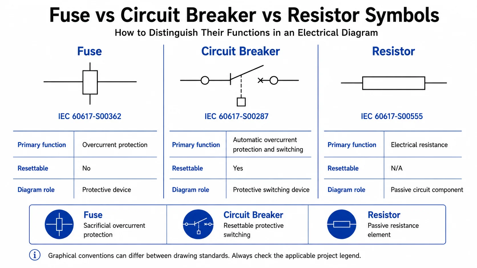
| Component | Primary function | Resettable? | IEC reference shown |
|---|---|---|---|
| Fuse | Overcurrent protection using a replaceable fuse-link. | No | IEC 60617-S00362 |
| Circuit breaker | Automatic protective switching, typically for overcurrent protection according to the device type. | Yes | IEC 60617-S00287 |
| Resistor | Provides electrical resistance as a passive circuit element. | N/A | IEC 60617-S00555 |
A circuit breaker should also not be confused with a surge protective device (SPD). A conventional fuse or circuit breaker is primarily an overcurrent-protection device, while an SPD is intended to limit transient overvoltage and divert surge current according to its design.
For protection coordination around SPDs, see How to Choose Fuses or MCB for SPD.
How Fuse Symbols Appear in Real Electrical Drawings
1. Industrial Control Panels
Control schematics often use fuse references such as F1, F2 or similar project designations on control-voltage branches. The drawing should be read together with terminal numbers, device references, coil references and the component schedule.
2. Distribution Boards
In distribution drawings, a fuse may appear upstream of a feeder, load, transformer or other branch equipment. If the assembly also provides switching or isolation, the drawing may use a more specific fuse-combination representation rather than a basic fuse symbol.
3. Solar PV and Combiner-Box Circuits
PV drawings make the distinction between series and parallel protective functions especially useful. A PV string fuse is installed in the relevant current path, while a DC surge protective device is normally connected as a surge-protection branch rather than being placed in series like a fuse.
For PV-specific protection context, see the Solar PV Surge Protection Guide and LEEYEE's PV fuse holder products.
Common Fuse Symbol Interpretation Mistakes
Frequently Asked Questions
What is the symbol for a fuse in a circuit?
In IEC-based drawings, IEC 60617-S00362 is the general fuse symbol. It is inserted in the conductor path to identify the fuse function. Other drawing systems can use different conventions, so the project legend should also be checked.
What does F1 mean on a circuit diagram?
F1 is commonly used as a device reference identifying a particular fuse on the drawing. It does not mean the fuse is rated 1 A and does not by itself specify the fuse type.
Is the IEC fuse symbol different from an ANSI or IEEE fuse symbol?
The graphical conventions can differ. IEC 60617 provides IEC electrotechnical symbols, while older or project-specific North American drawings may use ANSI/IEEE conventions or company symbol libraries. Always use the standard and legend applicable to the actual drawing.
Does a DC fuse have a different circuit symbol?
Not necessarily. The generic symbol alone may not establish whether the fuse is intended for AC or DC use. Confirm polarity, system voltage, annotations, fuse schedule and the product datasheet.
Is there a separate symbol for a slow-blow fuse?
Do not assume that every speed characteristic or physical fuse construction has a unique universal schematic symbol. Operating characteristics should be confirmed from markings, drawing notes, the BOM or manufacturer documentation.
What is the difference between a fuse symbol and a circuit breaker symbol?
They represent different protective devices. A fuse operates through a fuse-link that must normally be replaced after operation, while a circuit breaker is a resettable protective switching device. IEC 60617 therefore assigns them different graphical symbols.
Is a fuse holder the same as a fuse?
No. A fuse holder provides the mechanical and electrical connection for a compatible fuse-link. The fuse-link is the element that performs the fuse protection function.
Can a fuse symbol tell me the fuse rating?
No. Rated current, rated voltage, breaking capacity, utilization category and other selection data must be obtained from annotations, schedules, the BOM, product markings or the manufacturer's technical documentation.
Technical References
This guide separates standardized graphical-symbol references from project-specific drawing conventions. For engineering work, always confirm the edition and requirements applicable to the actual installation.
- IEC 60617-S00362 — Fuse, general symbol
- IEC 60617-S00287 — Circuit breaker
- IEC 60617-S00555 — Resistor, general symbol
- IEC 60269-1 — Low-voltage fuses, general requirements
- IEC 60947-3 — Switches, disconnectors, switch-disconnectors and fuse-combination units
- IEEE/ANSI 315-1975 — Graphic Symbols for Electrical and Electronics Diagrams
Need a Fuse or Circuit-Protection Product for Your Application?
For OEM, distribution or panel-building requirements, send LEEYEE your system voltage, rated current, fuse format, application and target market. Our team can help identify the relevant product range and supporting technical information.
Technical note: schematic interpretation does not replace circuit design, fuse coordination, short-circuit assessment, manufacturer instructions, or the standards applicable to a specific installation. Electrical design, selection and installation should be carried out by qualified personnel.
